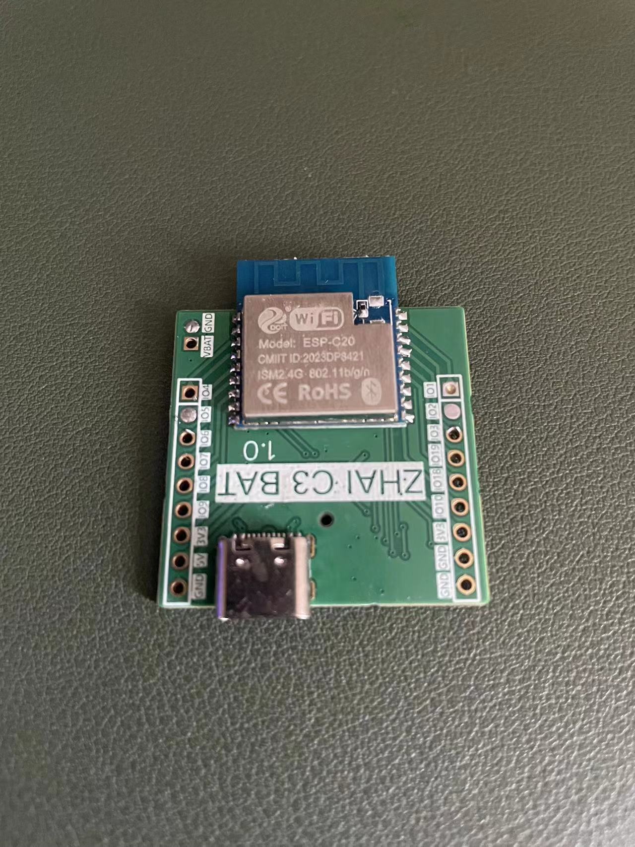
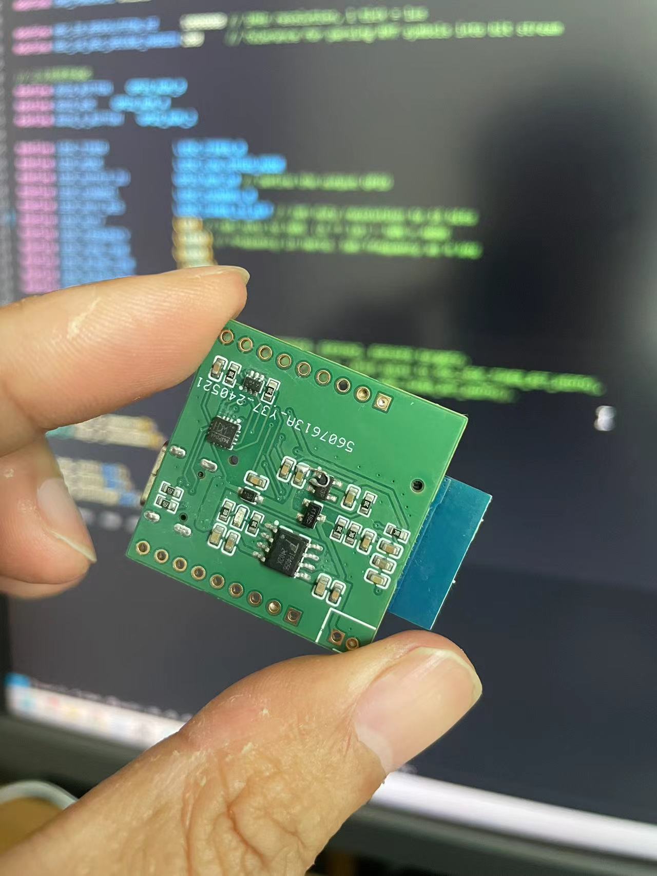
My recent projects have all been based on lithium battery charging, so I integrated the charging chip. Considering the limited pins on the ESP32C3, I introduced a serial port chip, reserving USB pins 18 and 19 for application use. The bug with the flying wire in the screenshot
regarding GPIO 0 voltage detection has been resolved.
This project utilizes the CH32V203C8T6 wireless remote control, which can be paired with the custom-designed LORA3A22 module from Zhufei to create a wirelessly controlled car. It can be used in the 19th National Intelligent Car Competition.
This project is a wireless remote control based on the CH32V203C8T6, which can be used with the customized LORA3A22 module from Zhufei to realize a wireless remote-controlled car. It can be used in the 19th Intelligent Car Competition.
Schematic diagram:

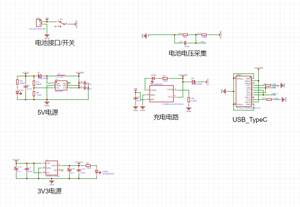

I. The remote control supports Type-C power supply or 1S lithium battery power supply, and has a built-in charging circuit, which can charge the 1S lithium battery via Type-C. It supports low battery voltage indication, LED indication of working status, etc.
II. It uses the TP4065 battery charging chip. The TP4065 is a complete lithium battery charger. It has the following advantages: 1. World's first single chip with reverse polarity protection for battery positive and negative terminals and reverse polarity protection for input power supply. 2. The maximum charging current can be set to 600mA, which is set to 500mA in this project. 3. It automatically performs trickle, constant current, and constant voltage control. 4. The SOT23-5 package and fewer external components make the TP4065 an ideal choice for portable applications.
III. The wireless module uses the customized LORA3A22 module from Zhufei Technology, which has the following advantages: 1. Supports sleep mode with a sleep current as low as 2.4uA. 2. High transmit power, up to 22dBm. 3. Maximum transmission distance up to 5km. 4. Wide baud rate range: 1200bps to 115200bps. 5. Eight-level adjustable airspeed: 1.2 to 62.5kbps. 6. Adjustable wireless frequency from 410 to 525MHz, with 116 channels.
PCB Design
: PCB size within 10*10.
Line Spacing: High-current lines are treated with large-area copper plating; power lines are 30mil, signal lines are 10mil.
Copper Silkscreen: Indicates power, download, peripheral interfaces, and serial port, and adds the project name and logo.

Circuit Debugging and
Soldering: Solder the switch and each power module first, testing after soldering one power module. This ensures that each module is problem-free, and makes troubleshooting easier when problems occur.
A charging station with a single DC input and a maximum output of 320W, supporting fast charging protocols such as PD100W/PD65W/QC/VOOC.
This small, high-power charging station is built using the Zhirong SW318S/SW3526 and Ingenic IP6505T chipsets. It features
1*PD 100W, 2*PD 65W, and 4*24W
outputs, with a maximum input voltage of 32V. Multiple ports offer independent output, supporting all charging protocols including PPS/PD3.0/PD2.0/QC4+/QC4/QC3.0/QC2.0/AFC/FCP/VOOC.
The station is compact, with a PCB size of 58*100mm and a thickness of approximately 23mm after casing. While
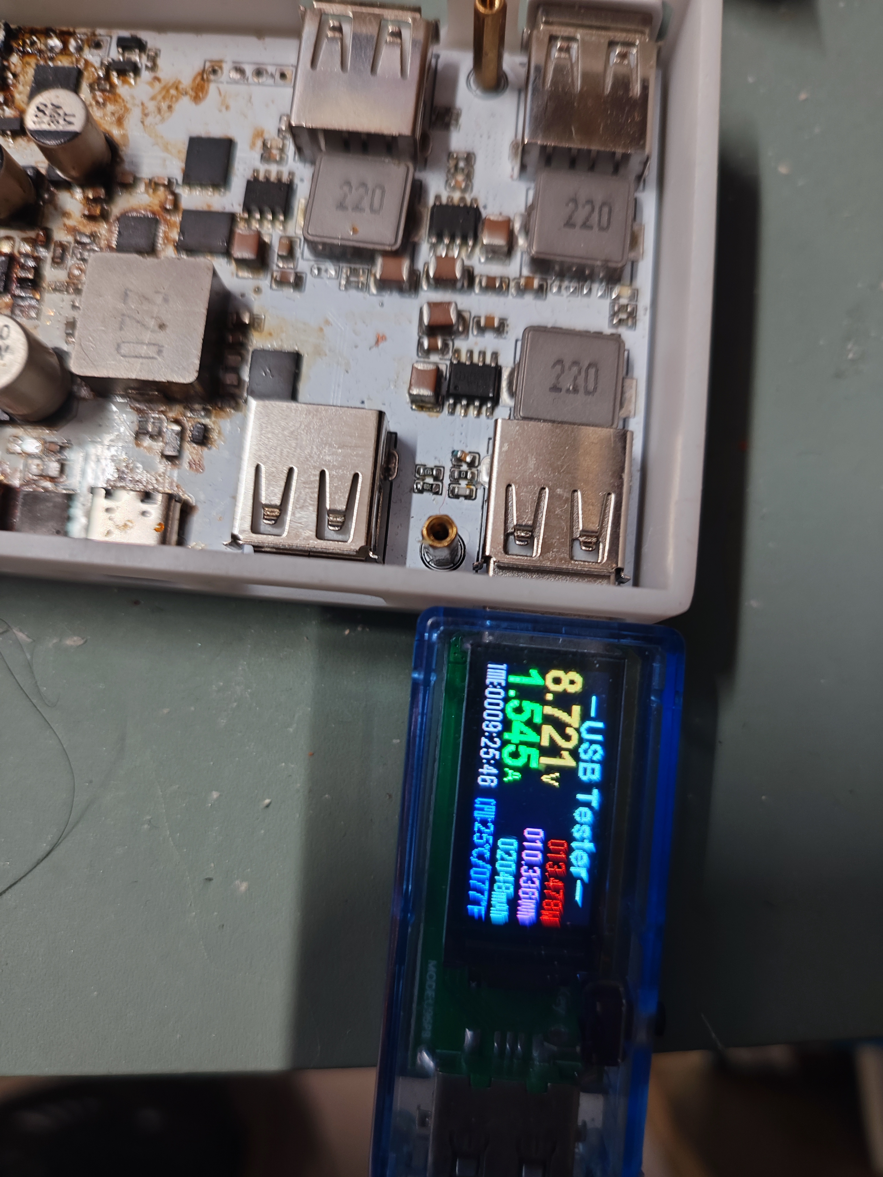
the author lacked a USB-C port current and voltage meter, tests with PD-compatible devices confirmed a normal 20V output.
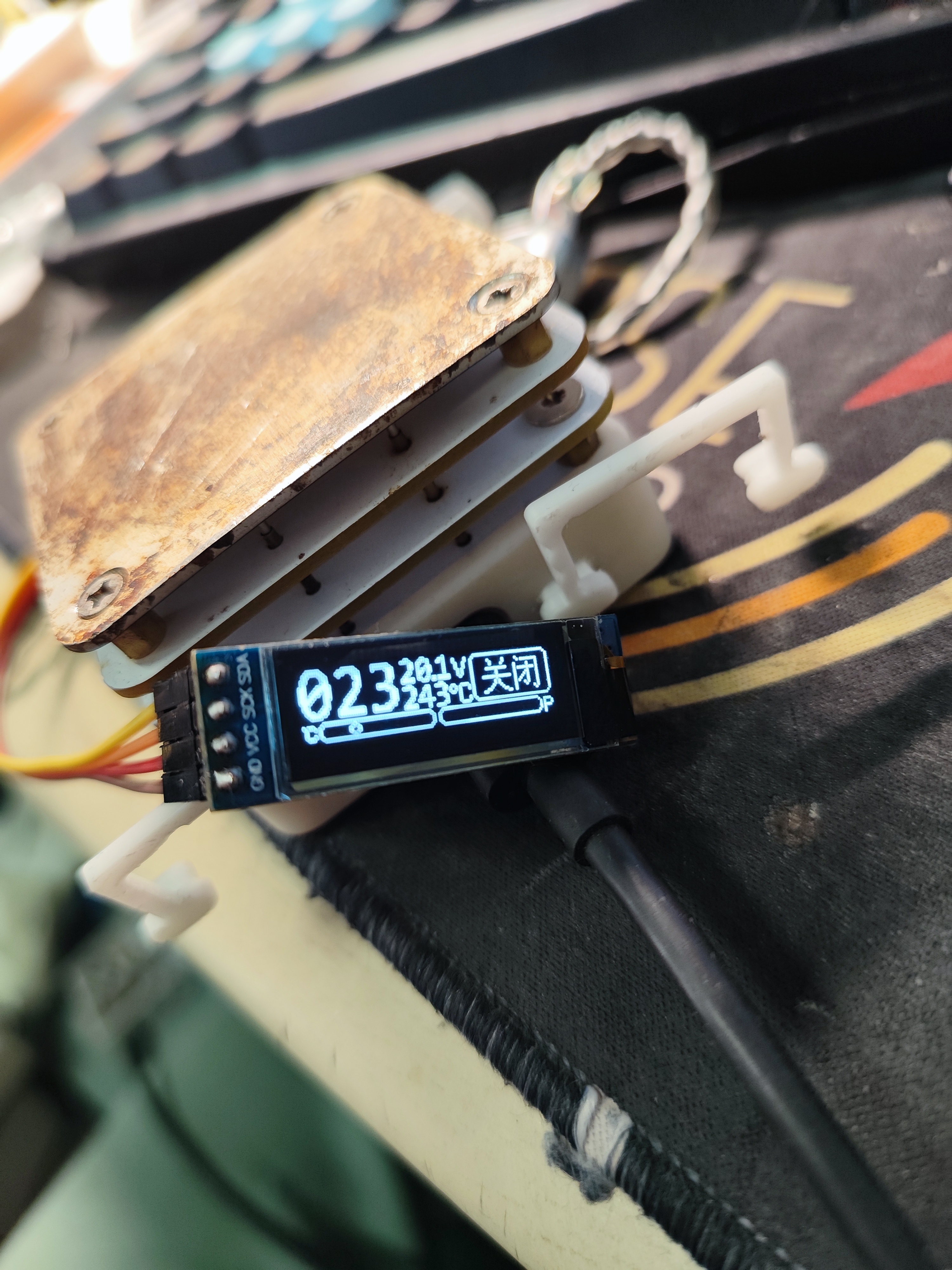
The onboard ESP32 provides voltage detection and digital display, with the three high-power channels supporting current and power display.
Casing files and the digital display program will be uploaded later.
The casing files and
power display program have been uploaded.
The casing uses a two-layer copper pillar connection,
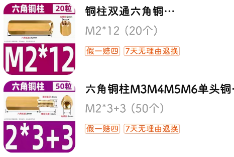
with an M2x3 module installed below and an M2x9 module above.
Under the outer shell. step
On the outer shell. step
The main controller is an ESP32C3 microcontroller with firmware named ESPHome. It outputs PWM signals to control the speed of the brushless motor on its built-in driver board, as well as an oscillating motor and temperature detection. Connecting to Home Assistant allows for smartphone control of the fan, timed deceleration, and prevents waking up from the cold at night.
[Modify a brushless fan for HA connection for only 40 yuan] https://www.bilibili.com/video/BV1gS411c7db/?share_source=copy_web&vd_source=8390ac6a62f861f9b2346582ab353abd
Module: esp32-c3-wroom-02-n4
Power supply: 12-24V is fine
The encoder button is the boot button. The surface-mount NTC resistor is easily affected by temperature, so it is best to use an NTC resistor with wires. It is not necessary to solder it. If you do not need physical speed control, you can also skip soldering the encoder. When burning, just short the S pin to ground to power on.
This replaces the original programming cable, sound card, and USB-to-serial adapter of the walkie-talkie. It uses a Type-C interface and an STM32 microcontroller to simulate the above functions.
This project briefly introduces
how a program written in an STM32 microcontroller enables a device to exhibit the same characteristics as the CM108 sound card, allowing control of the PTT (Push-to-Talk) via DireWorf software. It also features serial port control of the PTT and can be used with APRSDroid on mobile phones.
This project redesigned some circuitry using LCSC EDA, maintaining functional compatibility with the original. The original author, skuep,
has attached a GitHub page with a brief explanation of how to use it in the "How to use" section.
Additional notes:
Because many audio plugs use low-quality plastic that is not heat-resistant, the soldering points and audio contacts are often pressed together with plastic. Therefore, soldering audio plugs must be done quickly. If the soldering speed is too slow, the high temperature may cause the plastic to melt and deform, leading to poor contact or a short circuit. Poor contact may cause partial functional failure, while a short circuit may trigger transmission when the handheld radio is plugged in. Therefore, when soldering audio plugs, it is essential to operate quickly and minimize the soldering temperature.
If the audio plug does not readily accept solder, consider using "stainless steel flux." However, please note: Flux increases the contact area of the solder, which leads to a significant increase in heat transfer efficiency, making the plastic plug more susceptible to melting. Therefore, please use it with caution.
During transmission, the radio can easily interfere with USB communication. This interference manifests as an inability to stop transmission once PTT transmission is controlled via software. This is likely because electromagnetic waves interfere with USB communication, preventing the command to stop transmission from reaching the AIOC. Therefore, using a high-quality and as short as possible USB cable is essential.
The plug plastic is also soluble in board cleaning solution, so avoid contact with board cleaning solution after soldering the plug.
Use when both QR codes correspond to white and black silkscreen printing. White silkscreen printing is used by default.
AIOC
This is the Ham Radio All-in-one-Cable. It is currently in beta testing phase - Be wary! Please read this README carefully before ordering anything.
What does it do?
The AIOC is a small adapter with a USB-C connector that enumerates itself as a sound-card (eg for APRS purposes), a virtual tty ("COM Port") for programming and asserting the PTT (Push-To-Talk) as well as a CM108 compatible HID endpoint for CM108-style PTT (new in firmware version 1.2.0).
You can watch the videos of the Temporarily Offline and HAM RADIO DUDE YouTube channels below.
Features
Cheap & Hackable Digital mode USB interface (similar to digirig, mobilinkd, etc...)
Programming Cable Function via virtual Serial Port
Compact form-factor (DIY overmolded enclosure is currently TBD)
Based on easy-to-hack STM32F302 with internal ADC/DAC (Programmable via USB bootloader using DFU)
Can support Dual-PTT HTs
Compatibility
Software
Direwolf as AX.25 modem/APRS en+decoder/...
APRSdroid as APRS en+decoder
CHIRP for programming
... and more
Tested Radios (so far)
Wouxun UV-9D Mate (CHIRP + APRS)
Baofeng UV-5R (CHIRP + APRS)
BTECH 6X2 (CHIRP)
Future Work
Overmolded enclosure design (DIY using 3D-Printed mold and Resin/Hotglue)
Maybe integrate a TNC Modem with KISS interface? (I am not sure if that is worth the effort)
"High-Performance" VOX emulation with advanced features (eg pre-triggered VOX to activate PTT a few milliseconds before data, reduced tail time)

How To Fab
Go to JLCPCB.com and upload the GERBER-k1-aioc.zip package (under kicad/k1-aioc/jlcpcb)
Select PCB Thickness 1.2mm (that is what I recommend with the TRS connectors I used)
You may want to select LeadFree HASL
Select Silkscreen/Soldermask color to your liking
Check "PCB Assembly"
PCBA Type "Economic"
Assembly Side "Top Side"
Tooling Holes "Added by Customer"
Press Confirm
Click "Add BOM File" and upload BOM-k1-aioc.csv
Click "Add CPL File" and upload CPL-k1-aioc.csv
Press Next
Look Through components, see if something is missing or problematic and press Next
Check everything looks roughly good (rotations are already baked-in and should be correct). Save to Cart
This gives you 5 (or more) SMD assembled AIOC. The only thing left to do is soldering on the TRS connectors (see here).
The total bill should be around 60$ US for 5 pieces plus tax and shipping from China.
How To Assemble
This is the process I use for building. See photographs in images folder.
You need to use Monacor PG-204P and PG-203P or compatible TRS connectors (2 solder lugs and a big tab for the sleeve connection)
Cut the 2.5mm and 3.5mm TRS sleeve tab where the hole is located
Put both TRS connectors into the 3d-printed solder guide (or a cheap HT that you don't mind potentially damaging). Make sure, that they are seated all the way in. If the holes in the solder guide are too small, you can ream them using a 2.5mm and 3.5mm drill bit.
Insert the AIOC PCB into the solder guide
Solder sleeve tab on the back side for both TRS connectors first
Turn around PCB and solder remaining solder lugs
How To Build
For building the firmware, clone the repository and initialize the submodules. Create an empty workspace with the STM32CubeIDE and import the project.
git clone
git submodule update --init
Start STM32CubeIDE and create a new workspace under /stm32
Choose File->Import and import the aioc-fw project in the same folder without copying
Select Project->Build All and the project should build. Use the Release build unless you specifically want to debug an issue
How To Program
Initial programming
The following steps are required for initial programming of the AIOC:
Short outermost pins on the programming header. This will set the device into bootloader mode in the next step.
Connect USB-C cable to the AIOC PCB
Use a tool like dfu-util to program the firmware binary from the GitHub Releases page like this:dfu-util -a 0 -s 0x08000000 -D aioc-fw-x-y-z.bin
Note that a libusb driver is required for this. On Windows there are additional steps required as shown here (DFuSe Utility and dfu-util). On other operating systems (e.g. Linux, MacOS), this just works ™ (provided libusb is installed on your system).
Remove short from first step, unplug and replug the device, it should now enumerate as the AIOC device
Firmware updating
Once the AIOC has firmware loaded onto it, it can be re-programmed without the above BOOT sequence by following these steps.
Note This requires firmware version >= 1.2.0. For older firmwares, the initial programming sequence above is required for updating the firmware.
Run dfu-util like thisdfu-util -d 1209:7388 -a 0 -s 0x08000000:leave -D aioc-fw-x-y-z.bin
This will reboot the AIOC into the bootloader automatically and perform the programming.
After that, it automatically reboots the AIOC into the newly programmed firmware.
Note Should you find yourself with a bricked AIOC, use the initial programming sequence above
How To Use
The serial interface of the AIOC enumerates as a regular COM (Windows) or ttyACM port (Linux) and can be used as such for programming the radio as well as PTT (Asserted on DTR=1 and RTS=0).
Note before firmware version 1.2.0, PTT was asserted by DTR=1 (ignoring RTS) which caused problems with certain radios when using the serial port for programming the radio e.g. using CHIRP.
The soundcard interface of the AIOC gives access to the audio data channels. It has one mono microphone channel and one mono speaker channel and currently supports the following baudrates:
48000 Hz (preferred)
32000 Hz
24000 Hz
22050 Hz (specifically for APRSdroid, has approx. 90 ppm of frequency error)
16000 Hz
12000 Hz
11025 Hz (has approx. 90 ppm of frequency error)
8000 Hz
Since firmware version 1.2.0, a CM108 style PTT interface is available for public testing. This interface works in parallel to the COM-port PTT.
Direwolf on Linux is confirmed working, please report any issues. Note that currently, Direwolf reports some warnings when using the CM108 PTT interface on the AIOC.
While they are annoying, they are safe to ignore and require changes in the upstream direwolf sourcecode. See https://github.com/wb2osz/direwolf/issues/448 for more details.
Notes on Direwolf
Follow the regular setup guide with direwolf to determine the correct audio device to use.
For the serial and CM108 PTT interfaces on Linux, you need to set correct permissions on the ttyACM/hidraw devices. Consult Direwolf manual.
Configure the device as follows[...]
ADEVICE plughw:,0 # <- Linux
ADEVICE x 0 # <- Windows
ARATE 48000
[...]
PTT CM108 # <- Use the new CM108 compatible style PTT interface
PTT DTR -RTS # <- Alternatively use an old school serial device for PTT
[...]
Notes on APRSdroid
APRSdroid support has been added by AIOC by implementing support for the fixed 22050 Hz sample rate that APRSdroid requires.
It is important to notice, that the exact sample rate can not be achieved by the hardware, due to the 8 MHz crystal.
The actual sample rate used is 22052 Hz (which represents around 90 ppm of error). From my testing this does not seem to be a problem for APRS at all.
However, since APRSdroid does not have any PTT control, sending data is currently not possible using the AIOC except using the radio VOX function. See https://github.com/ge0rg/aprsdroid/issues/324.
My previous experience is, that the Android kernel brings support for ttyACM devices (which is perfect for the AIOC) so implementing this feature for APRSdroid should theoretically be no problem.
Ideas such as implementing a digital-modes-spefic VOX-emulation to workaround this problem and let the AIOC activate the PTT automatically are currently being considered.
Voice your opinion and ideas in the GitHub issues if this seems interesting to you.
Notes on CHIRP
CHIRP is a very popuplar open-source programming software that supports a very wide array of HT radios. You can use CHIRP just as you would like with a regular programming cable.
Download:
Start CHIRP
Select Radio->Download from Radio
Select the AIOC COM/ttyACM port and start
Upload:
Select Radio->Upload to Radio
That's it
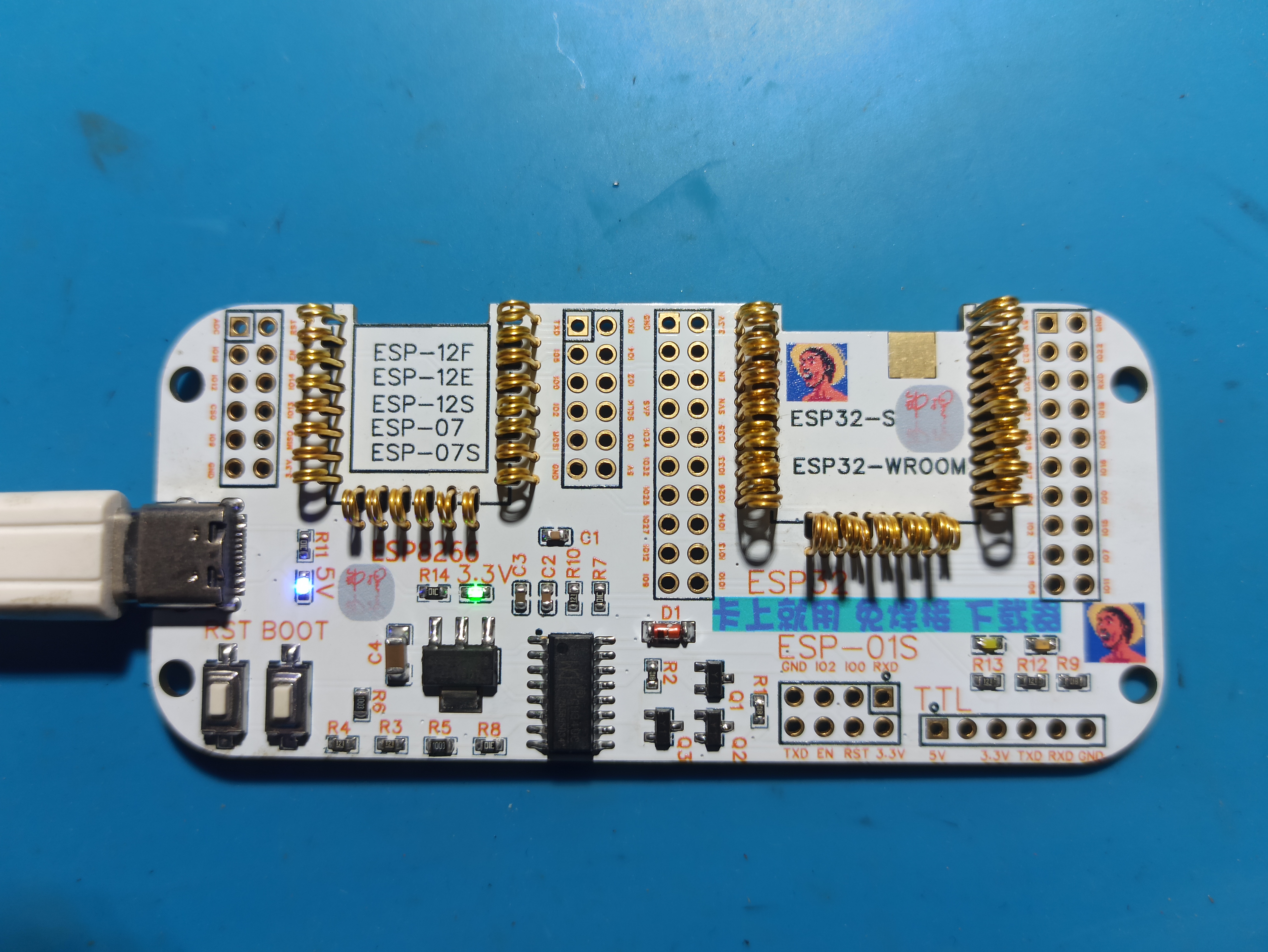
It saves a little money on the development board; it's ready to use right out of the box, making it very user-friendly for program burning and testing.

The antenna PCB has been removed for easier disassembly without affecting the signal.
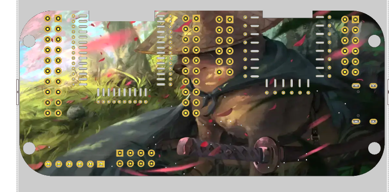
The following colored PCB images are from the second version. If you don't want to prototype the colored PCB, just delete the images and icons in the project.
The file path for the programming dock is available on Taobao.xlsx
PDF_Color silkscreened ESP12 and ESP32 quick downloader, burner, and burner rack.zip
Altium_Color Silkscreen ESP12 & ESP32 Quick Downloader/Burner/Burner Holder.zip
PADS_Color Silkscreen ESP12 & ESP32 Quick Downloader/Burner/Burner Holder.zip
BOM_Color silkscreened ESP12 and ESP32 quick downloader, burner, and burner rack.xlsx
94510
Mini_DisplayLED
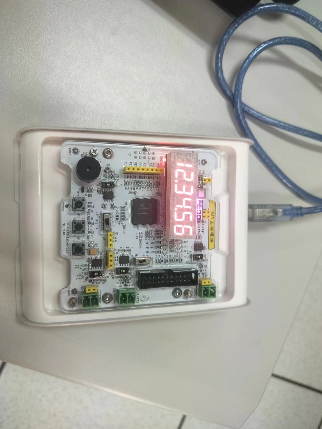
A 6-digit LED display module designed based on the sensor interface of the Newland M3 development board.
It has three status interfaces, one data interface, and is powered by a 5V power supply. There is slight leakage current after power is off.
Driver section:
The first 8 bits of input data control the segment selection of the digital tube, and the next 8 bits control the digit selection.
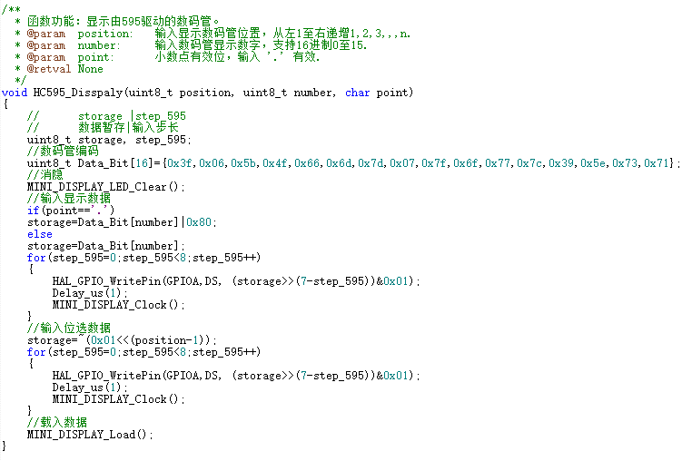
Example usage:
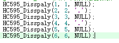
Actual display:
The leftmost digit is the first digit.
PDF_Mini_DisplayLED.zip
Altium_Mini_DisplayLED.zip
PADS_Mini_DisplayLED.zip
BOM_Mini_DisplayLED.xlsx
94511
Wireless charging IP6808 compatible with Apple devices - detailed specifications
Based on a circuit designed by an expert, I made some modifications.
It uses an IP6808 as the main controller, requiring minimal external circuitry. The maximum power is 15W.
I made some changes, including adding a few extra wires, for improved stability. For details
on printing custom icons on the JLCPCB panel,
please see the demo video.
Based on a circuit designed by an expert, I made some modifications. It uses an IP6808 as the main controller, requiring minimal external circuitry. The maximum power is 15W. I modified some components, added a few extra wires, and improved stability. For details on the custom icon printing on the JLCPCB panel, please see the demo video:
[DIY Wireless Charger by a Vocational School Student, Compatible with Apple and Android. The project is open-sourced on the LCPCB open-source hardware platform OSHWHub #Summer Electronics Fun Contest] https://www.bilibili.com/video/BV1ss421G71L/?share_source=copy_web&vd_source=7c5e51eac946cef7a4d7596a64cf9b21
bd384b73e88268185216cadcd17e9ea5.mp4
PDF_Wireless Charging IP6808 Apple Compatible - Very Detailed.zip
Altium Wireless Charging IP6808 Apple Compatible - Detailed Guide (zip)
PADS Wireless Charging IP6808 Apple Compatible - Detailed Guide (zip)
BOM_Wireless Charging IP6808 Compatible with Apple - Very Detailed.xlsx
94512
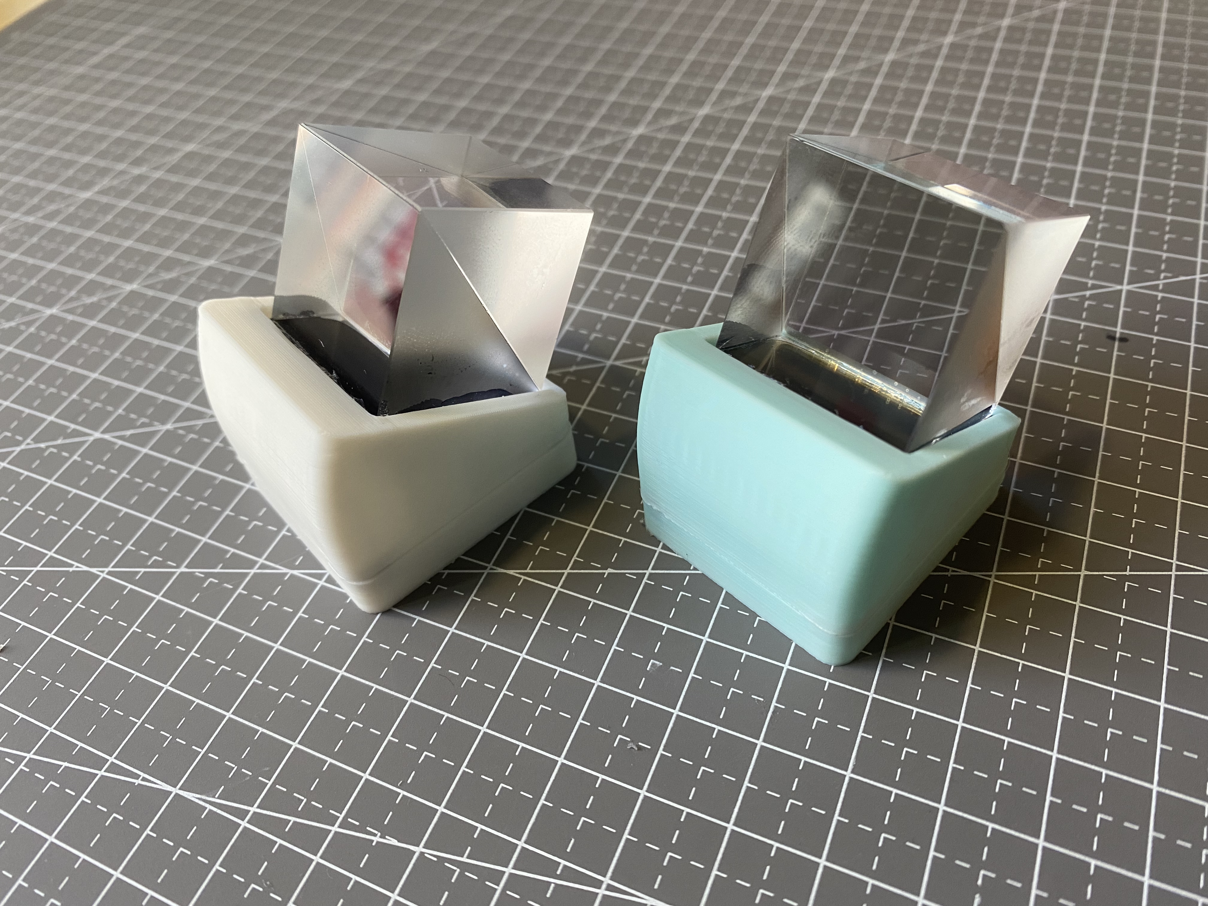
HoloCubic Reissue [with Complete Sharing Tutorial]
Replicating the Holocubic project
The problem requires
replicating Holocubic. The project mainly consists of two boards (main board and screen board). There are two versions of the main board, v1 and v2, both with modifications compared to the original. Version v2 is the closest to the original. For easier PCB routing, only the package of the main control chip was modified. Version v1 (four-layer board): Added a battery module and a power switch. Version v2 (two-layer board, recommended): Modified the ESP32-PICO-D4 package. Software instructions, 3D shell files, etc., have been uploaded. Software open-source address: https://github.com/wan-h/holocubic_reproduce. Reproduction tutorial : **Zhihu section**: [Holocubic Reproduction Journey - Preface](https://zhuanlan.zhihu.com/p/667687467) [Holocubic Reproduction Journey - Principles](https://zhuanlan.zhihu.com/p/668107235) [Holocubic Replica Journey - Hardware - Circuit Schematic](https://zhuanlan.zhihu.com/p/668943131) [Holocubic Replica Journey - Hardware - PCB Design](https://zhuanlan.zhihu.com/p/669356547) [Holocubic Replica Journey - Hardware - PCB Soldering](https://zhuanlan.zhihu.com/p/669744283) [Holocubic Replica Journey - Software - Project Architecture](https://zhuanlan.zhihu.com/p/670184699) [Holocubic Replica Journey - Software - Driver Porting](https://zhuanlan.zhihu.com/p/670385330) [Holocubic Replica Journey - Software - App Development](https://zhuanlan.zhihu.com/p/670804613) [Holocubic Replica Journey - Shell Part - 3D Printing](https://zhuanlan.zhihu.com/p/671441116) [Holocubic Replica Journey - Assembly Completed](https://zhuanlan.zhihu.com/p/672671669) **WeChat Official Account Sections**: [Holocubic Replica Journey - Preface](https://mp.weixin.qq.com/s/g9OoGMnk5hJdyEyZY1zoVg) [Holocubic Replica Journey - Principle Part](https://mp.weixin.qq.com/s/hCcCmEE-HVDEflkmTs4eXQ) [Holocubic Replica Journey - Hardware Part - Circuit Schematic](https://mp.weixin.qq.com/s/9BZ2hZZiAkcib54U-MHgQA) [Holocubic Replica Journey - Hardware - PCB Design](https://mp.weixin.qq.com/s/UG-cqXRy1sHwRkdve2HKiw) [Holocubic Replica Journey - Hardware - PCB Soldering](https://mp.weixin.qq.com/s/iGqCdDKC1GpauwrAINV9UA) [Holocubic Replica Journey - Software - Engineering Architecture](https://mp.weixin.qq.com/s/_jIpUm0_Vr3VP4WGBFgyiw) [Holocubic Replica Journey - Software - Driver Porting](https://mp.weixin.qq.com/s/LPaq20nl86-nybf8BDHKPg) [Holocubic Replica Journey - Software - App Development](https://mp.weixin.qq.com/s/clkCv0ckISnppMRNjqzFOA) [Holocubic Reissue Journey - Shell - 3D Printing](https://mp.weixin.qq.com/s/eF_fNTJvMFr8hR-gaSXPrQ) [Holocubic Reissue Journey - Assembly Complete](https://mp.weixin.qq.com/s/OH6-Obgg1hRzLUqWNXFC6w) Demo Video (Bilibili): https://www.bilibili.com/video/BV1hN4y1h719/?share_source=copy_web&vd_source=aa112a1eb5d3efeaf1237b8099bfc146 Physical Product Display and Description

PDF_HoloCubic Reissue [with Complete Sharing Tutorial].zip
Altium_HoloCubic Re-forged [with Complete Sharing Tutorial].zip
PADS_HoloCubic Reissue [with Complete Sharing Tutorial].zip
BOM_HoloCubic Reissue [with Complete Sharing Tutorial].xlsx
94513
electronic


 京公网安备 11010802033920号

 TN2-L2-H-4V


