This is an open-source Raspberry Pi pico oscilloscope from overseas, also available on the forum (https://oshwhub.com/ZEROREZ/fscope-250k5). The author has updated it, so I'm sharing it here.
The PCB resistor packages have been modified; I changed the 0603 to the 0805 I had on hand.
It requires the Scoppy Oscilloscope software to function. Advanced dual-channel functionality requires purchase; I bought mine for HKD 15 on the Google Play Store.
3D casing: https://www.printables.com/model/419547-oscilloscope-fscope-500k-dso-500k
Original open-source link: https://oshwlab.com/fruitloop57/fscope-250k5-v2_copy_copy_copy_copy
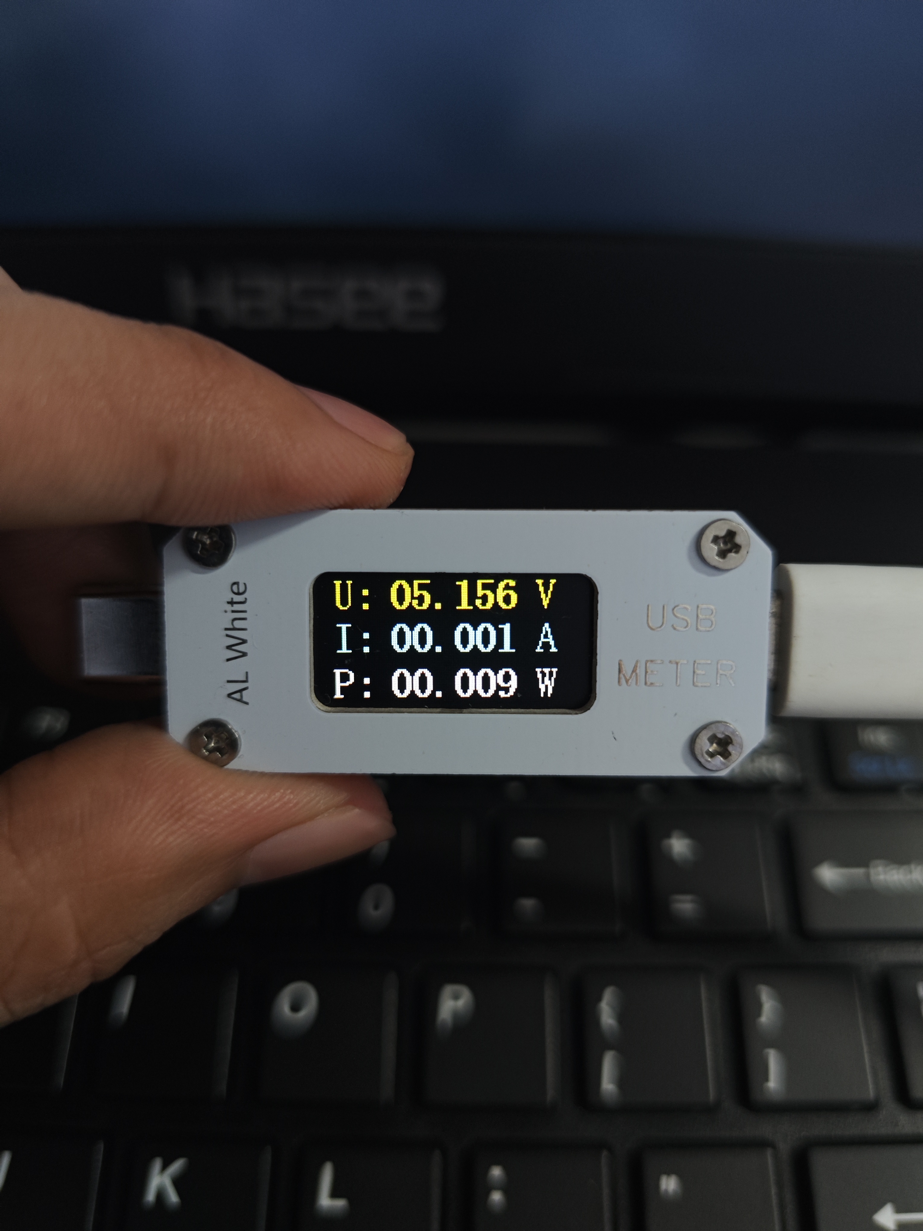
Based on the original simple ammeter design by a senior developer, and using the Air001 and 0805 resistors and capacitors on hand, I modified the layout, developed it using Keil 5, and made some changes to the interface display, adding a simple current curve display and screen backlight settings. This makes it more feature-rich than the original.
Original open-source link: https://oshwhub.com/wffg/type-c-dian-ya-dian-liu-biao
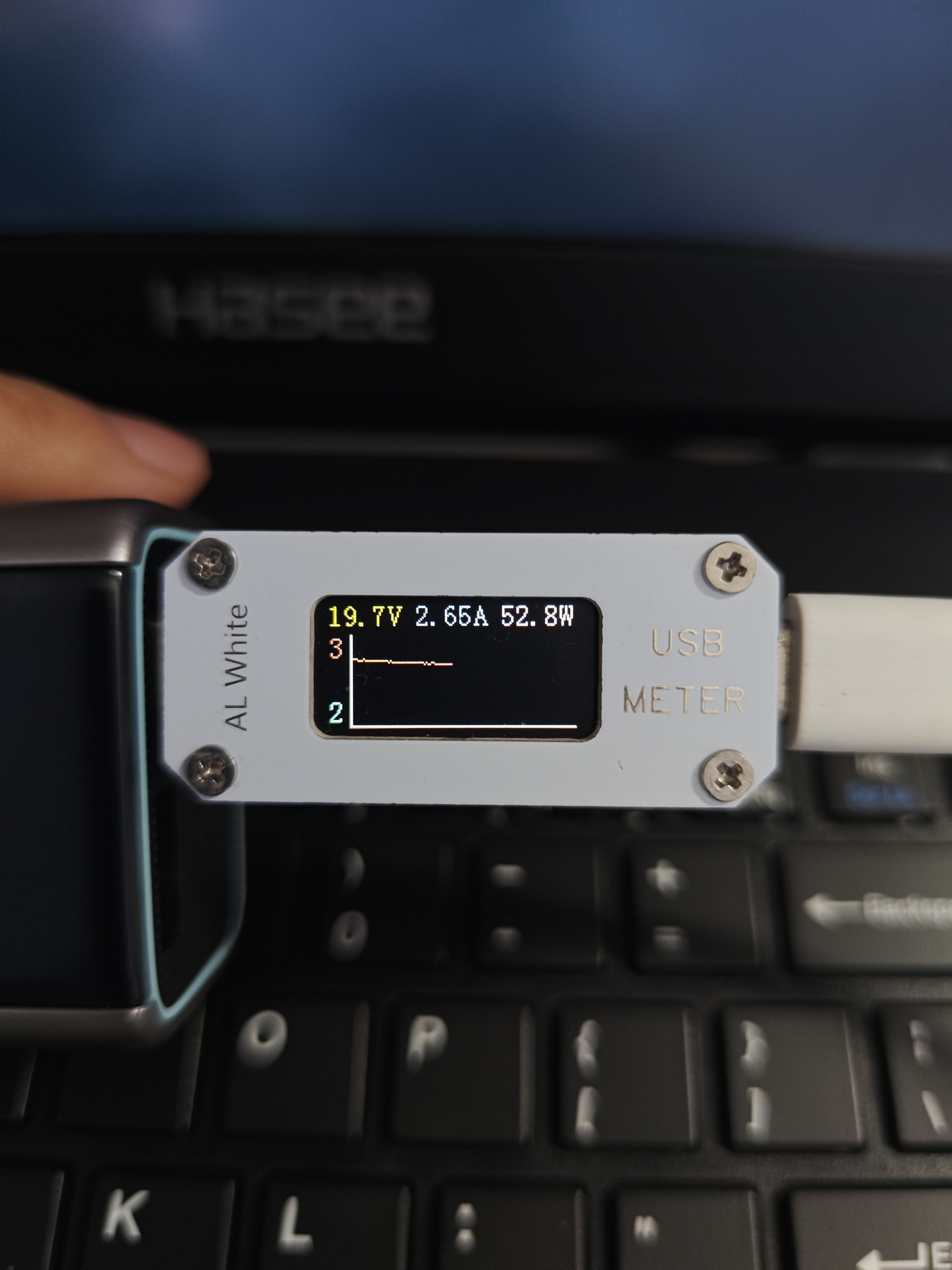
The Air001 used here doesn't have an external crystal oscillator; it uses an internal one, which normally has a maximum clock frequency of only 24MHz. The screen refresh rate is relatively slow, so for some fixed elements, I only drew once at the beginning and then dynamically refreshed the read variables and other data. In actual testing, it could reach 100W charging; I didn't have any devices to test higher values.
The development environment used was Keil 5. When using STLink to download the program
, the initial PCB design was based on the concern that the inductor in the DC-DC circuit might interfere with the USB CC signal line, so a four-layer board was initially designed. A two-layer board version was later modified. In actual testing, data communication and power supply measurements were all fine, so either board can be used. For board thickness, refer to the original author's instructions; 0.8mm thickness is recommended.
For the screen, I used an ST7735 purchased from 1688. I haven't tried other screens. My purchase link is: https://qr.1688.com/s/sIqzn11o. Other... The materials can be found in the open-source link provided by the developer.
Features include:
1. Added backlight brightness adjustment. Press the middle button first, then press the outer button. A circle will appear in the upper right corner of the screen, indicating backlight adjustment mode. Press different buttons to adjust the brightness, and repeat once to exit backlight adjustment mode.
2. Added a current curve. The displayed range is 1A. Different colors are displayed for different current magnitudes (I tested it on a soldering iron; the program uses PWM control, so the current curve fluctuates wildly, while a normal phone charger's current curve is very stable).
3. The measured deviation of the thermistor was too large. I don't know if the ones I bought were faulty, so I simply disabled them from measuring and displaying.
air_usb_power_20240303.zip
Demo video.mp4
PDF_Air001 Version - Simple Ammeter.zip
Altium_Air001 version - Simple ammeter.zip
PADS_Air001 version - Simple Ammeter.zip
BOM_Air001 version - Simple Ammeter.xlsx
94611
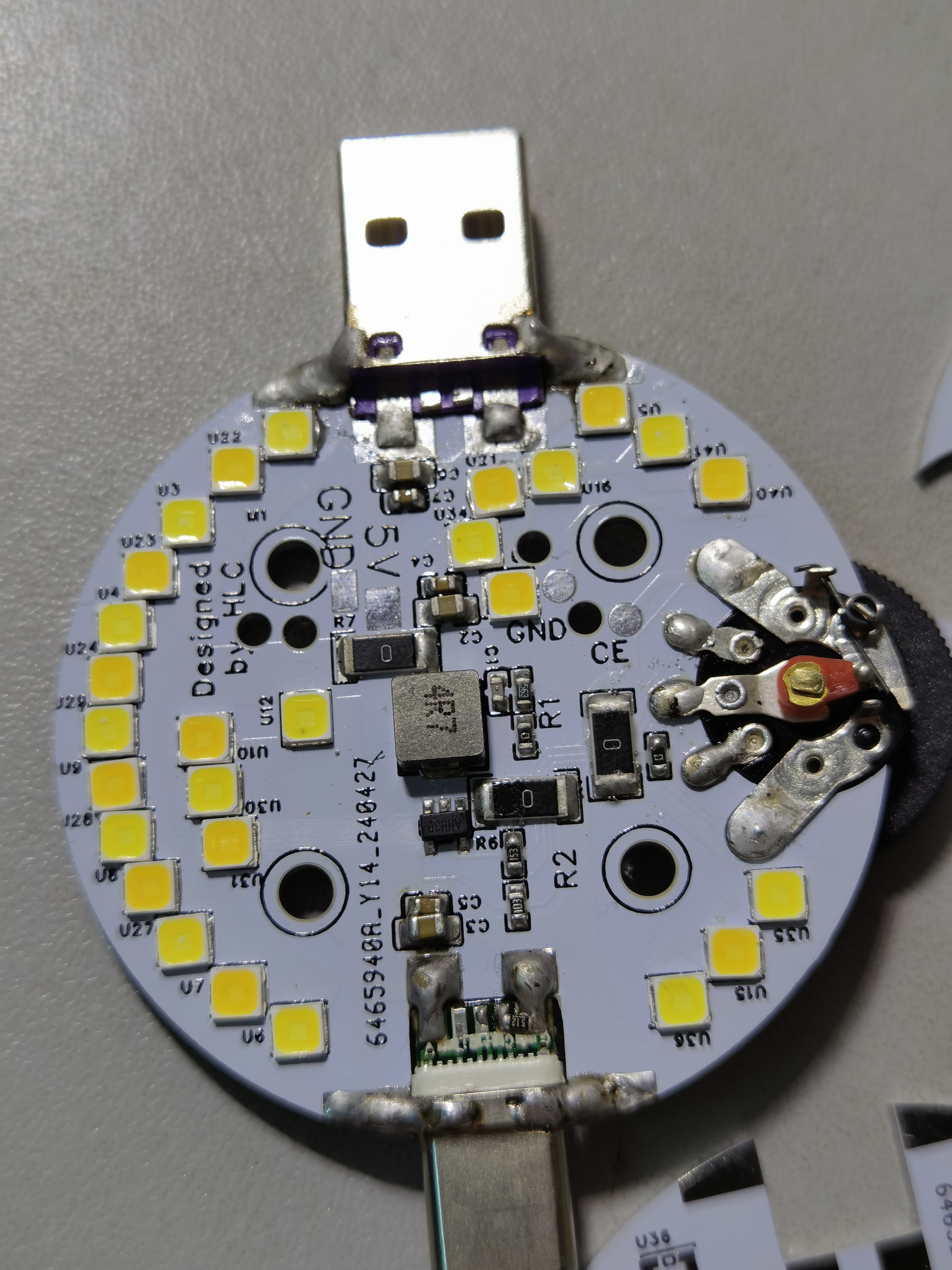
USB-A and Type-C dual-port adjustable high-brightness portable LED light
This portable, high -brightness LED light features dual USB-A and Type-C ports and stepless dimming
. The brightness can be adjusted to a very low level, making it suitable for use in dorm rooms after lights out. With
a maximum brightness of approximately 6W
, it's dozens of lumens brighter than a phone flash, ensuring you're the brightest person around when you're running at night.
The 2510 specification 5V cooling fan is optional; if you choose to install it, you will need to purchase M3*18 countersunk screws and nuts.
**Important!
** Use the RV12mm flat-pin radio dial potentiometer to adjust the light intensity.
Purchase a male Type-C connector with a CC terminal and its accompanying board. Solder a 5.1k resistor between the CC and GND terminals for output. **
Main Components:
** **Effect:**
A demonstration video is attached.
VID_20240502_204605.mp4
PDF_USB-A, Type-C Dual-Port Adjustable High-Brightness Portable LED Light.zip
Altium_USB-A, Type-C Dual-Port Adjustable High-Brightness Portable LED Light.zip
PADS_USB-A, Type-C Dual-Port Adjustable High-Brightness Portable LED Light.zip
BOM_USB-A, Type-C Dual-Port Adjustable High-Brightness Portable LED Light.xlsx
94612
MSPM01306 Core Board
Core board based on MSPM01306VQFN-32 design
Based on the MSPM01306, with an appearance reference to the SMT32C8T6, it features an onboard serial-to-USB converter, two user buttons, a reset button, and a tri-color LED. All pins are exposed, with five wires reserved for XDS110 connection and simulation. A separate four-wire OLED screen interface is also included. Costs are kept to a minimum, using a double-layer PCB with components distributed on only one side for easy soldering. The tri-color LED
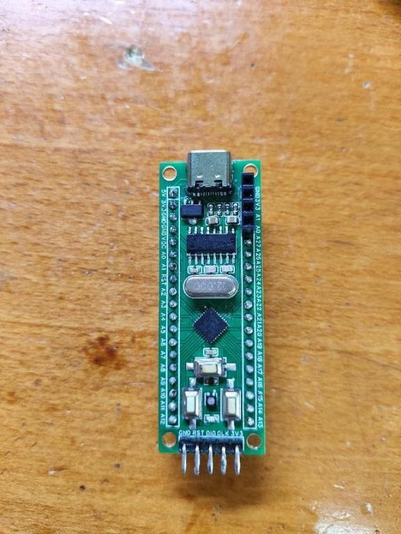
on the front of the PCB
is connected to PA11, 12, and 13. The buttons are connected to PA14 and 18. The buttons do not have pull-up resistors; these can be added if needed.
[【Open Source】DIY MSPM0 Minimum System Board Sharing] Bilibili Introduction
msp430m0_1306_OLED display.zip
PDF_MSPM01306 core board.zip
Altium_MSPM01306 core board.zip
PADS_MSPM01306 core board.zip
BOM_MSPM01306 Core Board.xlsx
94614
[Verified] ROS car control module based on STM32F103RCT6
This is a control module based on the STM32F103RCT6. The hardware design references products from several ROS robot manufacturers on the market and has been verified.
The product design is primarily intended for use with the project https://oshwhub.com/danxinzhe/dian-yuan-ban-gai-ban. To reduce development costs, I manufactured the core board and control board separately. This minimizes losses due to design errors. Once the control board is completed, it can be used for simple driver testing with a microcontroller. After confirming that there are no issues, the core board will be manufactured. To reduce size and simplify wiring, the core board uses a 4-layer design.
The onboard MPU6050 and INA219 have been verified to be able to collect robot posture and battery data in real time. The battery is powered by 12V. The board also features two USB-to-serial adapters using CH9102F. This board is small and inexpensive, includes an automatic download circuit, and allows for code debugging via the SWD port. It can be directly connected to a Linux host computer via a Typc interface, which is very convenient. The
code is largely based on the code from Yabo Intelligent Technology's car, as the pin definitions are mostly designed accordingly. The main appeal of designing and tinkering is the fun. A purchased board might cost around 300 RMB, while a self-built one would cost around 100 RMB. The components are not very expensive.
The lower-level machine code adaptation is complete; other specific algorithms still need further refinement.
It features a multi-button layout and an OLED screen, making it a viable development board. It also supports RGB light strips, which have been successfully tested. A serial port is provided for connecting WiFi or Bluetooth, allowing for remote-controlled car functionality. That's all for now.
The automatic download circuit has a minor issue, but it's not a major problem; the SWD interface should be ignored. Two videos have been uploaded showing how to use the module; the basic functions are now implemented.
584175755df631d68b8fd200a5cfeec3.mp4
b248be9fc4e68e96c3c5bdde014db0b4.mp4
PDF_【Verified】ROS Car Control Module Based on STM32F103RCT6.zip
Altium_【Verified】ROS Car Control Module Based on STM32F103RCT6.zip
PADS - [Verified] ROS Car Control Module Based on STM32F103RCT6.zip
BOM_【Verified】ROS Car Control Module Based on STM32F103RCT6.xlsx
94615
GD32F103 Verification Board
The STM32F103RCT6 minimum system board developed by LCSC was validated.
This diagram is primarily based on LCSC's minimum system board with some adjustments. The adjustments were made to address missing components, utilizing available parts. The Type-C interface was changed to a micro connector, and four cross bracket holes were added. To avoid unforeseen circumstances, the rest of the design was retained as much as possible from LCSC's original design; we express our gratitude to them!
PDF_GD32F103 Verification Board.zip
Altium_GD32F103 verification board.zip
PADS_GD32F103 verification board.zip
BOM_GD32F103 Verification Board.xlsx
94616
electronic

 This is a C8T6 main controller for a small car/drone remote control, using a Ci24R1 for communication. It includes basic code for various functions such as button detection, remote sensing monitoring, communication, flashing lights, and OLED display. Discussion and guidance are welcome. (Group number: 289917684)
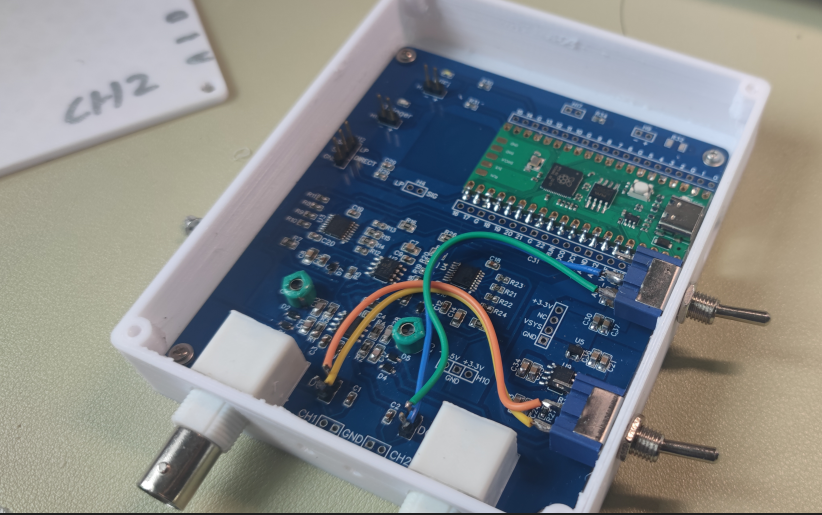


 京公网安备 11010802033920号

 BL-D50C-21YO


