I. Module Parameters
Rated Input: DC 9V-20V
Rated Output: +5V 1.5A -5V 1A (output voltage can be modified)
Size: 3.2cm*3cm
II. Soldering Tutorial
Please use the BOM information exported from the project!!! Please use the BOM information exported from the project!!! Please use the BOM information exported from the project!!! The BOM automatically generated in the open-source interface may have errors.
Component Selection Notes:
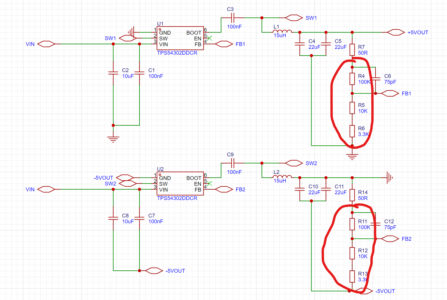
Chip: Uses TI's TPS5420 step-down chip, nominal rated output current 2A. TPS5430 can also be used instead, nominal rated output current 3A, pin and peripheral circuit fully compatible, but slightly more expensive.
Capacitor: If operation is required at a maximum input voltage of 20V, the input filter capacitor (10uF) needs to be a 1206 package capacitor with a voltage rating of 35V or higher. It is also recommended to leave a 5V margin for the output filter capacitor (22uF), for example, when outputting 5V, it is recommended to use a 0805 package capacitor with a voltage rating of 10V or higher.
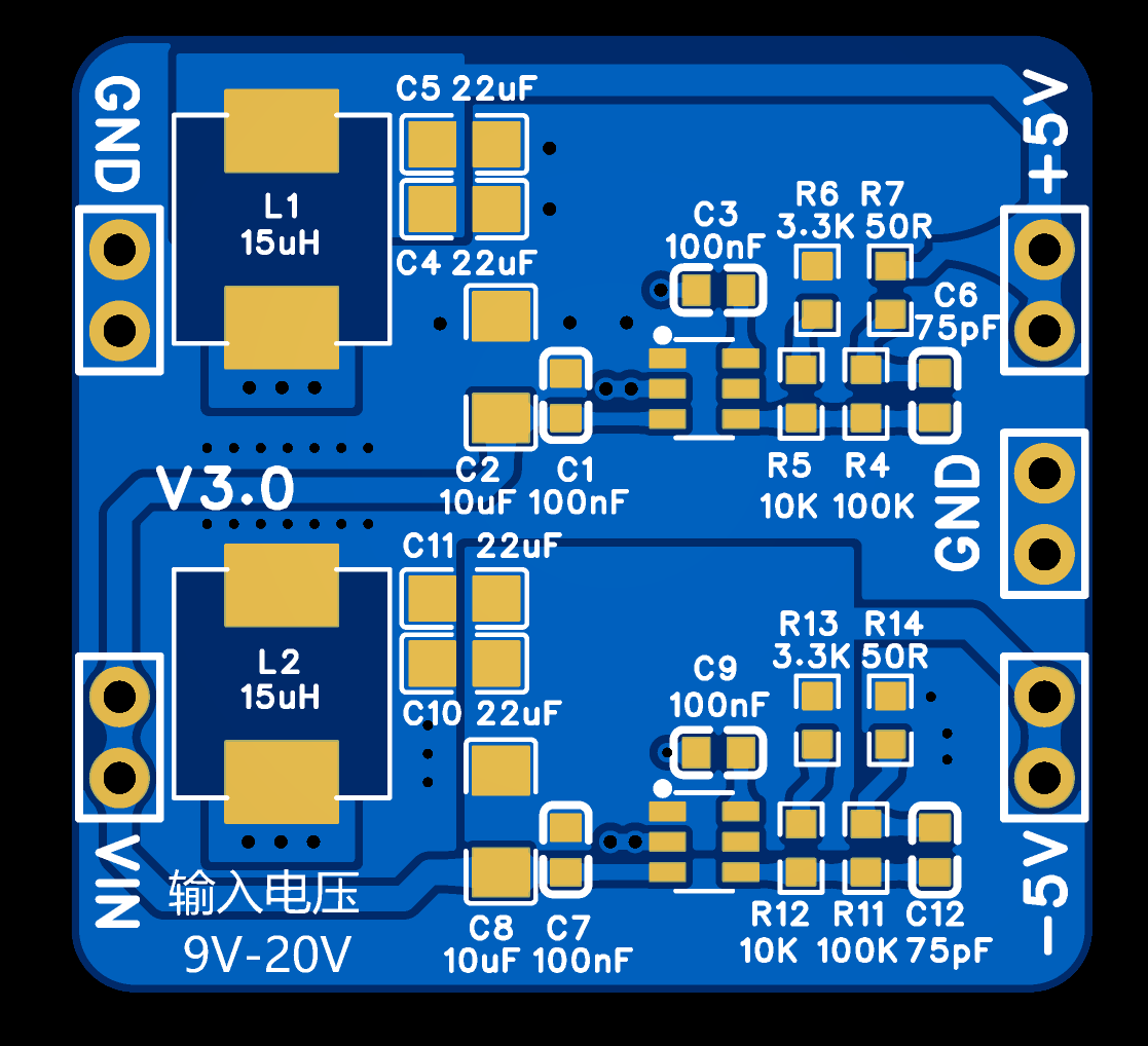
Inductor: A molded shielded inductor in a 0630 package with an inductance of 15uH is sufficient.
Resistor: A 0603 package is recommended; 1% precision resistors are suggested to ensure accurate voltage settings.
The module uses all surface-mount components; a heated board or hot air gun is recommended for soldering (easier). Component parameters are marked on the board; refer to the silkscreen to solder the corresponding components. The module's GND pads are fully filled with copper for faster heat dissipation; pay special attention to avoid cold solder joints during soldering.
In this design, the output voltage is 5V. To change the output voltage, modify the voltage divider resistors (R4-R6, R11-R13). The output voltage is set by the following formula:
Vout=0.596*{R4/(R5+R6)+1}. For example, to set the output to 9V, R4 can be 100kΩ, R5 5.1kΩ, and R6 2kΩ. For details on voltage settings and component selection, please refer to the TPS5420 chip datasheet.
III. Precautions for Use
When using this module, please ensure good heat dissipation and do not exceed the rated input voltage. This module is a buck converter; the input voltage must be higher than the set output voltage, otherwise it will not output properly.
The open-source project includes a package file, which can be used to solder the module onto other PCBs requiring power using headers.
IV. Remarks
This is the first open-source electronic module; due to limited experience, errors and omissions are inevitable. Any comments or suggestions are welcome. ~
Actual product image:

BOM_Positive and Negative Power Supply Module.xlsx
TPS5420.pdf
Positive and negative power supply module package.elibz
The PDF_TPS5420 positive and negative power supply module can be used to power operational amplifiers. (zip file)
The Altium_TPS5420 positive and negative power supply module can be used to power operational amplifiers. (zip)
The PADS_TPS5420 positive and negative power supply module can be used to power operational amplifiers. (zip file)
The BOM_TPS5420 positive and negative power supply module can be used to power operational amplifiers. (xlsx)
94735
Intelligent cockpit based on LCSC Taishanpai
Desktop in-vehicle system based on Taishanpai
Based on the [LCSC Taishanpai] Smart Cockpit
: I) Preliminary Preparations:
1. Install VMware virtual environment for development.
2. Install Ubuntu, configure system environment, and install development tools.
3. Download Android source code, compile U-Boot, kernel, and system, and create an image for flashing.
Note: The Ubuntu version cannot be too high, otherwise the Android source code will fail. Ubuntu 18.04 is recommended.
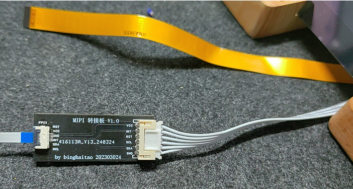
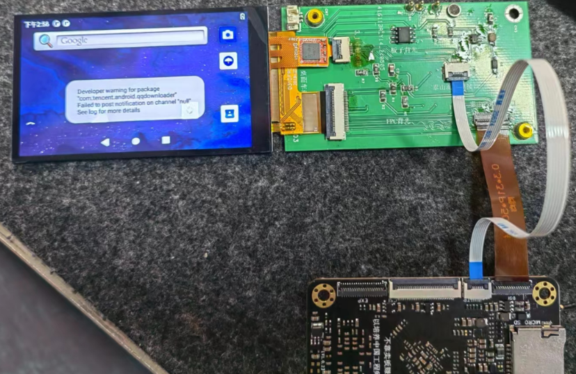
II) MIPI Screen Debugging:
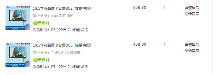
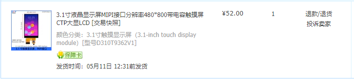
1. Purchase a MIPI screen
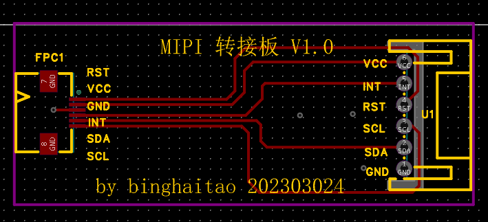
. 2. Draw the MIPI connection to the Taishanpai adapter board.
3. Debug the device tree (DTS) and compile the kernel.
4. Create a boot.img image and flash it.
5. Successful debugging; quite rewarding.

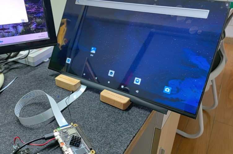
III) EDP Screen Debugging and Verification:
1. Purchase an EDP screen

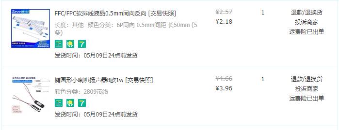
. 2. Purchase a connection cable, connect to the Taishanpai, and install according to requirements.
3. Configure the DTS device tree according to the hardware manual, compile the kernel, and flash it.
4. Successful compilation and flashing in one go.
During II and III, note that the boot.img file may not take effect after kernel compilation and flashing. You can try adding some errors to the DTS file and then compiling to see if there are any errors. Then remove the errors, recompile and flash the firmware.
(IV) Taishanpai Smart Cockpit Design:
1. Draw the schematic diagram

; 2. Design the PCB:
First attempt at differential circuit design, 4-layer circuit, impedance calculation method;
3. Purchase components

, solder the circuit diagram,
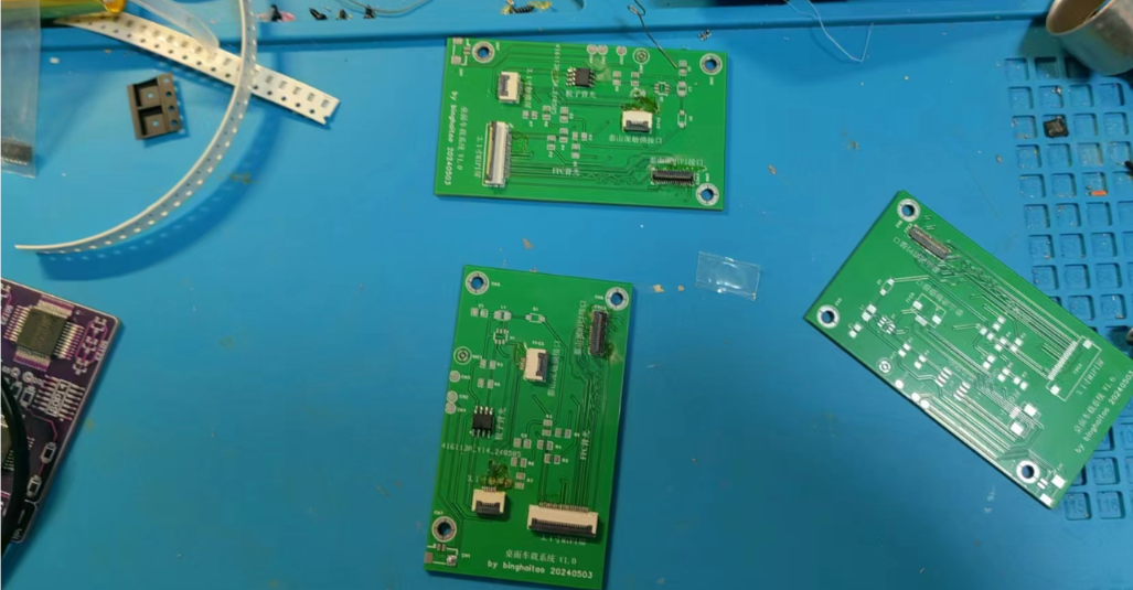
and flash the firmware after soldering.

This training camp was indeed challenging for soldering; this time, a heating table was used to solder difficult components and connectors.
Debugging drivers and
developing your own desktop platform application software.
Taishan Sect 1.mp4
PDF_Smart Cockpit Based on [LCSC Taishanpai].zip
Altium_Smart Cockpit Based on [LCSC Taishanpai].zip
PADS_Smart Cockpit Based on [LCSC Taishanpai].zip
BOM_Intelligent Cockpit Based on [LCSC Taishanpai].xlsx
94736
M3C chip 86-box design ZX3D95CM20S
M3C chip 86-box design ZX3D95CM20S-V14
This is an 86-box motherboard using the ZX1H04-R4 chip.
It employs an ESP32-C2 Wi-Fi module, allowing for custom development or development using AT commands.
The LCD screen has a 480*480 resolution, RGB interface, and touch functionality.
It also includes a temperature and humidity sensor, mono audio output, and RS485.
[Link: https://item.taobao.com/item.htm?id=765227233288 ]
Actual product image.png
PDF_M3C Chip 86-Box Design ZX3D95CM20S.zip
The Altium M3C chip 86-pack design is available in ZX3D95CM20S.zip.
PADS_M3C chip 86-box design ZX3D95CM20S.zip
94737
electronic


 京公网安备 11010802033920号

 CWR09FK105JCC


