
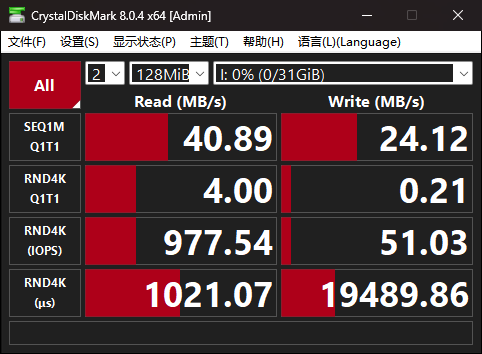
 The left image shows a direct connection to the computer, while the right image shows five
  USB2 ports connected in series with the hub before connecting to the computer. The left image shows a direct connection to the computer, while the right image shows three USB3 ports connected in series with the hub before connecting to the computer. Connecting four USB3 ports in series is unstable, and five ports are not recognized.
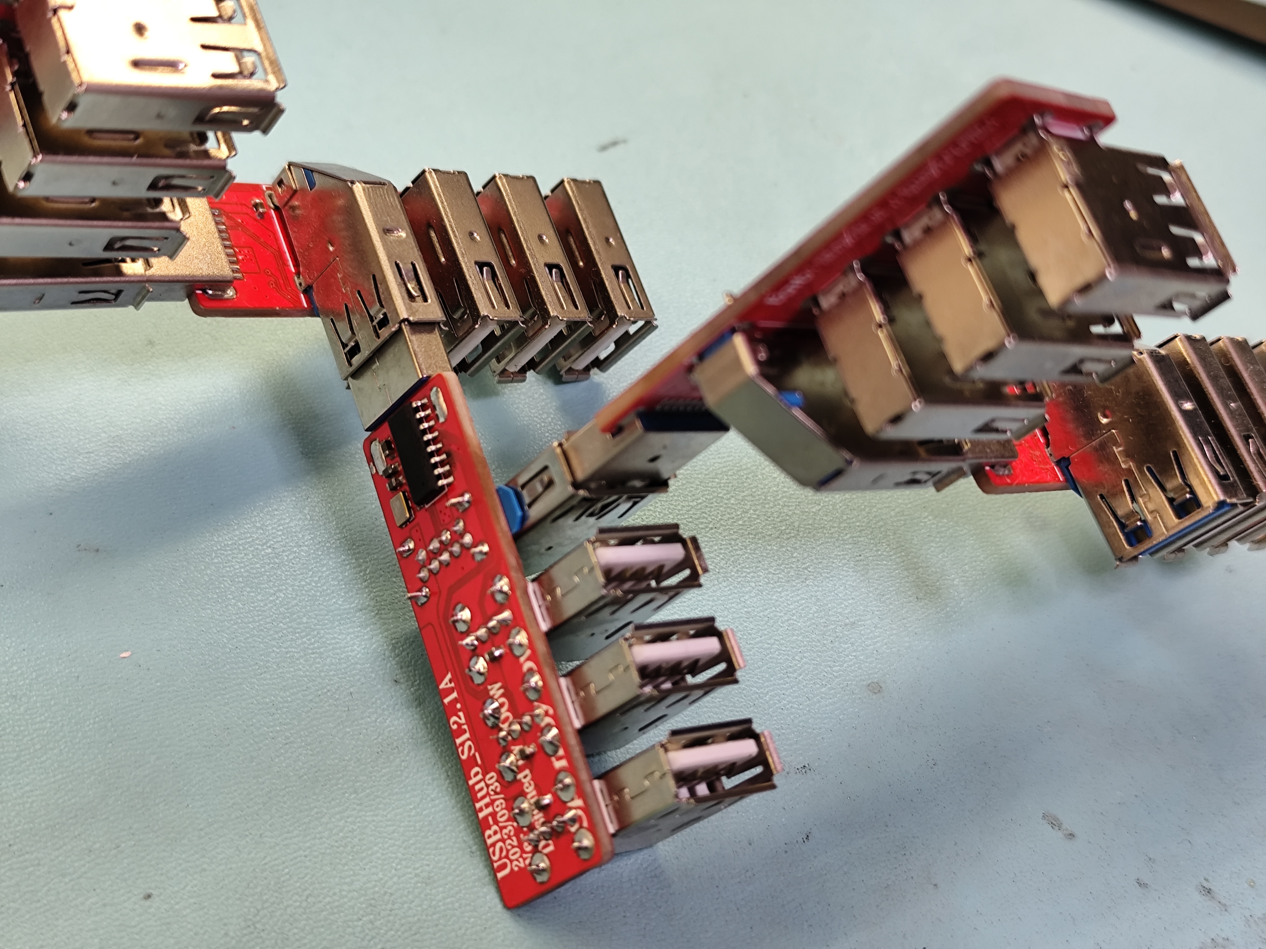

 2. Serial Port Chip: Changed to CH304X, with a smaller package
  . 3. USB: Changed to Micro USB for wider compatibility, with a larger package than the original. In fact, this larger USB port caused a misalignment between the PCB and the screen casing size at the USB port. My first version forgot to consider this, resulting in a gap in the casing at the USB port. However, in this open-source version, I've tried to make the USB port fit the casing size as closely as possible; it might only require trimming a small corner with pliers.
  4. Freewheeling/Zen Regulator Diode: Replaced with MBR0540, with similar parameters and a similar package size to the original diode. It has been tested and works.
  5. Other modifications:
  VIII. Physical Display

All reference designs on this site are sourced from major semiconductor manufacturers or collected online for learning and research. The copyright belongs to the semiconductor manufacturer or the original author. If you believe that the reference design of this site infringes upon your relevant rights and interests, please send us a rights notice. As a neutral platform service provider, we will take measures to delete the relevant content in accordance with relevant laws after receiving the relevant notice from the rights holder. Please send relevant notifications to email: bbs_service@eeworld.com.cn.
It is your responsibility to test the circuit yourself and determine its suitability for you. EEWorld will not be liable for direct, indirect, special, incidental, consequential or punitive damages arising from any cause or anything connected to any reference design used.
Supported by EEWorld Datasheet
EEWorld
subscription
account

EEWorld
service
account

Automotive
development
community

Robot
development
community

About Us Customer Service Contact Information Datasheet Sitemap LatestNews


Room 1530, 15th Floor, Building B,
No.18 Zhongguancun Street,
Haidian District,
Beijing, Postal Code: 100190
China
Telephone: 008610 8235 0740
 京公网安备 11010802033920号

 NRWS1R0M6.3V12.5X20F


