Based on @ylj2000's open-source modification, using 0603 packaging for easy soldering
of original project addresses. High-speed wireless DAP debugger - JLCPCB EDA open-source hardware platform (oshwhub.com)
This is a test module for the MGA-81563 RF LNA chip.
The MGA-81563 is a low-noise RF amplifier ranging from 0.1 to 6 GHz. This module is used to test the chip and can also be used as a front-end signal amplification module for various SDRs or other RF receivers.
Frequency range: 0.1~6 GHz.
Gain: 12.4 dB.
IP3: 27 dB.
A constant current source provides a stable current, unaffected by load changes or power supply voltage fluctuations. Constant current sources are widely used in LED lighting. The following projects include both offline constant current and DC-DC constant current sources. Due to the author's limited expertise, this article may contain flaws; readers are kindly requested to offer their criticism and corrections.
Reproduction without the author's permission is prohibited!
Since its invention in the 1960s, the photodiode has revolutionized lighting and display technology with its high efficiency, durability, and environmental friendliness.
An LED is a semiconductor device that converts electrical energy into light energy. Its high efficiency, energy saving, environmental friendliness, and long lifespan have led to its widespread application in lighting, displays, and signal indication. LEDs emit light by driving electrons and holes to recombine at a PN junction through current. This electroluminescence effect makes LEDs play a crucial role in energy-saving lighting and high-brightness display technologies. The color of LED light emission depends on the bandgap of the semiconductor material used. By adding phosphors to the LED package, the emitted light can be converted or enhanced, producing different colors, especially for manufacturing white LEDs. The use of phosphors not only improves the luminous efficacy and color quality of LEDs but also helps reduce costs and extend their lifespan.
LEDs typically require a constant current source because the brightness of an LED is proportional to the current passing through it, and a constant current source provides a stable current, ensuring the consistency of the LED's brightness and color. Furthermore, a constant current source helps protect LEDs from damage caused by excessive current by limiting operating current, reducing heat loss and extending LED lifespan. It also facilitates effective thermal management, reduces electromagnetic interference caused by current fluctuations, and improves the overall reliability of the LED lighting system. Moreover, constant current driven LED systems can achieve dimming functionality through pulse width modulation (PWM) or analog dimming technology without significantly altering the LED's color temperature and efficiency. Therefore, a constant current source is a key factor in ensuring the performance and lifespan of an LED lighting system.
When selecting LEDs, the following parameters should be considered:
Luminous flux: This is a physical quantity describing the total light output of a light source, measured in lumens. It represents the total amount of visible light energy emitted by the light source per unit time and is a key parameter for evaluating LED lighting efficiency. Higher luminous flux means more light energy emitted by the light source, but it does not directly reflect light intensity or lighting effect, as these are also affected by factors such as beam angle, viewing distance, and ambient light. When designing a lighting system, luminous flux is an important basis for determining the required number and type of LEDs.
Luminous intensity: Commonly known as light strength, it is a physical quantity describing the luminous performance of a light source in a specific direction, measured in candela (cd). It represents the luminous flux of a light source per unit solid angle and is related to the emission angle and direction of the light source. Luminous intensity is affected by factors such as the LED's construction, optical design, and drive current. When designing a lighting system, considering luminous intensity helps determine the required number and layout of LEDs to achieve the desired lighting effect. Furthermore, luminous intensity is one of the key indicators for evaluating LED performance and comparing the brightness of different LED products.
Emission angle: This parameter describes the divergence of the LED beam, defining the width of the emitted light and affecting the coverage and concentration of the lighting. A smaller emission angle produces a more concentrated beam, suitable for local lighting or spotlighting; a larger emission angle provides wider illumination, suitable for floodlighting.
Forward voltage: Also known as the voltage bin, it is the minimum voltage required for an LED to operate normally, determining the LED's conduction conditions. This voltage is affected by factors such as semiconductor materials, manufacturing processes, and ambient temperature, and decreases as temperature increases. The stability of the forward voltage is crucial to the performance and lifespan of an LED. Excessive voltage can lead to overheating, while insufficient voltage will prevent the LED from functioning properly. When designing LED driver circuits, the forward voltage must be considered to ensure stable operation of the LED under the control of a constant current source. The forward voltage may differ for LEDs of different colors; this information is usually provided in the product datasheet.
Forward current: This is the current flowing through the LED's terminals during normal operation and is a key parameter ensuring LED illumination. It is usually measured in mA and is directly related to the LED's brightness; generally, the higher the current, the brighter the LED. However, excessive current can cause the LED to overheat and shorten its lifespan, so it must operate within the LED's maximum rated current range.
Color temperature: This is a physical quantity describing the color characteristics of a light source, measured in Kelvin (K). It reflects the temperature at which the color of light emitted by the light source matches the color of light radiated by a black body at a specific temperature. A lower color temperature results in a warmer, yellowish light, giving a warm and comfortable feeling; a higher color temperature results in a cooler, white light, giving a clear and calming feeling. For example, home lighting may prefer warm white light, while office lighting may choose natural white or cool white light. Choosing the correct color temperature is crucial for creating a suitable lighting environment and improving visual comfort.
Color Rendering Index (CRI): This measures a light source's ability to reproduce the colors of objects, ranging from 0 to 100. A higher CRI value indicates better color reproduction under illumination, closer to the colors under natural light. The CRI value of LED lights is usually indicated on the packaging or in the technical specifications. High CRI LEDs reproduce colors more realistically and are suitable for places where color accuracy is critical, such as art galleries and retail displays.
Thermal Resistance: This is a physical quantity that measures the heat dissipation capability of an LED device, usually expressed in degrees Celsius per watt (°C/W). It describes the difficulty of heat transfer between the LED and its surrounding environment per unit power. Lower thermal resistance indicates more efficient heat transfer and better heat dissipation performance. High thermal resistance leads to increased LED chip temperature, affecting its luminous efficiency and lifespan.
Efficiency: Usually expressed in lumens per watt (lm/W), this measures the efficiency with which an LED converts electrical energy into light energy. High efficiency means that an LED can produce more light output while consuming the same amount of electricity. Efficiency depends on the materials, design, and manufacturing process of the LED. High-efficiency LED lamps not only save energy but also reduce heat generation and extend product lifespan.
Wavelength: A physical quantity describing the color characteristics of light, measured in nanometers (nm). The light emitted by an LED has a specific wavelength, which determines its color. Different wavelengths correspond to different colors; for example, red light has a wavelength of approximately 620-750nm, green light approximately 495-570nm, and blue light approximately 435-500nm.
Operating temperature range and junction temperature: These are important parameters of LEDs, affecting their performance and lifespan. The operating temperature range refers to the ambient temperature range within which an LED can operate normally, while the junction temperature is the highest temperature that an LED can reach internally. Suitable operating temperature and low junction temperature help maintain the brightness and color of the LED, preventing performance degradation and damage. Commonly
used LED chip manufacturers include:
Osram, Jinko Electronics, Refond Optoelectronics, Hongli Zhihui, Shengpu Optoelectronics, and Suijing Optoelectronics. Constant current source: A constant current source is a power supply mainly used to provide a constant current, maintaining a stable current even under load changes or power supply voltage fluctuations. In LED lighting systems, constant current sources are crucial for protecting LEDs, improving system efficiency, extending LED lifespan, and enabling dimming functionality. Precise current control prevents LED damage from overcurrent, ensuring safe operation. Constant current sources are simple to design, cost-effective, and highly flexible, making them suitable for various LED applications, including general lighting, landscape lighting, and automotive lighting. Constant current sources are categorized as follows:
Linear constant current: Linear constant current can be achieved using transistors, typically two transistors in a complementary configuration. Both transistors are placed in the amplification region, where their voltage-current characteristic curves approximate a straight line, hence the name linear constant current. Excess reactive power is consumed by the power transistors, leading to significant transistor heat generation. This makes it unsuitable for high-power applications due to its low efficiency. Its advantage is flicker-free operation. The schematic is shown in Figure 1-1. The linear constant current source uses two transistors to form a complementary constant current source. Q2 acts as the regulating transistor, ensuring that the power transistor Q1 always operates in the amplification region. R1 is a current sampling resistor with a voltage of 0.7V across it. Therefore, the constant current value is the voltage across the sampling resistor divided by its resistance: I = 0.7V/R1. The specific working principle is as follows: When power is applied, R2 acts as a pull-up resistor, directly applying the power supply voltage to the base of Q1 after current limiting through the resistor. At this time, transistor Q1 enters the saturation region. Since the sampling resistor R1 has a certain resistance value, after the current flowing through it reaches a certain value, the voltage across the sampling resistor gradually increases to about 0.7V. At this time, the voltage reaches the turn-on voltage of the regulating transistor Q2 and then enters the amplification region. After entering the amplification region, the base voltage initially applied to the power transistor Q1 decreases to about 1.4V and remains constant, thus completing a constant current closed loop. By changing the resistance value of R1, the magnitude of the constant current can be set. No matter how the input voltage changes, the current is always the set value. Only when the input voltage is lower than the output voltage plus the turn-on voltage of the power transistor, the constant current condition is not met, and it will not work in the constant current region. As shown in Figure 1, the sampling resistor has a resistance of 4.7R, and the voltage across it is 0.549V. I = 0.549V/4.7R, so the current is 116mA. The output voltage is the voltage drop across the LED, 7.17V. The input voltage must be higher than the output voltage (7.17V + 0.8V) for this circuit to function properly. Important points to note: The resistance of R2 must be considered; it cannot be too large or too small. The power dissipation of the sampling resistor R1 must be taken into account; if the power dissipation is insufficient, multiple resistors need to be connected in parallel.
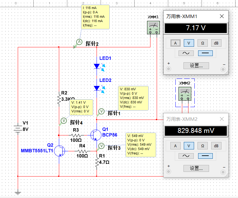
Figure 1-1
shows the actual circuit, as shown in Figure 2-1. In


Figure 2-1
, Q1 is an MMBT5551, Q2 is a BCP56, the LED is a Jinko Optoelectronics AG2-X7, and the capacitor uses X7R material.
LM317 Constant Current Source: The LM317 is a multi-functional three-terminal linear regulator that can be used to build constant current source circuits, widely used in LED driving and constant voltage applications. The foundation of constructing an LM317 constant current source is to utilize its internal 1.25V reference voltage. A sampling resistor is connected in series between the output and adjustment pins to set the constant current value. According to Ohm's law, the output current can be calculated using the formula I = 1.25/RCS. For example, if a constant current output of 25mA is required, a 50Ω sampling resistor can be selected. This is shown in Figure 2-2.
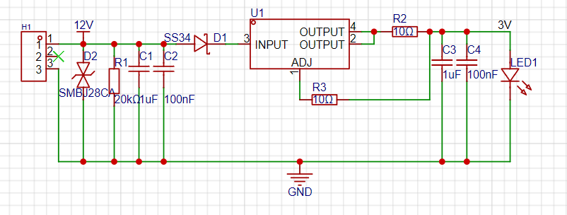

Figure 2-2
Op-amp + MOSFET Constant Current Circuit: The constant current source circuit constructed by combining an op-amp and a MOSFET maintains a stable output current through a precise feedback control mechanism. The core of this circuit is an operational amplifier. Its non-inverting input receives a stable reference voltage, while its inverting input is connected to the drain of the MOSFET through a sampling resistor. The current flowing through the MOSFET generates a voltage drop across the sampling resistor. The operational amplifier compares this voltage with the reference voltage and adjusts the MOSFET's gate voltage through its output, thereby controlling the drain current. When the current increases, causing the voltage drop across the sampling resistor to rise, the operational amplifier output decreases, reducing the MOSFET's conduction level, and vice versa, ensuring that the current remains constant. To improve circuit stability, a compensation capacitor is typically added to the feedback loop to filter out high-frequency noise and prevent oscillation. The on-resistance and maximum current handling capability of the MOSFET must also be considered during circuit design. If the application requires high temperature stability, a temperature compensation mechanism must be added to reduce the impact of ambient temperature changes on the constant current output. See Figure 2-3 below.

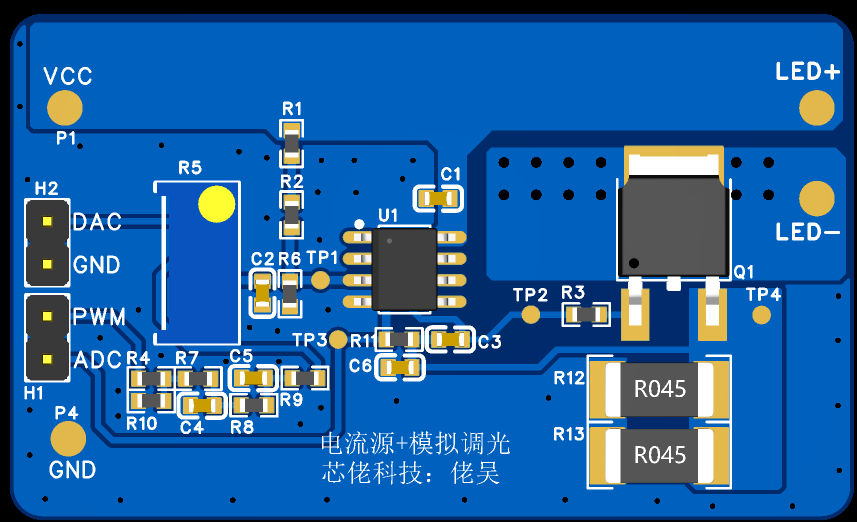
Figure 2-3
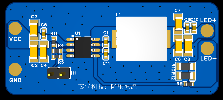
: Buck DC-DC Constant Current: The buck DC-DC constant current circuit is a highly efficient power conversion scheme that controls current flow by periodically switching the MOSFET, thereby generating a stable current at the output. The circuit typically includes an inductor to store energy, a capacitor to smooth the current, and a feedback network to monitor and regulate the output, ensuring that the constant current output is unaffected by input voltage fluctuations and load changes. Due to its high efficiency and good stability, it is widely used in LED lighting, battery charging, and other applications.
Taking the LN33061 chip as an example, it is a high-efficiency, high-density buck LED driver. This LED driver uses a fixed-frequency peak current control mode with internally integrated loop compensation. This device has an input voltage range from 3.5V to 60V, integrates high-side and low-side power MOSFETs, and can drive maximum load currents of up to 0.6A, 1A, and 1.5A. Switching frequency options include 400kHz, 1MHz, and 2.1MHz. Pulling the EN pin directly up allows the chip to output at maximum current. It can also operate in PWM mode if PWM is applied. The current magnitude is set by adjusting the sampling resistor value via the FB pin; the input must be greater than the output. Detailed operating principles can be found in the datasheet or on the official website and will not be elaborated here. See Figure 3-1. Figure 3-1:

DC
-DC Boost Constant Current: When the output voltage is higher than the input voltage, a boost circuit must be selected. Since LEDs are current-driven components, a boost constant current circuit is required. Taking the MPS MPQ3362 boost constant current chip as an example, the input is 3V-36V/4A, and the maximum output voltage is 36V, as shown in Figure 4-1.
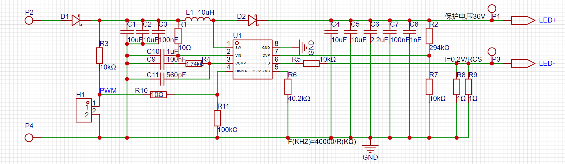
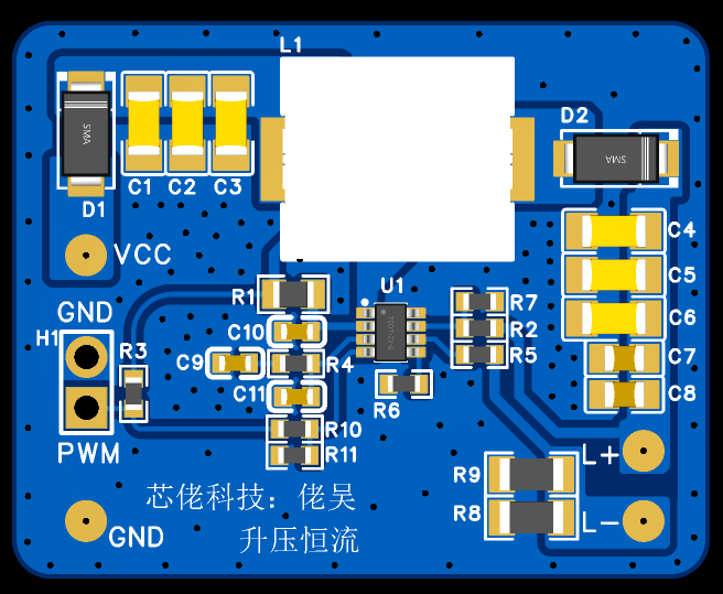
Figure 4-1
The original 2.4-inch Miyoo horizontal handheld console has been upgraded to a 3.2-inch Miyoo horizontal handheld console.
First, here's the link to the original project: https://oshwhub.com/sunnygold/2.4cun-Miyooheng-ban-zhang-ji Thanks to the original open-source project released by "Don't Disappoint!" Updated April 30, 2024:
New board design, supports dome switches and conductive adhesive, casing appearance resembles the 35B, hardware switch replaced with EC1970707.


The project files here are not updated; to get the new version, you need to join group: 514419296.
Old description:
This project only modified the board size and made minor cosmetic changes such as adjusting the positions of some components and screen wiring.
The board has been prototyped and tested, and can be overclocked up to 1400MHz with normal functionality.
The casing files have also been prototyped and tested.
The screen refreshes smoothly at 60 frames per second without tearing. It supports
the following game consoles and arcade emulators: GB, GBC, GBA, FC, SFC, MD, PS1, G&W, MAME, NEOGEO, FBA,
and some less common emulators: Java, MSX, NGP, PCE, PICO-8, VECTREX, WSWAN, Z80, and Wenquxing.
The motherboard is only 1.6mm thick

, nothing more to say.


The 3.2-inch screen features a 3.2-inch TFT LCD screen with parallel and serial ports and IPS capacitors.
PDF_Original 2.4-inch Miyoo horizontal handheld console modified to 3.2-inch Miyoo horizontal handheld console.zip
Altium_original 2.4-inch Miyoo horizontal handheld console modified to 3.2-inch Miyoo horizontal handheld console.zip
PADS_Original 2.4-inch Miyoo horizontal handheld console modified to 3.2-inch Miyoo horizontal handheld console.zip
BOM_Original 2.4-inch Miyoo horizontal handheld console modified to 3.2-inch Miyoo horizontal handheld console.xlsx
Design of an MPU accelerometer based on PCB spiral architecture copper-clad capacitance detection technology
Demonstration video of MPU accelerometer design based on PCB spiral architecture copper-clad capacitance detection technology
: https://www.bilibili.com/video/BV15r421u72u/
Principle introduction: When a soft object is subjected to sufficient acceleration, it will produce slight deformation, resulting in a displacement of a very small gap. Since capacitance is related to the area, distance, and dielectric of the electrode plate, a change in capacitance will occur when the dielectric and area remain constant. By detecting the capacitance, the degree of deformation of the object can be obtained, and thus the acceleration can be measured.
Therefore, it is necessary to first design an object that is easily deformable. PCB is an excellent material (it's readily available). However, FR-4 is relatively rigid. We know that steel bars are very hard, but a 10-meter-long steel bar is easily deformed. Therefore, it is necessary to find a way to extend the length of the PCB. However, if it exceeds 10cm, it cannot be used without a solution, so a more comprehensive approach is needed.
Ultimately, the PCB length was extended using a spiral slotting method, allowing the lengths of multiple consecutive sides to be superimposed to support the moving parts.

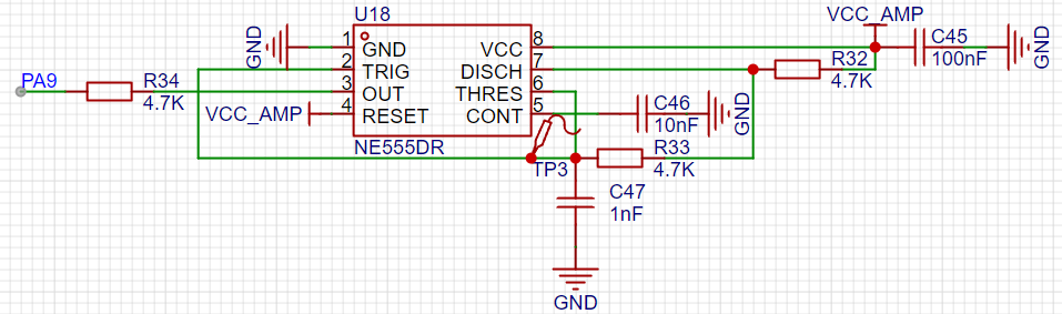
This board was then mounted very close to another copper-clad board (using only a thin spacer). When the board is subjected to acceleration, it deforms, causing a change in capacitance. To detect this capacitance change, an oscillation circuit was designed. In this circuit, the period of the oscillation changes as C47 changes, resulting in a PWM waveform that is affected by the capacitance value. The output is then connected to the PA9 pin of the microcontroller to detect the PWM period.
This circuit series was then drawn on another copper-clad board, and
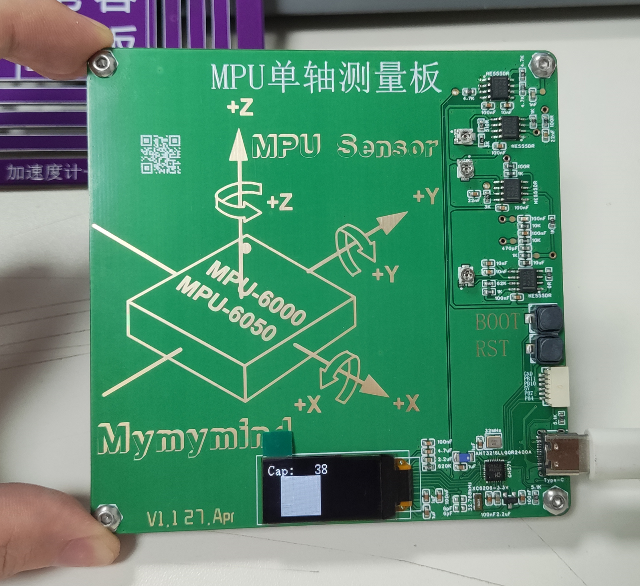
the two boards were finally mounted together. After writing the program, acceleration detection was achieved. Due to factors such as PCB material and microcontroller timer resolution, the final resolution was only 1.96 meters per second squared. The resolution could be further improved by replacing the PCB with a thinner one and using a microcontroller with a higher clock speed.


 京公网安备 11010802033920号

 15KP40A


