Brick Breaker, Spectrum Graph – Software Function Extensions for a Simple Oscilloscope Project
0 Introduction
This project implements oscilloscope, brick breaking, and spectrum graph functions. The hardware is a replica of the #JLCIC Training Camp##Simple Oscilloscope# project (GD32 version). It includes interesting peripherals such as analog signal acquisition, a TFT screen, and a rotary encoder, thus aiming to fully utilize hardware resources to enhance playability. Only the peripheral hardware and software are extended; the hardware itself remains unchanged. Those replicating this project can directly burn the software for a quick trial. Specifically: the oscilloscope project is a built-in function of the training camp project; the brick breaking is controlled using a rotary encoder, requiring no other peripherals; the audio spectrum graph is achieved by acquiring an external microphone amplifier module or headphone jack signal through analog signal acquisition, followed by FFT calculation.
1. Function Demonstration

1.1 Software Source Code and Hex File Download Address
The official GD32 project can be directly replicated. The source code
oscilloscope, spectrum diagram, and
pre-compiled hex file of the brick-breaking source code are in the attachments at the end of the article. You can directly burn them to use.
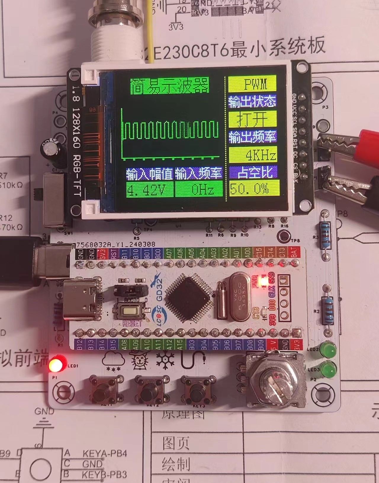
2. Simple Oscilloscope
(Official Built-in, Omitted)
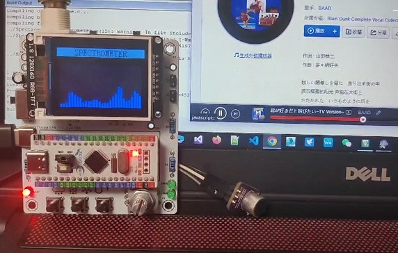
3. Spectrum Diagram
The oscilloscope example can already collect and display its own output PWM waveform signal, but for amateur hardware enthusiasts living in cramped conditions, there are too few places to make the oscilloscope function. How can we better make the hardware "wave"? It is easy to think of the ubiquitous sound waves and the spectrum that can follow the rhythm of sound waves.
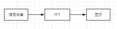
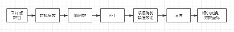
The core process of detecting and presenting the spectrum diagram is as follows:
3.1 Signal Interface - Headphone Plug or MAX4466 Microphone Preamplifier Module
The hardware front end is connected to the headphone plug with the oscilloscope probe. The headphone plug is connected to a mobile phone or other device to obtain the sound signal. However, this will depend on the playback device. The worst point is that the playback device cannot play sound after the headphone plug is plugged in. You can only choose one of listening to sound and viewing the spectrum. Therefore, a better choice is to use a microphone module. Here, the MAX4466 microphone preamplifier module (7.5 RMB on Taobao) was selected.
3.2 FFT Parameters - 2K 64 Points
Based on hardware conditions: GD32E230, 72MHz frequency, 8k RAM storage space, no FPU; characteristics of the sampled signal: the human ear's perceived frequency range is approximately 20~2KHz, with lower frequencies being more sensitive, ultimately determining 64 sampling points and a sampling frequency of 2KHz. If the sampling points were 256, a RAM limit error would occur, and compilation would fail. No further optimization methods were explored here, and 64 sampling points were used directly. This resulted in a maximum detection frequency of 1KHz, low frequency resolution, and mediocre performance. Those using microcontrollers with large RAM storage space can use 256 or higher sampling points to improve performance.
The audio signal acquisition process is similar to the oscilloscope signal acquisition process. The difference is that a 2KHz PWM is generated by configuring a clock to control ADC sampling, and the ADC sampled data is input to the DMA, with the DMA quantity set to 64. This allows the acquired signal to be retrieved in the DMA interrupt.
3.3 FFT Calculation
The FFT calculation process is arguably the most technically demanding part. Let's just list some prerequisite concepts for deriving FFT: natural base e, imaginary numbers, complex numbers, Euler's formula, Fourier series, Fourier transform, trigonometric orthogonality, Discrete Fourier Transform (DFT), butterfly transform, twitch factor... Stop reading! Stop reading...
Fortunately, this crucial algorithm is well-understood. We only need to learn the principles. The STM32 library functions can be directly called for the program part, and there are also highly optimized codes available online for reference. Here's an article I referenced:
FFT and IFFT source code implemented in C language, independent of specific platforms.
The basic principle is to use the twitch factor and butterfly transform to simplify the DFT calculation, reducing the complexity from O(n^2) to O(nlogn). Gauss and Cooley-Tukey are truly ingenious! The binary inversion and butterfly transform embody the divide-and-conquer approach.
In practice, to prevent frequency overflow during truncation, the input FFT data is windowed; this project uses a Hamming window. The output results require historical fusion filtering to make the spectrum jumps more consistent and flicker-free. To better match the characteristics of human ear spectrum perception, Mel transform and corresponding Mel scale display should also be added. For large differences in spectrum amplitude, logarithmic coordinates are used to adjust the displayed amplitude (20*log10(x)).
Algorithm summary:
3.4
The first data after the FFT output to the screen is a 0Hz DC component, which is removed during display. This project uses an ST7735 160x128 screen and calls TFT_FillRect to draw the spectrum.
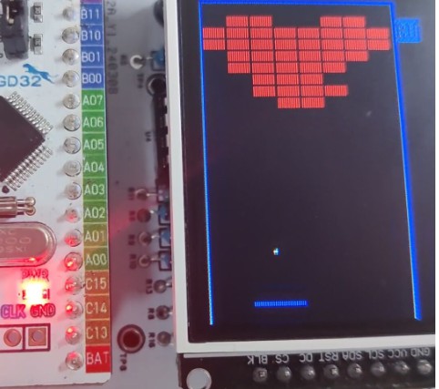
4
In the main interface of Brick Breaker, select BRICKBREAKER using the knob and press the knob to enter the game.
Gameplay: Move the platform using the knob and press the knob to fire. KEY1 speed adjustment (only effective during running and pause)
4.1 Basic Flow
The basic logic of the game's operation
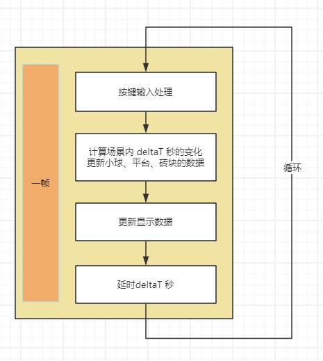
involves calculating changes within the scene. For Breakout, this mainly involves: the movement of the platform, the movement of the ball, and collisions between the ball and walls, platforms, and bricks.
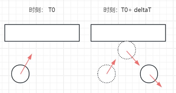
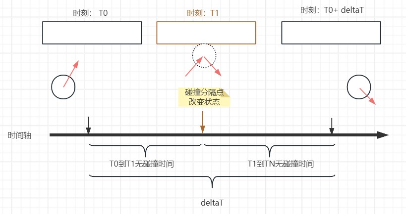
If there is no collision, the new position P' can be calculated using
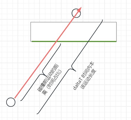
P' = P0 + V * deltaT , based on the current position P0, velocity vector V, and time deltaT. If there is a collision, how do we calculate the state after deltaT? We can treat the ball's trajectory within deltaT as a line segment and determine if this line segment intersects with the nearest block. If they don't intersect, there is no collision, and the calculation is complete; if they intersect, calculate the intersection point, the proportion of the intersection point to the line segment, and then calculate the collision time, changing the ball's velocity vector (simply changing the direction of movement). Next, repeat the above steps to further calculate until all calculations are completed within deltaT. In simple terms, it involves using the collision moment as the dividing point to change the ball's motion state within the time interval deltaT, recording the time between the collision points and the dividing points of the bricks that collided. The time consumed is calculated using a formula and distance. In the actual program calculation, a loop stepping method is used to calculate whether a collision occurs and its time consumption. 4.2 Simplified Collision Calculation : Judging a collision is relatively easy; it simply involves determining whether line segments intersect. This is even simpler in the brick-breaking game because only the ball's trajectory is arbitrary; the edges of the bricks, platforms, and walls are horizontal and vertical (aligned with the coordinate axes). For example, to determine if an upward-moving ball collides with a brick , it's sufficient to check if the start and end points of the ball's motion line segment are located above and below the bottom edge of the brick, respectively. If no, there is no collision; if yes, further judgment is made. For the case where yes in the previous step, the dividing point is found within the line segment. If the dividing point is outside the bottom edge of the brick, there is no collision; if inside, there is a collision. Simultaneously, based on the proportion of the dividing point within the ball's motion line segment, the proportion of the collision time in deltaT can be determined. 4.3 Brick Map Data Due to the significant memory and screen capacity occupied by the oscilloscope, spectrum analyzer, and other components, the brick map data uses const uint8_t[3][10] to store three locations with 8 columns and 10 rows. Each uint8_t data item contains 8 bits, with each bit indicating whether a brick is present at that location.
4.4 EC11 Jitter Issue and Solution
1:
My EC11 encoder jitters severely when rotating. Basically, regardless of whether it rotates clockwise or counterclockwise, it always results in a dice roll, making it unusable. Even using the official delay for re-detection doesn't help.
Solution 1:
Add 104 (10uF) ceramic capacitors between the encoder's A and B pins and GND.
Trigger detection via rising and falling edges. Configure the GD32 to trigger an interrupt on pin A. Initially, it's configured for falling edge triggering. At this point, the trigger records the state of pin B as B1, and the interrupt is configured for rising edge triggering. Upon subsequent triggering, the state of pin B is detected as B2, and the interrupt is configured for falling edge triggering, entering the next round of detection. If the results of B1 and B2 are different, it's effective. Then, based on B2, determine whether it's clockwise or counterclockwise. In short, triggering pin A on both rising and falling edges records the state of B, and if the two results are different, it's effective.
Problem 2:
The encoder's triggering effect varies depending on the interface. For example: In the main interface, the encoder is used to select functions; in the brick-breaking game, the encoder is used to move the platform and launch balls. How can we dynamically configure the encoder's triggered action?
Solution 2:
Function pointers. Use a global function pointer variable to point to the callback function in different interfaces. Modify this function pointer when initializing each interface. In the encoder's callback function, call the function if this pointer is not null.
// Define the callback function pointer as a type
typedef void (*EC11RotateHandle) (int);
// Declare a global variable EC11RotateHandle for the callback function pointer
ec11RotateHandle = NULL;
// EC11 interrupt function
EXTI4_15_IRQHandler(void)
{
// ...
// No callback, no processing
if (ec11RotateHandle != NULL)
{
// 1 represents clockwise, -1 represents counterclockwise
ec11RotateHandle(-1);
}
// ...
}
5 Other extended
rotary encoders are suitable for games with one-axis control: such as FlipBird, Bubble Bobble, and 100 Floors Down the Floor.
6 Summary
Thanks to the #LCSCEDA# team for organizing this training camp, and thanks to the enthusiastic group members. Through this project, we learned the basic process of PCB design, the simple use of EDA software, the principle of FFT algorithm, and the embedded software development process (C99), which is very rewarding for enthusiasts. This project does not implement Mel transform, and there are computational bugs in the brick-breaking process. These will be gradually improved when time permits, and I look forward to exchanging ideas and collaborating with everyone. The FFT and IFFT source code is implemented
in
C language and is not platform-dependent.


 京公网安备 11010802033920号

 C-15-DFB2.5-RD-SSCI-K


