The circuit uses an SLM6900 (a 4-cell battery step-down charging chip) and several TPS54302DDCRs (DC-DC step-down chips) to complete the battery charging and output voltage regulation functions. Considering size and power consumption, a unidirectional transistor circuit is used instead of diodes.
When the input voltage is high enough, the SLM6900 charges the four batteries and illuminates a red light; when fully charged, it illuminates a green light. All output DC-DC chips are powered by both the input voltage and the battery voltage through a unidirectional circuit (whichever is higher is used).
The battery protection circuit uses a DW01 chip, and the balancing circuit uses a HY2213 chip. Although not as efficient as a multi-cell integrated BMS chip, this circuit was used due to cost considerations. This results in a slight voltage drop across the transistors connected to the DW01, thus sacrificing a small amount of high-current capacity.
Regarding the load for balancing, this version uses a rather odd resistor washboard (top left of the image below)... If you have the patience to solder this, your soldering skills are definitely top-notch XD
Of course, it doesn't have to be soldered like that... You can solder just one row of resistors, but you need to fully charge all four batteries beforehand, otherwise this situation will occur when the battery is very unbalanced...

The one above works (so I gave it to my roommate, and he didn't seem to notice), the resistance value is fine, but it's best not to let the heat overflow.
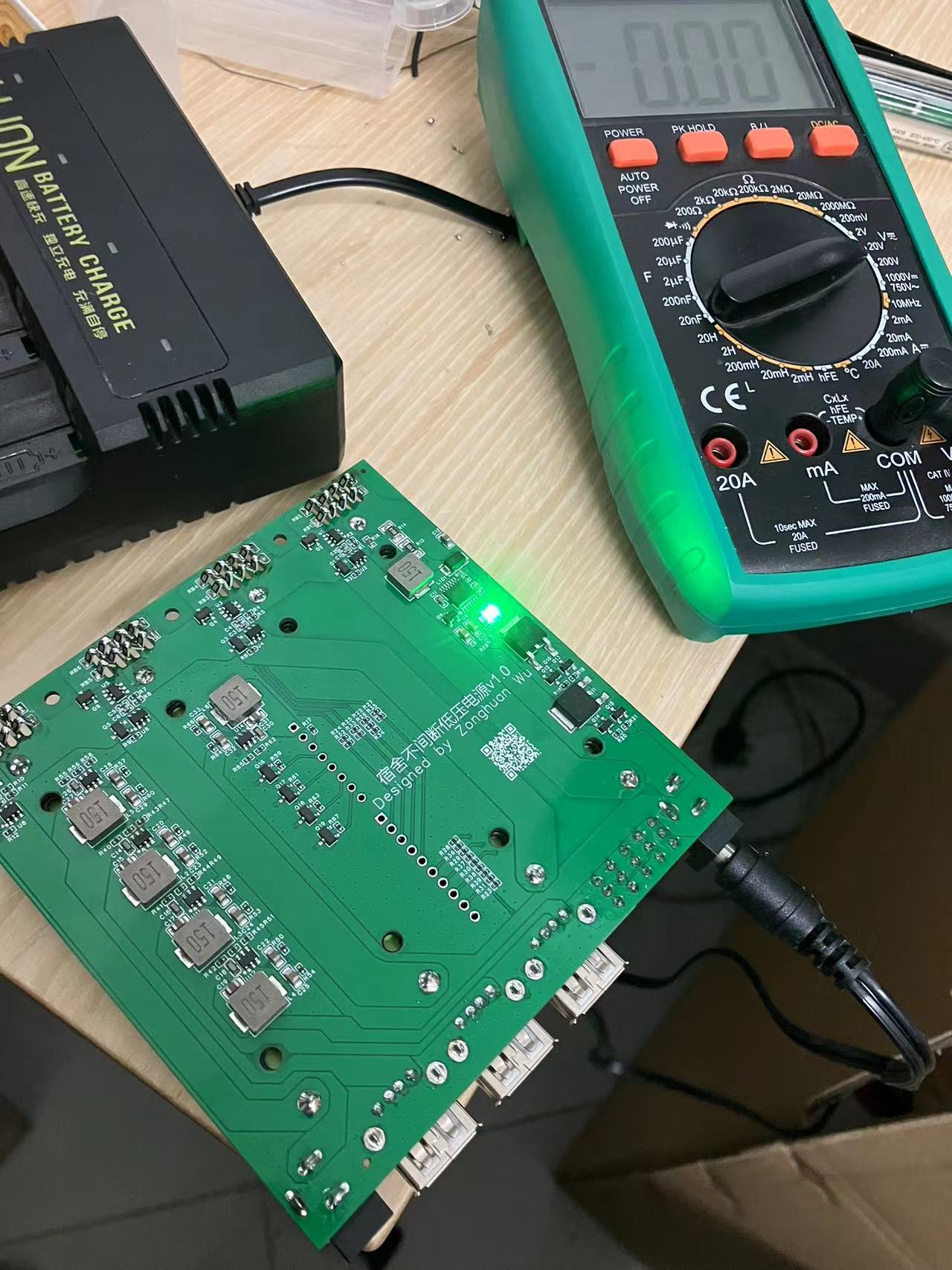
Below are some electrical parameters:
Input interface: DC power supply port 17V-26V (maximum 28V) (cannot charge below 17V, not recommended below 13V)
Output interface: 12V1A - DC power supply port (maximum 3A)
5V2A x 3 - USB-A (2.0 square port) (maximum 3A)
3.3V1A - header (maximum 3A)
Note that each power supply has a corresponding switch, which can be used to control the corresponding output interface. In particular, the 12V output only outputs when a plug is inserted.
Additionally, two sets of pin headers are provided between the two batteries in the middle, corresponding to the voltage divider feedback for each battery and the enable control of the power chip (excluding the 3.3V power supply). This means that users can design their own board, plug it in, and use a microcontroller to monitor the input and output voltages and control the 5V and 12V outputs (the microcontroller's enable/disable signal and the switch's enable/disable signal are ORed, meaning the microcontroller can only control output when the switch allows output; similarly, the switch can only control output when the microcontroller allows output (default is allowed).
Of course, this is only the first version, and it's working well for me so far. It hasn't exploded, outputs around 20W, doesn't get hot with a fan, and gets a little warm without a fan. The PCB design still has flaws; the output voltage is not very stable and doesn't reach the chip's 3A current limit.
I plan to change the input to Type-C and use the PD/QC protocol to get 20V, so I won't need an external 24V charger. I'm currently working on a plug-in board to collect data on the heat generation and key voltage changes of several critical chips. I'll also connect some external sensors to collect data on temperature, humidity, air pressure, TVOC, and eCO2, storing it on an SD card. (There's actually another fun feature, but I'll keep that a secret for now. If I can find the time to develop it in the future, I'll open-source it.)
This is my first open-source hardware project, and I'm not very good at formatting. Thank you to everyone in the open-source community who read this far! Please leave your valuable suggestions so we can learn from each other!


 京公网安备 11010802033920号

 IDT70V7288S15PFI


