 [2] The main controller is replaced with CW32F030C8T6. The minimum system circuit of MCU is added, and the reset button, BOOT selection interface, serial port download interface, and SWD debugging interface are brought out.
 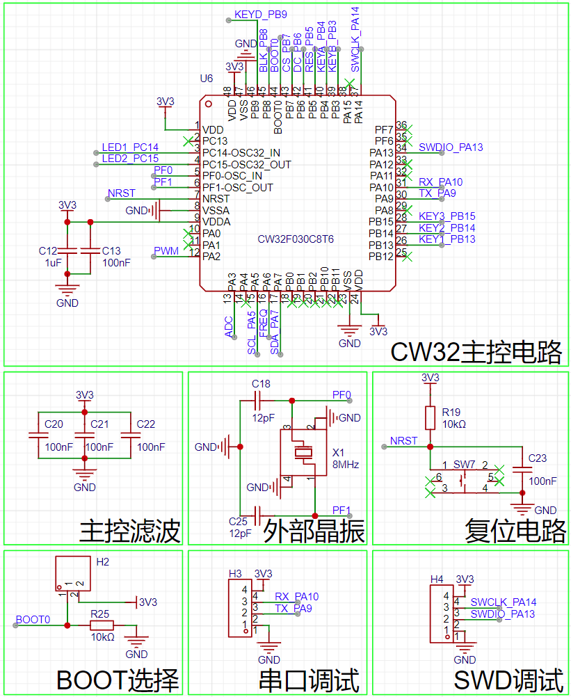 [3] The system power supply is provided by the PW5100-50 boost converter through USB/lithium battery to provide 5V, and 5V is output to AMS1117 to output 3.3V.
 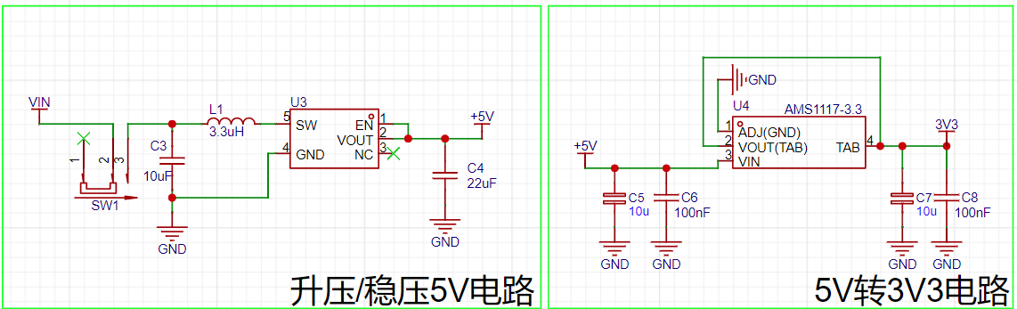 [4] To achieve a small size, the screen module recommended in the case was not used. Instead, a 1.8-inch TFT bare screen was adopted. The main control board integrates the driver peripheral circuit and is connected through a 14-pin ribbon cable socket.
 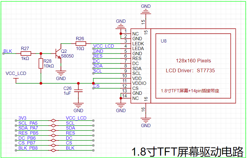 [5] The rest of the circuits are designed with reference to the official case.
  III. Physical Display
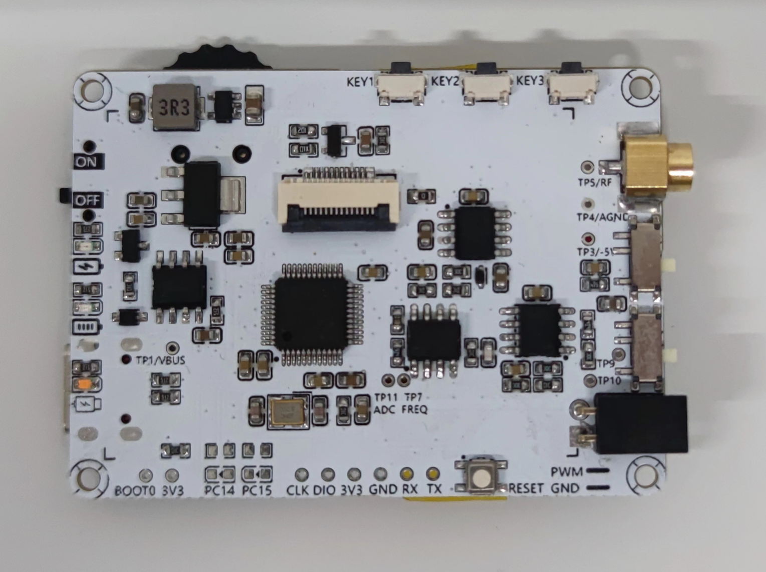
 [2] Assembled finished product
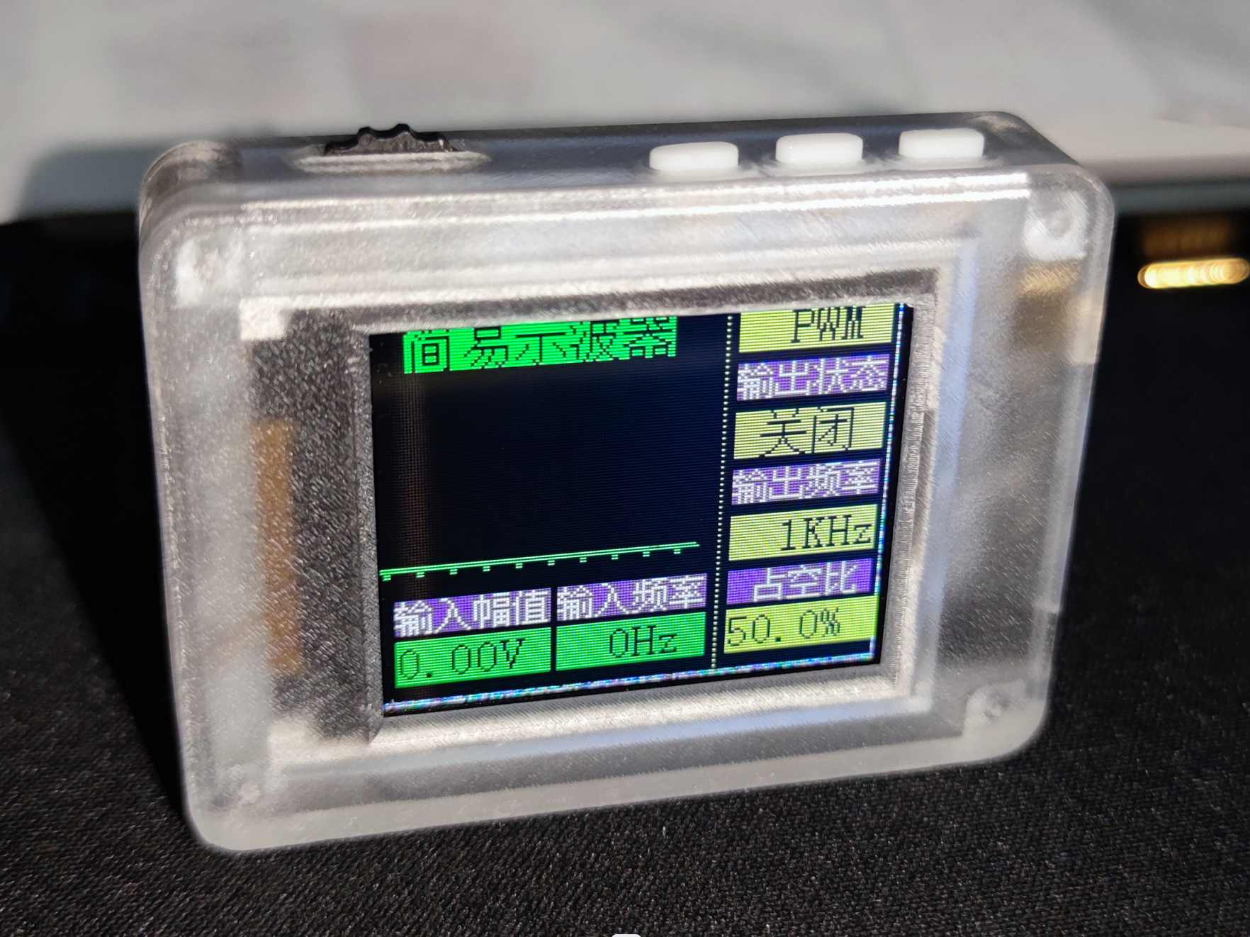

All reference designs on this site are sourced from major semiconductor manufacturers or collected online for learning and research. The copyright belongs to the semiconductor manufacturer or the original author. If you believe that the reference design of this site infringes upon your relevant rights and interests, please send us a rights notice. As a neutral platform service provider, we will take measures to delete the relevant content in accordance with relevant laws after receiving the relevant notice from the rights holder. Please send relevant notifications to email: bbs_service@eeworld.com.cn.
It is your responsibility to test the circuit yourself and determine its suitability for you. EEWorld will not be liable for direct, indirect, special, incidental, consequential or punitive damages arising from any cause or anything connected to any reference design used.
Supported by EEWorld Datasheet
EEWorld
subscription
account

EEWorld
service
account

Automotive
development
community

Robot
development
community

About Us Customer Service Contact Information Datasheet Sitemap LatestNews


Room 1530, 15th Floor, Building B,
No.18 Zhongguancun Street,
Haidian District,
Beijing, Postal Code: 100190
China
Telephone: 008610 8235 0740
 京公网安备 11010802033920号

 XC62RP3002PL


