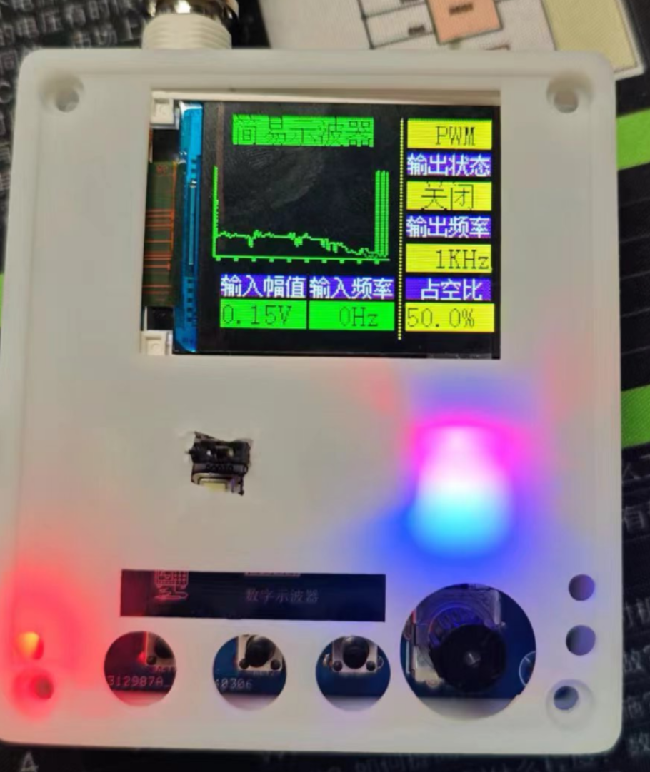
A Bilibili video
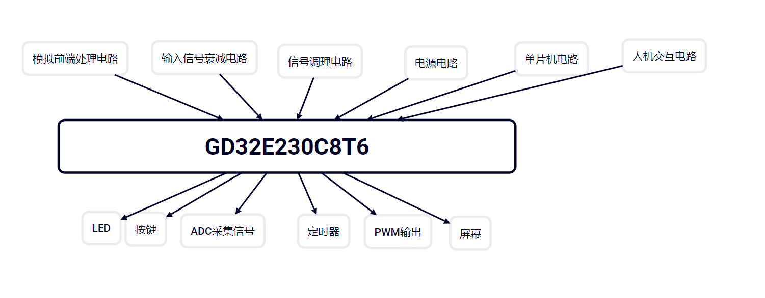
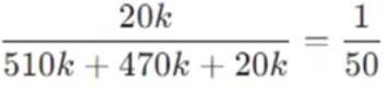
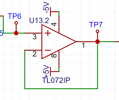
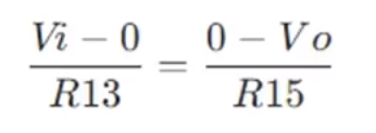
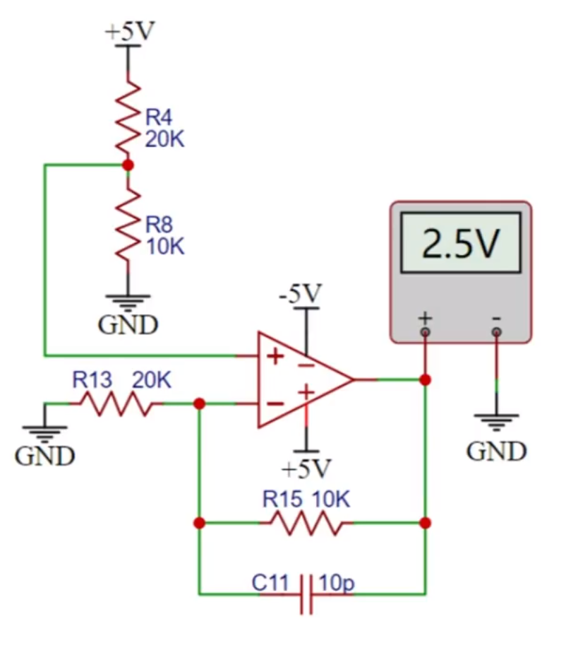
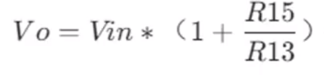
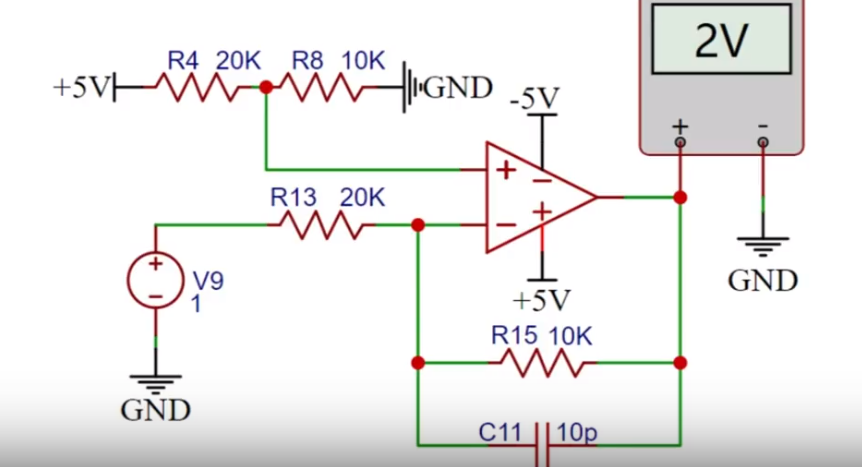
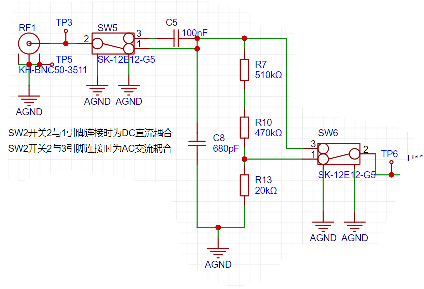
demonstrating a digital oscilloscope based on the GD32E230C8T6 (the video is too large and has been compressed; please extract video resources 1, 2, 3, 4, and 5 simultaneously if you need to download and extract it) . 【Digital Oscilloscope Based on GD32E230C8T6】 https://www.bilibili.com/video/BV1qJ4m177jP/?share_source=copy_web&vd_source=b56038c6fc5a32b35a0c1a44d8c245fc Circuit Principle : The analog front-end processing circuit is the most important part of the entire oscilloscope circuit design process. It extensively utilizes analog circuit knowledge, including input AC/DC coupling switching circuits, input signal attenuation circuits, and signal conditioning circuits. AC/DC coupling circuits can classify signal types into DC signals and AC signals. Real-world signals are often not ideal waveforms. For example, a DC power supply signal should be a horizontal DC signal, but it will always contain power supply ripple (AC signal). When acquiring AC signals, DC signals may also be mixed in, affecting the peak-to-peak value of the waveform. To ensure accurate measurement of the input AC signal, the characteristic of a capacitor to pass AC and block DC is utilized. By connecting a capacitor in series in the circuit, the DC component in the signal can be filtered out; this is the concept of AC coupling. DC coupling, on the other hand, does not perform any processing on the input signal. A toggle switch SW2 switches the input AC/DC coupling signal. When switch 2 is connected to 1, it is DC coupling; when switch 2 is connected to 3, it is AC coupling. How should the capacitor size be chosen? To solve this problem, it is necessary to understand the frequency characteristics of the capacitor. Ideally, the larger the DC blocking capacitor, the better. However, because different capacitance values have different self-resonant frequencies, below the self-resonant frequency, the capacitor exhibits capacitive behavior, and above that frequency, it exhibits inductive behavior. The larger the capacitor, the lower its self-resonant frequency; simply put, a large capacitor passes low frequencies, and a small capacitor passes high frequencies. As shown in the diagram, when the ceramic capacitor is 0.1uF (100nF), its self-resonant frequency is 4MHz. Generally, the cutoff frequency of the capacitor is required to be fc = 1/5 * fo, where fo is the operating frequency in the circuit. Therefore, 100nF is sufficient for this project. However, if the input signal frequency is higher, a smaller capacitor should be selected. After the signal passes through the AC/DC coupling selection circuit, switch SW3 selects two channels. When switches 2 and 3 are connected together, the input signal flows directly into the subsequent voltage follower circuit. When switches 2 and 1 are connected together, the input signal is attenuated to 1/50th of its original value after passing through a resistor divider network composed of resistors R7, R11, and R14. This indicates that when the input signal amplitude is small, the lower voltage range should be selected first. If the input signal amplitude is uncertain during measurement, the higher voltage range can be used first. If the measurement falls within the lower voltage range, the lower voltage range can be used to obtain a more accurate measurement result, while simultaneously protecting the circuit. The input signal attenuation circuit uses a BNC-to-alligator clip probe, a non-professional oscilloscope probe. Only a simple circuit analysis is provided; further details regarding probe selection and impedance are omitted. If using a passive probe from a professional oscilloscope, since the probe has a ×1 and ×10 range selection, accurate measurement results can be obtained by adjusting the compensation capacitor on the probe or C10 in the circuit when the range is ×10. C10 is generally an adjustable capacitor, and its actual size depends on the capacitance characteristics between different boards. The signal conditioning circuit includes a voltage follower and a signal amplification circuit composed of operational amplifiers. When analyzing this part of the circuit, it is necessary to understand the principles of virtual open and virtual short of operational amplifiers. Virtual open: The input impedance of an ideal operational amplifier is infinite, but the input impedance of a real operational amplifier is finite. If a voltage is applied to the input terminal of the operational amplifier and the current is measured, the current reading will be close to 0, giving the impression that the operational amplifier is internally disconnected and no current is flowing in. However, it is actually connected; this phenomenon is called virtual open. This can also be understood using Ohm's Law, U=I*R. When the voltage is constant, the current is inversely proportional to the resistance; if the resistance is infinitely large, the current becomes infinitely small, approaching zero. Virtual Short: A virtual short phenomenon occurs when an op-amp is in deep negative feedback, making the potentials at the two input terminals equal, as if the two input terminals were shorted together. This can be approximated as v+=v-. In negative feedback, a portion of the op-amp's output signal is extracted and fed back to the input terminals. This feedback makes the voltage difference between the two input terminals (positive and negative) approach zero; the voltages at the two input terminals are almost equal. Although the two input terminals of the op-amp are not electrically directly short-circuited, due to the negative feedback, the voltages at the two input terminals are almost equal, as if they were short-circuited, hence the term virtual short. Voltage Follower : A voltage follower is characterized by its output voltage amplitude and polarity being the same as the input voltage. It also has high input impedance and low output impedance, and is often used as a buffer stage and isolation stage. Due to the virtual short characteristic of the operational amplifier, V+=v-. Since Vin=V+ and Vout=V-, Vin=Vout, meaning the voltage at test point TP6 is the same as the voltage at TP7. The input signal to the inverting amplifier is input from the inverting input terminal of the operational amplifier, giving it the function of outputting signals with opposite polarity and amplifying the input signal. When the non-inverting input terminal of the operational amplifier is grounded, IJ+=OO, thus forming an inverting amplifier circuit. Due to the virtual short characteristic of the operational amplifier, the current flowing into the operational amplifier from the inverting input pin is 0. R13 and R15 can be considered as connected in series, so the current flowing through them is the same. Due to the virtual short characteristic, v+=v-=0 and i+=i-=0. Therefore, the formula for calculating the inverting amplifier is: Substituting Vi=1V, R13=20K, and R15=10K into the series circuit, we get Vo=-0.5V . Since the currents in the series circuit are equal, the output voltage is -0.5 volts. The input signal of the non-inverting proportional amplifier is input from the non-inverting input terminal of the operational amplifier, and it has the function of outputting the same polarity and amplifying the input signal. When the inverting input terminal of the operational amplifier is grounded, U-=0. At this time, a non-inverting proportional amplifier circuit is formed. Due to the virtual open characteristic of the operational amplifier, the current flowing through the two input pins of the operational amplifier is 0, that is, the current flowing through R4 is 0, Vin=V+. It can be regarded as R13 and R15 connected in series, so the current flowing through them is also the same. Due to the virtual short characteristic, the voltages of the two input pins are the same, that is, V+=V-, so Vin=V+=V-. Vo forms a loop with R13 and R15, so the current flowing through it is... Considering R13 alone, the current flowing through it is also equal to the voltage across it divided by its resistance value. Substituting into Vin=V+=V-, we get the following formula: From this, we can derive that substituting Vin=5/3V, R3=20K, and R5=10K, we get Vo=2.5V. The non-inverting proportional amplifier circuit is verified to be correct, and the output voltage is 2.5 volts. Synthetic Circuit: The inverting and non-inverting proportional amplifier circuits are analyzed together: When the non-inverting input of the op-amp is grounded, U+=0, substituting R15=10K, R13=20K, V1=-0.5Vi. When the inverting input of the op-amp is grounded, U-=0,


Substituting R15=10K, R13=20K, Vin=5/3V, V2=2.5V.
When both circuits work together, vout=V2+V1=2.5+0.5Vin. Simplifying, we get:
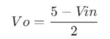
The Vo signal will be directly connected to the microcontroller's ADC pin. Since the microcontroller acquires the ADC voltage range of 0, 3, and 3V, the oscilloscope's input voltage range can be calculated.
When the input signal Vin does not attenuate, substituting Vo=0 and vo=3.3V into the formula yields:

When the input signal Vin attenuates by 1/50, substituting Vo=0 and Vo=3.3V into the formula yields:

We obtain the following conclusion
: When switches 5 and 3 are connected together, the measurable input signal amplitude is -1.6 to 5V
. When switches 2 and 1 of SW5 are connected together, the measurable input signal amplitude is 80V-250V.
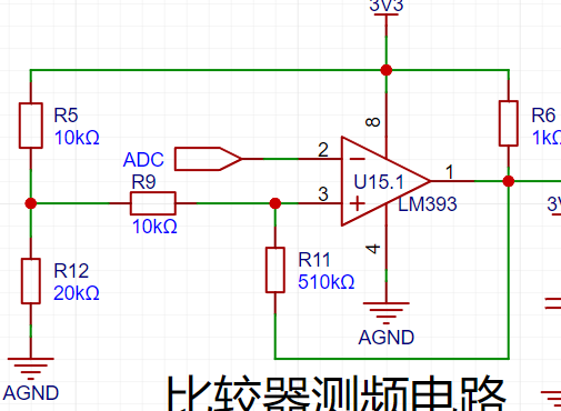
The comparator frequency measurement circuit,
to achieve frequency detection, compares the ADc input signal with a hysteresis comparator to realize the frequency measurement function. The hysteresis comparator is a type of voltage comparator. A conventional voltage comparator is a single-threshold comparator, with only one threshold voltage in the circuit. However, even a small change in the input voltage near the threshold will cause a significant change in the output voltage.
To enhance the circuit's anti-interference capability, positive feedback is introduced on the basis of the single-threshold comparator, ensuring signal stability within a certain range. After passing through the hysteresis comparator circuit, a square wave signal is output. The period of the input waveform is calculated using the microcontroller's timer capture function.

The threshold voltage of the hysteresis comparator circuit needs to be analyzed separately based on the op-amp output result. The original circuit is shown in the figure below:
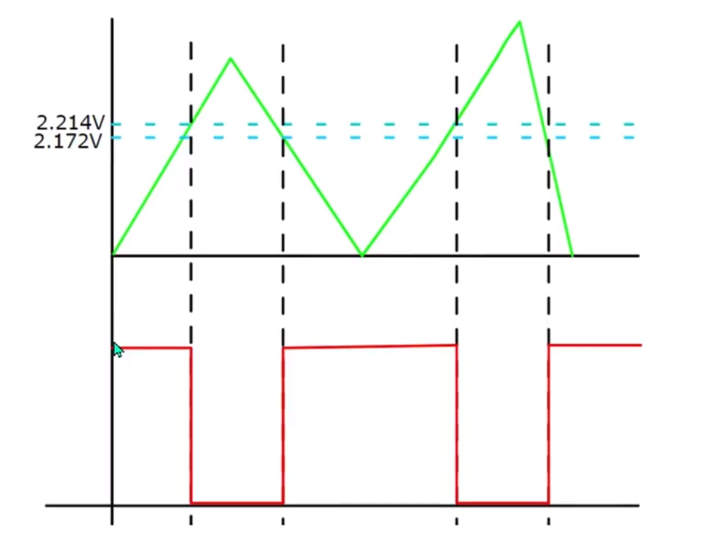
When the output is high, the output terminal is pulled up to a high level. The equivalent circuit is shown in the middle figure below, and Uth = U+ = 2.214V is calculated.
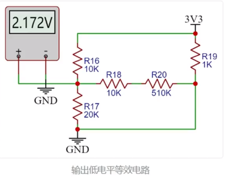
When the op-amp output is low, the output terminal is grounded. The equivalent circuit is shown in the diagram on the right below, and we can calculate Utl = U- = 2.172V.

The green line in the diagram below represents the signal input voltage change. Starting from 0 potential, the initial output state is high. When the input voltage reaches 2,214V,
the output signal becomes low, until the input signal falls below the lower threshold of 2,172V, at which point the output becomes high again. The threshold for the next change level can be determined based on the current output
state . When the output is high, the high threshold Uth is used; when the output is low, the low threshold Tt is used.
The reason for setting the thresholds close together is to avoid misinterpretation caused by signal interference.
The green line in the diagram below represents the signal input voltage change. Starting from 0 potential, the initial output state is high. When the input voltage reaches 2,214V, the output signal becomes low, until the input signal falls below the lower threshold of 2.172V, at which point the output becomes high again. The threshold for the next level change can be determined based on the current output state of the comparator. A high threshold (Uth) is used when the output is high, and a low threshold (Ttl) is used when the output is low. The thresholds are set close to each other to avoid misidentification caused by signal interference.
Note:
The positive input signal of the threshold comparator op-amp is a fixed level. If using a microcontroller with a DAC output, the potential at this point can be freely configured to change the DC voltage and set the trigger mode.
Power Circuit
USB Power Input:
This project uses the GD32 minimum system board as its core, with an onboard 5V to 33V step-down circuit. Therefore, only a 5V power input circuit needs to be designed when designing the expansion board. The mainstream Type-C interface is chosen here. This interface has only two wires and is plug-in packaged, making it convenient for beginners to learn soldering. However, it should be noted that this Type-C interface is only for power supply and cannot transmit data. If data transmission is required, the Type-C interface on the core board can be used. SW1 is the main power switch, C1 is the input filter capacitor, and RI is the current-limiting resistor for LED1. In addition to the power input circuit,

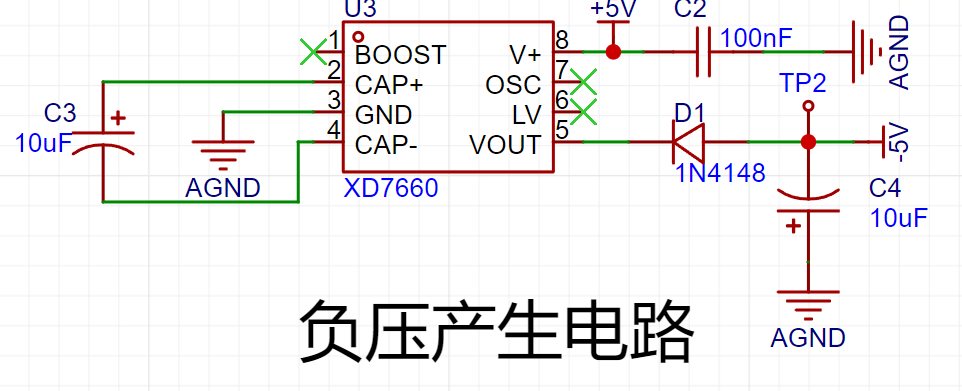
the negative voltage
generation circuit uses an XD7660 negative voltage generator to ensure the operational amplifier's performance in measuring negative voltages. This chip has a simple external circuit, requiring only two capacitors and a diode to operate. Theoretically, it can output a 5V voltage when the input voltage is +5V. However, due to the chip's internal voltage drop and conversion efficiency, the actual measured negative voltage is around 3V, which still meets the operational amplifier's requirements.
For the microcontroller circuit
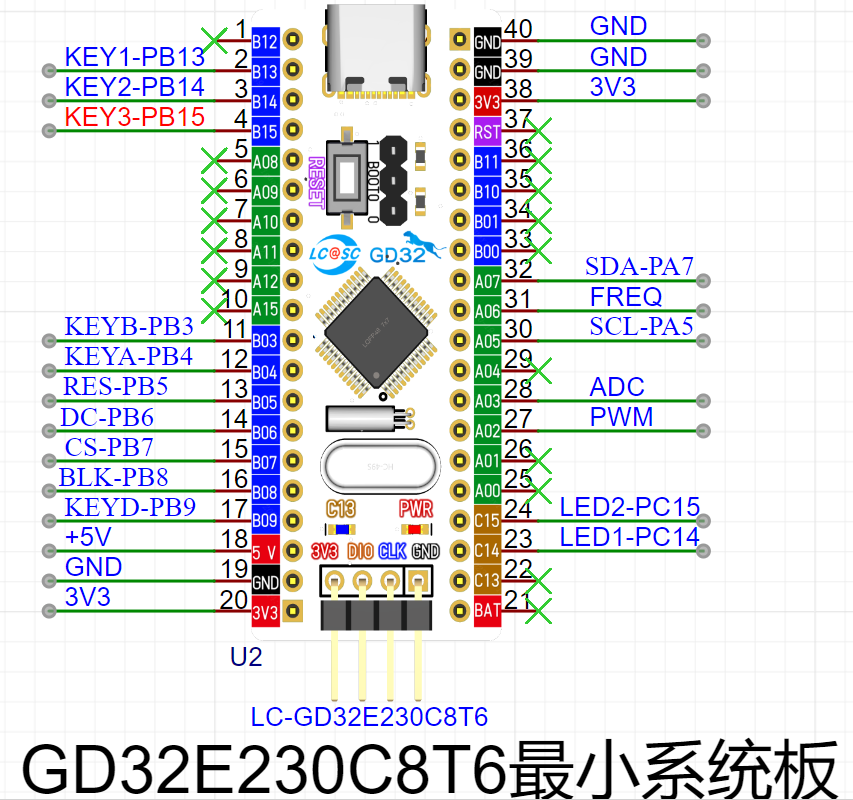
, this project uses the GD32 minimum system board from the LCSC development board team as the main controller. This development board is a domestically produced board jointly developed by the LCSC team and GigaDevice. It features an onboard CH340 download chip, requiring only one data cable for programming and serial port debugging. It is also compatible with the size and pin configuration of the STM32 minimum system board and can be directly replaced.
The human-computer interaction circuit
LCD display circuit
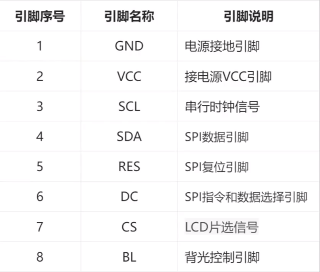
1.8TFT is a color display screen with 128×160 color pixels. It uses a four-wire SPI communication method to connect with the microcontroller. It has a total of eight pins. The module pin description and connection with the microcontroller are as follows:
Screen purchase link:
https://item.taobao.com/item.htm?_u=n34jmok8fa2c&id=709270273013&spm=a1z09.2.0.0.67002e8dxYMtHQ
High-definition SPI TFT color display screen 0.96-inch 1.3-inch 1.44-inch 1.8-inch OLED LCD screen st7735 - Taobao (taobao.com)

Rotary encoder circuit The rotary encoder
is a special kind of button. The ECII rotary encoder used in this project has five pins. Among them, the DE pins are similar to ordinary button pins. They are connected when pressed and disconnected when released. The remaining ABC pins are used to detect the rotation direction of the knob. The C pin is the common terminal and can be directly grounded.
In the rotary encoder, there is a phase difference between signal pins A and B. This means that a change in the signal on one pin precedes a change on the other, meaning the two pins do not change simultaneously. By detecting which pin changes first, the system can determine whether it's rotating in the forward or reverse direction.

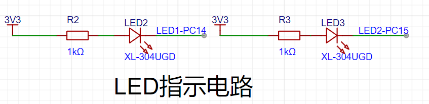
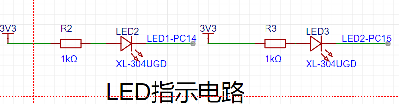
The LED indicator
circuit is relatively simple, using a low-level drive. When the microcontroller pin outputs a low level, a potential difference exists across the LED, and the LED lights up; when the microcontroller pin outputs a high level, the LED turns off. In addition to the rotary
encoder
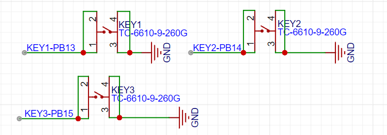
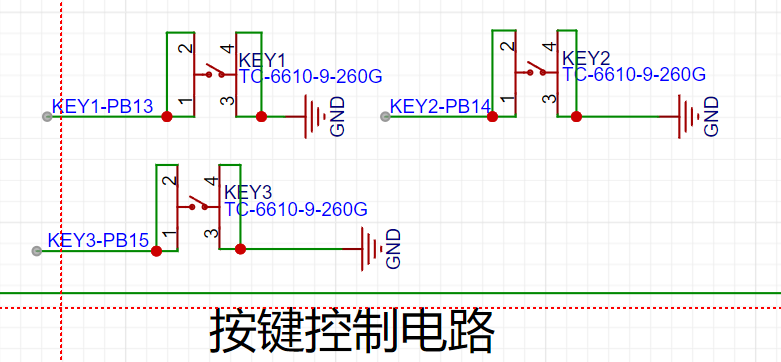
, the project uses three independent buttons to control the system. One side of each button is directly grounded, and the other side is connected to a microcontroller pin. When the microcontroller pin detects a button press, it connects directly to GND (Ground). The microcontroller receives this grounding signal and then executes the corresponding function. To save hardware costs, debouncing can be incorporated into the software design to prevent accidental triggering due to mechanical button vibration. In addition to the oscilloscope detection function,
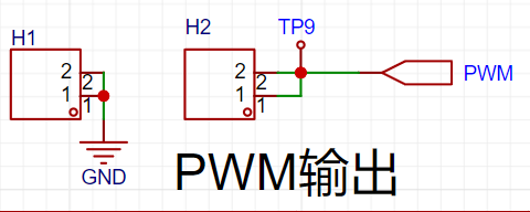
the waveform output interface
also features a dedicated PWM signal for simulating a simple function generator. This allows for the output of a simple square wave signal by changing the PWM frequency and duty cycle.
PCB
trace lengths should be kept as short as possible, and traces should extend along the pad direction.
Sharp angles and right angles should be avoided in the PCB design to prevent unnecessary radiated interference.
During the routing process, one end of the trace should not be floating to avoid the antenna effect.
When routing power supply filters and decoupling capacitors, ensure that the current flows through the capacitor filter before supplying power to the device.
When designing the traces, ensure that the loop area of the signal is as small as possible, i.e., the minimum loop principle. When routing PCB traces, try to widen the width of power and ground lines, with ground line > power line > signal line width
. Traces should be mainly straight, and if a bend is necessary, the corner should be 135 degrees. Prioritize obtuse or rounded corners to minimize the use of right angles.
Power traces should be wider than signal traces. In this project, signal traces are 15mil wide, and power traces are 20mil wide. GND and AGND networks are connected using copper pours. It
is recommended to prioritize top-layer routing. If a route is blocked, use vias to establish a connection between the top and bottom layers, then continue routing to the bottom layer. Similarly, if a route is blocked on the bottom layer, use vias to
connect to the top layer. AGND and GND should be copper-poured separately at the 0-ohm resistance point. The copper pour range needs to be adjusted based on the PCB layout.
If flying wires remain after copper pouring, they can be eliminated by placing vias of the corresponding network at the location of the flying wire, adjusting the trace position to allow network connection, or manually connecting the wires.
After routing, teardrops can be added in the "Tools" menu to strengthen the connection between the pads and traces. Finally, perform copper pouring. If the traces have been moved or adjusted, use the shortcut Shift+B to rebuild the copper pour. LED Lighting Principle:
An LED contains a semiconductor chip, half of which is a P- type semiconductor and the other half is an N-type semiconductor. When these two semiconductors are connected, a P-N junction is formed. When current flows through the wire and acts on this chip, electrons are pushed into the P region. In the P region, electrons recombine with holes, and energy is emitted in the form of light. This is the principle behind LED light emission. The LED driver principle , or making an LED light up, involves first examining the schematic diagram to see the connection relationships of the LED pins. High and low levels can be output through the corresponding microcontroller pins, thereby changing the potential difference across the LED to form a current loop and light the LED. The `Init_LED_GPIO` function on the oscilloscope board is used to initialize the GPIO pins connected to the LED. First, it enables the GPIOC clock. Then, it sets two GPIOC pins (PIN_14 and PIN_15) to output mode without enabling pull-up or pull-down resistors. Next, it sets the output type of these two pins to push-pull output and the output speed to 50MHz. Finally, it calls the `CLose_LED` function to turn off the LED (i.e., the LED is off during initialization). The ` Open_LED` function is used to turn on the LED. The `CLose_LED` function takes one parameter, `value`, which determines which LED is turned on. If `value` is 1, the GPIOC pin PIN_14 is pulled low, which typically means the LED connected to that pin will light up. If `value` is 2, the GPIOC pin PIN_15 is pulled low, which typically means another LED connected to that pin will light up. If `value` is neither 1 nor 2, no action is taken. The `CLose_LED` function turns off LEDs. It also takes one parameter, `value`, which determines which LED is turned off. If `value` is 1, the GPIOC pin PIN_14 is set high, which typically means the LED connected to that pin will turn off. If `value` is 2, the GPIOC pin PIN_15 is set high, which typically means another LED connected to that pin will turn off. If `value` is neither 1 nor 2, no action is taken. The independent button structure consists of four contacts: left, right, and 12. These contacts are essentially non-locking tactile switches. When pressed, they close; when released, they open. The 12 and 34 contacts are internally connected. The microcontroller determines button press status by detecting high and low voltage changes before and after the button is pressed. Different functions and settings can be implemented through program control. Mechanical buttons, due to mechanical elasticity, typically experience a period of contact bounce when pressed or released before stabilizing. The bounce duration depends on the switch's mechanical characteristics, generally 5-10ms. Detecting button press during this bounce can lead to errors. To overcome this bounce, debouncing measures are necessary, including hardware and software debouncing. Hardware debouncing typically involves adding capacitors and resistors to the button detection pins, using an RC delay circuit to absorb and filter out high-frequency oscillations during button press. Software debouncing generally uses a delay. When a button press is detected, the voltage level is not immediately checked. Instead, a short delay is made before checking the current pin's voltage level. This eliminates interference during the bounce process, which is typically less than 10ms. Driving Principle: Driving an independent button first requires determining the pins at both ends of the button. Depending on the pin connections on both sides, there are two cases: If the button side is connected to power , the GPIO needs to be set to pull-down (default low). The button press is determined by checking if the corresponding GPIO pin is high. If the button side is connected to GND, the GPIO needs to be set to pull-up (default high). The button press is determined by checking if the corresponding GPIO pin is low. GPIO Initialization: The `Init_Key_GPIO` and `Init_EC11_GPIO` functions initialize the GPIO pins connected to the button. They achieve this by configuring the GPIO mode (input mode, pull-up resistor), enabling interrupt lines, and initializing interrupt lines. `rcu_periph_clock_enable`: Enables the clock of a specific peripheral so that it can function. `gpio_mode_set`: Sets the GPIO pin mode; here it's input mode, and pull-up resistors are used. `nvic_irq_enable`: Enables interrupts so that an interrupt can be triggered when the state of the GPIO pin changes. `syscfg_exti_line_config`: Configures the external interrupt line, connecting the GPIO pin to the interrupt line. `exti_init`: Initializes the external interrupt line, setting the trigger mode (falling edge or rising edge trigger). `exti_interrupt_flag_clear`: Clears the interrupt flag, ensuring there are no unhandled interrupts.
The key handling function
`Key_Handle` adjusts the `pwmOut` member of the `Oscilloscope_Value` structure based on the key press value.
A `switch` statement performs different operations based on the key press value.
`KEY1` and `KEY2` increment and decrement the value of `pwmOut` respectively, checking if it is out of range.
`KEY3` and `KEY4` appear to perform a delay operation, but they do not actually change the value of `pwmOut`. This could be an error or an incomplete part of the code. The
interrupt service routine
`EXTI4_15_IRQHandler` is an interrupt handler that is automatically called when any of the external interrupt lines 4 through 15 triggers an interrupt.
The function first checks which interrupt line triggered the interrupt using the `exti_interrupt_flag_get` function. This is done by checking the interrupt flags of `EXTI_9`, `EXTI_13`, `EXTI_14`, `EXTI_15`, and `EXTI_4`.
If an interrupt is detected, it clears the corresponding interrupt flag to avoid handling the same interrupt repeatedly.
Based on the pin that triggered the interrupt, the function sets `keyValue` to the corresponding button value (such as KEY1, KEY2, KEY3, KEY4, or EC11_KEY).
If `keyValue` is not 0, it means a button was indeed pressed, so the `keyValue` member of the `Oscilloscope_Value` structure is set to this button value, and the `Key_Handle` function is called to handle the button event.
The `Key_Handle`
function adjusts the `pwmOut` member of the `Oscilloscope_Value` structure according to the button value. This is typically used to control the duty cycle of the PWM (Pulse Width Modulation) signal.
For KEY1, it increases the value of `pwmOut`, but not exceeding `timerPeriod`. This is likely used to increase the duty cycle of the PWM signal, thereby increasing the strength or duration of the output signal.
For KEY2, it decreases the value of `pwmOut`, but not less than 0. This is used to decrease the duty cycle of the PWM signal.
The processing logic for KEY3 and KEY4 looks somewhat strange because they perform a delay operation but do not change the value of `pwmOut`. This could be a code error, or these buttons were originally intended for other functions that have not yet been implemented. The `Init_USART` function initializes the USART (Universal Synchronous Asynchronous Receiver/Transmitter)
serial port, enabling it to send and receive data. Function parameters: `bound` is the baud rate, which is the number of symbols transmitted per second and determines the communication rate. Functionality: Enables the clock for the GPIOA port and USART0. Configures pins 9 and 10 of the GPIOA port for multiplexing, typically used for USART's TX and RX. Sets the mode of pins 9 and 10 to multiplexed (AF) and enables the pull-up resistors. Configures the parameters for USART0, including data bit width (8 bits), stop bits (1 bit), parity (none), and baud rate. Enables the receive and transmit functions of USART0. Finally, enables USART0. The `fputc` function is a redirected implementation of the standard library function `fputc`, used to send characters to the serial port. Function parameters: `ch` is the character to be sent, and `f` is a file pointer (which may not be used in this context). Functionality: Uses the `usart_data_transmit` function to send the character `ch` to USART0. A while loop is used to wait until the USART0 transmit buffer is empty (the USART_FLAG_TBE flag is set) to ensure that the character is successfully sent. The sent character 'ch' is then returned. Interrupt Introduction: An interrupt is a situation where, while the microcontroller is executing the current program sequentially, a situation requiring urgent handling occurs. The microcontroller pauses the currently executing program and performs the urgent task. After the task is completed, the microcontroller automatically returns to the previously paused program. This interruption due to external factors is called an interrupt. Interrupt Application : Normal programs execute sequentially, but in embedded systems, brief events requiring urgent handling often occur, such as button presses. While infinite loop detection can also work, it consumes a lot of CPU resources for useless detection. Interrupts save resources by only handling the button press event when it occurs. External Interrupts: The GD32E230 external interrupt (EXTI) includes 21 independent edge detection circuits and can generate interrupt requests or wake-up events to the processor core. EXTI has three trigger types: rising edge trigger, falling edge trigger, and arbitrary edge trigger. Each edge detection circuit in EXTI can be configured and masked independently. Interrupt Triggering: The external interrupt EXTI trigger source of GD32E230 includes 16 lines from I/O pins and 5 lines from internal modules. By configuring the SYSCFGEXTISS× register, all GPIO pins can be selected as EXTI trigger interrupt priorities: GD32E230 is an M23 core and does not have the concept of interrupt priority grouping. It supports 4 priority settings (3). The smaller the number, the higher the level. High priority interrupts can preempt low priority interrupts. Rotary Encoder Principle Explanation : A rotary encoder can be regarded as a displacement sensor. By rotating it, it can be determined whether it is rotating forward or backward, and the angle of rotation. As can be seen from the symbol, the DE pin is a normal switch. When the rotary encoder is pressed, the switch is turned on, and when it is not pressed, the switch is turned off. Rotation judgment is mainly made through the three pins ABC. Port C is connected to GND, and pins A and B are connected to GPIO. The software pull-up is used. When rotating forward, the internal contacts will first contact A and then contact B. When rotating backward, the opposite is true. Therefore, to determine whether the rotation is clockwise or counterclockwise, one pin can be designated, and the level of another pin can be checked at its falling edge. For example, when detecting port A, if port B is high when triggered by the falling edge of port A, it's clockwise; if it's low, it's counterclockwise. ADC Signal Acquisition Introduction: An ADC is an analog-to-digital converter used to convert analog signals into digital signals. We know that analog signals are continuous, and their values can vary arbitrarily within a certain range. Digital signals, on the other hand, are discrete and can only take a finite number of values. The working principle of an ADC is to convert the analog signal into a discrete digital signal through sampling, and then process it through quantization, encoding, etc., to finally obtain the corresponding digital representation. The higher the sampling frequency of the ADC, the closer the obtained digital signal is to the original analog signal, that is, the higher the fidelity, but it requires more resources and computational power.
The GD32E230 integrates a 12-bit successive approximation ADC, capable of sampling analog signals from 10 external channels and 2 internal channels, with a maximum sampling rate of 2 MSPS.
The GD32E230 ADC supports three modes: scan mode, automatic channel conversion mode, and continuous mode.
In scan mode, the ADC scans multiple channels in a preset order, sampling and converting each channel once. DMA must be enabled in scan mode because without DMA, channel data may be overwritten by data from the next channel.
In automatic channel conversion mode, similar to an interrupt, when an injected channel is triggered, that channel is sampled and converted first.
In continuous mode, once the ADC is started, it continuously samples and converts the selected channels until a function command stops it; conversion in continuous conversion mode does not require restarting.
Note that these modes are not a one-to-many structure, but rather a multi-select, freely combinable structure. For example, continuous scan conversion mode allows for continuous, uninterrupted scanning.
If all three modes are disabled, single conversion mode is enabled.
The GD32E230 ADC supports various data alignment methods to adapt to different application scenarios. Common data alignment methods include left alignment and right alignment. In right alignment mode, the ADC data is right-aligned to the least significant bit after conversion, and any missing bits are filled with 0s in the higher bits.
Left alignment aligns to the most significant bit and fills the lower bits with 0s.
Generally, right alignment is chosen so that the converted data can be directly used for calculation.
The steps of ADC conversion are: sampling, holding, quantization, and encoding. The faster the conversion time is set, the lower the sampling accuracy. Furthermore, with a faster conversion time, the external impedance also needs to be lower to reduce interference.
The GD32E230 ADC resolution can be configured to 6, 8, 10, and 12 bits. If high accuracy is not required, a faster conversion time can be obtained by reducing the resolution.
To use the ADC function, the ADC clock needs to be enabled. The ADC clock differs from other external clocks; it has a maximum clock frequency of 28MHz.
The ADC clock source is the AHB (72MHz-max), APB2 (72MHz-max), or lRC28 (28MHz) bus. A clock source needs to be selected and divided to below 28MHz. Assuming the AHB bus is used with a 3-divider, the input clock is 72/3 = 24MHz, close to the maximum speed.
The `get_ADC_Value` function
retrieves the ADC value stored in the `adc_value` array. It accepts an index `value` as a parameter and returns the ADC value at that index. If the index exceeds the array range (i.e., greater than `ADC_VALUE_NUM`), the function resets the index to 0. After returning the ADC value, it also clears the value at the corresponding position in the array.
The `Init_ADC`
function initializes the ADC module. It first enables the relevant GPIO pins and the ADC module clock. Then, it configures the ADC clock, pin mode, special functions (such as continuous mode, scan mode, and injection group auto-switching mode), data calibration, channel length, general channel configuration, and trigger source. Then, it enables the ADC and initiates calibration. Finally, it enables DMA mode and starts the ADC via software trigger.
The `ADC_DMA_Init` function
enables the DMA clock: `rcu_periph_clock_enable(RCU_DMA);` ensures the DMA controller clock is enabled so that DMA can function correctly.
The DMA parameter structure defines a variable of type `dma_parameter_struct` called `dma_data_parameter` to store the DMA configuration parameters.
Enabling DMA interrupts: `nvic_irq_enable(DMA_Channel0_IRQn, 0U);` enables interrupts for DMA channel 0 so that it can respond to interrupts when a DMA transfer is complete.
Resetting channel 0: `dma_deinit(DMA_CH0);` resets DMA channel 0 to its initial state.
DMA parameter configuration:
`periph_addr`: the base address of the peripheral (ADC), set to the address of `ADC_RDATA`.
`periph_inc`: the peripheral address does not increment because ADC data is read continuously from the same address.
`memory_addr`: Memory address, set to the address of the `adc_value` array.
`memory_inc`: Memory address increments, as data is continuously written to different locations in the `adc_value` array.
`periph_width` and `memory_width`: Both set to 16 bits, because both ADC data and array elements are 16 bits wide.
`direction`: Data transfer from the peripheral (ADC) to memory.
`number`: The amount of data transferred, set to `ADC_VALUE_NUM`, i.e., the array size.
`priority`: Sets the high priority of the DMA transfer.
DMA Channel 0 Initialization: `dma_init(DMA_CH0, &dma_data_parameter);` Initializes DMA channel 0 using the configured parameters.
DMA Circulation Mode Enable: `dma_circulation_enable(DMA_CH0);` Enables DMA circulation mode, meaning that after a DMA transfer completes, it automatically restarts, continuously reading data from the ADC into memory.
DMA Channel 0 Enable: `dma_channel_enable(DMA_CH0);` Starts the transfer on DMA channel 0.
Enable DMA transfer completion interrupt: `dma_interrupt_enable(DMA_CH0, DMA_CHXCTL_FTFIE);` An interrupt is generated when DMA completes a data transfer.
`DMA_Channel0_IRQHandler` interrupt handler
interrupt flag check: `if(dma_interrupt_flag_get(DMA_CH0, DMA_INT_FLAG_FTF))` Checks if DMA channel 0 has completed a data transfer.
Interrupt handling:
`oscilloscope.showbit=1;` Sets the `showbit` field of the `oscilloscope` structure to 1, possibly to notify other programs that a partial DMA transfer has completed and the data is available for display or processing.
`dma_channel_disable(DMA_CH0);` Disables DMA channel 0, stopping further DMA transfers. This is typically used to prevent new data from being written to the `adc_value` array after processing the current batch of data until the program is ready to restart DMA.
Clear the interrupt flag: `dma_interrupt_flag_clear(DMA_CH0, DMA_INT_FLAG_G);` This clears the DMA interrupt flag, ensuring that interrupts will not be triggered accidentally again.
Timer
Timers are integrated within a microcontroller and can be controlled programmatically. The timing function of a microcontroller is implemented through counting. Each clock cycle generates a pulse, and the counter increments by 1. When the count reaches the set value, the time has elapsed.
As a fundamental microcontroller component, timers are used in almost every program. For example, millisecond (ms) and microsecond (µs) delays are achieved by counting using the system tick timer. In addition, timers can be used for PWM output, input capture, and encoder modes, among others.
The GD32E230 timer supports three counting modes:
Up Counting Mode: The counter counts from 0 to the auto-reload value (cycle value), then restarts counting from 0 and generates a counter overflow event.
Down Counting Mode: The counter counts down from the auto-reload value (cycle value) to 0, then restarts counting from the auto-reload value and generates an overflow event.
Center-Aligned Mode: The counter counts from 0 to the auto-reload value -1, generates a counter overflow event, counts down to 1 and generates another counter overflow event, then restarts counting from 0.
PWM Output
Introduction
PWM (Pulse Width Modulation) is an abbreviation for Pulse Width Modulation. Pulse Width Modulation is a highly effective technique that uses the digital output of a microprocessor to control analog circuits. By modulating the width of a series of pulses, the desired waveform (including shape and amplitude) is obtained. That is, by changing the time occupied by the high level within a cycle, i.e., the duty cycle, the voltage is adjusted.
PWM has wide applications in various fields
. In lighting control:
the brightness . In motor control: the speed and torque of the motor are controlled by adjusting the duty cycle of the PWM signal.
GD32 PWM Introduction:
Each PWM channel corresponds to a pin of the microcontroller. This pin is not unique and fixed;
one or more pins may correspond to the same channel. For example, MER14CHO corresponds to PA2 and PB14,
meaning that both PA2 and PB14 pins can be configured as timer channel 0. We can
choose .
PWM Basic Parameters:
Frequency:
The number of times the signal goes from high to low and back to high within a unit of time (s) (period).
Unit: Hz, kHz, MHz
. Frequency = 1/period;
assuming a frequency of 50Hz, one period means 20ms (1/20ms) * 1000 = 50Hz.
Duty Cycle:
The proportion of time the signal is at a high level within one pulse period.
Unit: %
The `Init_PWM_Output` function initializes the PWM output. It accepts two parameters: period and pulse. Inside the function, it first configures pin 2 of GPIOA for multiplexing and sets it to push-pull output mode. Then, it enables the clock, initializes the timer parameter structure, configures the timer channel output parameter structure, sets the output compare value, configures the output mode, etc. Finally, it disables the timer. The `Set_Output_PWMComparex` function sets
the PWM duty cycle. It accepts one parameter, `value`, representing the duty cycle value. Inside the function, it calls the `timer_channel_output_pulse_value_config` function to set the pulse value of timer channel 0.
The `Set_Output_Freq` function is used to set the frequency of the PWM output. It accepts a parameter `value`, representing the frequency value. Internally, the `timer_autoreload_value_config` function is called to set the timer's auto-reload value.
Input capture frequency measurement
channel input pole 'L': refers to whether the captured transition edge is a rising edge or a falling edge.
Channel input mode: divided into direct input, indirect input, and ITS input. (The capture channel may vary slightly for different timers—L2).
Frequency capture method:
The following diagram shows a square wave signal. The signal starts with a rising/falling edge and ends with another rising/falling edge. At this time, the input capture is set to falling edge capture. When the falling edge arrives, an interrupt is triggered, and the current time is recorded. This continues until the next falling edge arrives, triggering again and recording the difference between the two times, which is the total signal time. Finally, the signal frequency is calculated by dividing the time by the time.
The `Init_FreqTimer()` function is used to initialize the frequency timer, including the following steps:
Enable clock: Use the `rcu_periph_clock_enable()` function to enable the clocks of GPIOA and TIMER2.
Set pin mode: Use the `gpio_mode_set()` function to set GPIOA's PIN6 to multiplexed (AF) mode.
Set output status: Use the `gpio_output_options_set()` function to set GPIOA's PIN6 to push-pull output (PP) and a speed of 50MHz.
Enable timer interrupt: Use the `nvic_irq_enable()` function to enable TIMER2's interrupt.
Reset timer: Use the `timer_deinit()` function to reset TIMER2.
Initialize timer parameters: Use the `timer_struct_para_init()` function to initialize the timer parameter structure `timer_initpara`.
Configure timer parameters: Set parameters such as prescaler, counting direction, and period.
Initialize timer channel input parameters: Use the `timer_channel_input_struct_para_init()` function to initialize the timer channel input parameter structure `timer_icinitpara`.
Configure timer channel input capture: Use the `timer_input_capture_config()` function to configure the input capture parameters for TIMER2's channel 0.
Enable auto-reload: Enable the auto-reload value of TIMER2 using the `timer_auto_reload_shadow_enable()` function.
Clear interrupt flag: Clear the interrupt flag of channel 0 of TIMER2 using the `timer_interrupt_flag_clear()` function.
Enable timer channel interrupt: Enable interrupt for channel 0 of TIMER2 using the `timer_interrupt_enable()` function.
Enable timer: Enable TIMER2 using the `timer_enable()` function.
The `TIMER2_IRQHandler()` function is the interrupt handler for TIMER2. When an interrupt occurs on timer channel 0, it performs the following operations:
Read the first capture value of channel 0: If `ccnumber` equals 0, read the capture value of channel 0 and store it in `readvalue1`, and set `ccnumber` to 1.
Read the second capture value of channel 0: If ccnumber equals 1, read the capture value of channel 0 and store it in readvalue2.
Calculate the frequency: Calculate the frequency based on the difference between the two capture values and store the result in the freq variable.
Update the oscilloscope frequency: If the calculated frequency is greater than or equal to 100Hz, assign the frequency to oscilloscope.gatherFreq.
Reset variables: Reset readvalue1, count, freq, readvalue2, and ccnumber to their initial values.
Clear the interrupt flag: Use the timer_interrupt_flag_clear() function to clear the interrupt flag of channel 0 of TIMER2. Common Screen Types
Screens are ubiquitous in daily life as display devices. In embedded systems, display screens are mainly of two types: LCD and OLED. Depending on size and manufacturing materials, there are many subdivisions, such as LCD1602, 96-inch OLED, and 1.8-inch LCD screens. Screen Applications Screens in embedded systems are commonly used for: displaying device parameters; displaying environmental parameters; and human-computer interaction displays. LCD Screen Driving Methods Introduction: To reduce development complexity, LCD screen manufacturers typically integrate a driver chip into the screen and expose pins for communication with the outside world. Common driver chips include ST7735S, ILI9163, ST7789, etc. LCD screens also offer pinout options such as SPI serial communication (4-wire) and 8080 parallel communication (8-wire). The SPI bus consists of four logic lines, defined as follows: MISO: MasterInputSlaveOutput - Master input, slave output (data from slave); MOSI: MasterOutputSlaveInput - Master output, slave input (data from master); SCLK: SerialClock - Serial clock signal generated by the master and sent to the slave; NSS: SalveSelect - Chip select signal sent by the master to control which slave to communicate , usually a low-level active signal. Screen manufacturers usually provide driver examples based on their driver chips. When purchasing a screen, you can find the corresponding documentation from the screen manufacturer and modify it according to the board's pinout and timing. GD32-SPI Communication Introduction: SPI: Short for Serial Peripheral Interface. The method we introduced earlier is serial communication, but it's asynchronous. SPI, however, has a clock line and is a high-speed, full-duplex synchronous serial communication bus. The GD32E230 supports both SPI0 and SPI1 communication interfaces. When using it, the corresponding peripheral's SPI pin needs to be connected to the GD32-SPI pin to use hardware SPI. Otherwise, you can only simulate SPI communication timing by changing the pin's high and low levels. SPI Communication Introduction: 1. SPI Data Exchange Process : SPI is a ring bus structure consisting of four lines. SSPSR is the internal shift register of the SPI device. Data is shifted into or out of SSPBUF according to the SPI clock signal state. Note the ring designation: when MOSI sends a bit of data to the slave, the slave's MOSO also shifts data back to the master. However, the master can choose whether to place this data in the receive buffer as needed. For example, if the master sends 0x80, the slave might shift back a bit of meaningless data, which the master will discard. If the master needs to receive data, it sends meaningless data to the slave to exchange for valid data stored in the receive buffer. 2. SPI Bus Polarity and Phase: Polarity directly affects whether the SPI bus clock signal is high or low when idle. Phase directly determines from which edge the SPI bus starts sampling data. CPOL configures the SPI bus polarity, and CPHA configures the SPI bus phase. CPOL=1: indicates high level when idle; CPOL=0: indicates low level when idle. Since data transmission starts from a transition edge, if the idle state is high, then data transmission occurs on a falling edge; conversely, it occurs on a rising edge. As can be seen from the schematic, this screen uses the ST7735 driver chip, with a four-wire SPI communication pin interface. SCL(PA5) --> SCLK, SDA(PA7) --> MOS1; CS(PB7) --> NSS, DC(PB6) --> Chip command/data control pin, RES(PB5) --> Chip reset pin, BLK(PB8) --> Backlight control pin. MISO is not included here because the internal chip does not need to send data to the external host, so the MISO data line is not brought out. A 1.8-inch screen is 128160 pixels in size, meaning it has 128160 = 20480 pixels. If the entire screen is refreshed once, 20480*2 bytes need to be defined because color display is uint16_t; the microcontroller only has 8K RAM, which is clearly impractical. Here are two approaches (displaying a waveform is essentially displaying a line). First, establish a Cartesian coordinate system with time as the x-axis and voltage as the y-axis. Convert the voltage value into a point on this coordinate system, draw a point, and connect it to the previous point to form a line. Then, move the time axis one position forward, draw another point, and connect the lines, repeating this process. This forms the final waveform. To prevent interference from the first waveform display, clear the next line of the screen after drawing the points and connecting the lines to ensure smooth waveform display. Second, similar to a small window display on a mobile phone, reduce the overall waveform display area. Define a large array, also in a Cartesian coordinate system, convert the voltage and time data, fill the corresponding points with the waveform color, and fill the unused points with the background color. The final display effect is also a waveform. `tft_init.c` initializes the SPI0 pins: This code mainly configures the clocks for GPIOA and GPIOB, sets the multiplexing function, sets the output mode and speed, and initializes SPI0. The Init_SPI0_GPIO() function is used to initialize the 8-bit data width of SPI0, and the Init_SPI0_GPIO16() function is used to initialize the 16-bit data width of SPI0.
SPI0 Data Transmission: This code section mainly defines two functions for transmitting data: SPI0_Write() and SPI0_Write16(). Both functions check if the SPI transmit buffer is empty before transmitting data. SPI0_Write() transmits 8-bit data, and SPI0_Write16() transmits 16-bit data.
TFT Screen Pin Initialization: This code section mainly configures the GPIOB clock, sets the output mode and speed, and initializes the TFT screen's GPIO. The TFT_GPIO_Init() function initializes the TFT screen's GPIO.
TFT Screen Data Transmission: This code section mainly defines four functions for transmitting data: TFT_WR_DATA8(), TFT_WR_DATA(), TFT_WR_DATA16(), and TFT_WR_REG(). All four functions pull the chip select signal low, transmit data, and then pull the chip select signal high again. The `TFT_WR_DATA8()` function sends a single byte of data, `TFT_WR_DATA()` sends two bytes of data, `TFT_WR_DATA16()` sends 16 bits of data, and `TFT_WR_REG()` sends command data.
Setting the display address: This part of the code mainly defines two functions for setting the display address: `TFT_Address_Set()` and `TFT_Address_Set16()`. Both functions set the display address by sending the column address and row address. `TFT_Address_Set()` sends 8 bits of data, and `TFT_Address_Set16()` sends 16 bits of data.
Initializing the TFT screen: First, it calls `TFT_GPIO_Init()` and `Init_SPI0_GPIO()` to initialize the GPIO and SPI interfaces of the TFT screen. Next, it resets the TFT screen by setting bit 5 of GPIOB to low, then delays for 100 milliseconds. Afterward, it turns on the TFT screen backlight by setting bit 8 of GPIOB to high, then delays for another 100 milliseconds. Next, it sets the parameters of the TFT screen by sending a series of commands and data, including setting the frame rate, power sequence, VCOM voltage, RGB mode, gamma sequence, etc. Finally, it turns on the TFT screen display by sending the 0x29 command. After completing these operations, it calls the Init_SPI0_GPIO16() function to initialize the 16-bit data width of SPI0.
TFT_Fill(uint16_t xsta, uint16_t ysta, uint16_t xend, uint16_t yend, uint16_t color): This function is used to fill a specified area with color. It receives the start coordinates (xsta, ysta) and end coordinates (xend, yend), as well as the color to be filled, as parameters. Internally, the function sets the display range, then uses a loop to traverse each point within the area, and calls the TFT_WR_DATA16 function to write the color value to the corresponding point.
`TFT_DrawPoint(uint16_t x, uint16_t y, uint16_t color)`: This function draws a point at specified coordinates. It takes the point's coordinates (x, y) and the fill color `color` as parameters. Internally, the function sets the display range and then calls the `TFT_WR_DATA16` function to write the color value to the specified point.
`TFT_DrawLine(uint16_t x1, uint16_t y1, uint16_t x2, uint16_t y2, uint16_t color)`: This function draws a line. It takes the starting coordinates (x1, y1) and ending coordinates (x2, y2), and the fill color `color` as parameters. Internally, the function calculates the coordinate increments, then iterates through each point on the line using a loop and calls the `TFT_DrawPoint` function to draw the point.
`TFT_DrawRectangle(uint16_t x1, uint16_t y1, uint16_t x2, uint16_t y2, uint16_t color)`: This function draws a rectangle. It takes the starting coordinates (x1, y1) and ending coordinates (x2, y2), and the fill color `color` as parameters. Internally, the function calls the `TFT_DrawLine` function to draw the four sides of the rectangle.
`Draw_Circle(uint16_t x0, uint16_t y0, uint8_t r, uint16_t color)`: This function draws a circle. It takes the center coordinates (x0, y0), radius `r`, and the fill color `color` as parameters. Internally, the function calculates the coordinates of each point on the circle and calls the `TFT_DrawPoint` function to draw the point.
`drawCurve(uint8_t yOffset, short int rawValue)`: This function draws a polyline. It accepts the Y-axis parameter value yOffset and the raw value rawValue as parameters. Internally, the function processes the raw value within its range, calculates the Y-axis coordinates of the polyline, and calls the TFT_DrawPoint function to draw the point.
TFT_ShowChar(uint16_t x, uint16_t y, uint8_t num, uint16_t fc, uint16_t bc, uint8_t sizey, uint8_t mode): This function is used to display a character. It accepts the starting coordinates (x, y), the character to be displayed num, the character color fc, the background color bc, the font size sizey, and the mode mode as parameters. Internally, the function selects the corresponding font data based on the font size, and then calls the TFT_DrawPoint or TFT_DrawLine function to draw the character based on the character's dot matrix information.
`TFT_ShowString(uint16_t x, uint16_t y, const uint8_t *p, uint16_t fc, uint16_t bc, uint8_t sizey, uint8_t mode)`: This function displays a string. It takes the starting coordinates (x, y), the pointer to the string to be displayed (p), the character color (fc), the background color (bc), the character size (sizey), and the mode (mode) as parameters. Internally, the function iterates through each character in the string and calls the `TFT_ShowChar` function to display the character.
`TFT_ShowChinese(uint16_t x, uint16_t y, uint8_t *s, uint16_t fc, uint16_t bc, uint8_t sizey, uint8_t mode)`: This function displays a Chinese character string. It takes the starting coordinates (x, y), the pointer s of the Chinese character string to be displayed, the character color fc, the background color bc, the font size sizey, and the mode as parameters. Inside the function, it iterates through each Chinese character in the string and calls the corresponding Chinese character display function (such as TFT_ShowChinese12x12, TFT_ShowChinese16x16, TFT_ShowChinese24x24) to display the Chinese character.
The `TFT_ShowChinese` function takes the following input parameters: x and y coordinates, the Chinese character to be displayed, the character's color, background color, font size, and mode (non-overlay or overlay). Internally, the function displays the corresponding Chinese character by searching a dot-matrix font library. First, it defines variables such as `i`, `j`, `m`, and `k` for looping and counting. Then, it calculates the size of a character in bytes, `TypefaceNum`, based on the font size. Next, it counts the number of Chinese characters, `HZnum`. Then, it uses a `for` loop to iterate through the dot-matrix font library, searching for a matching font. If a match is found, the function sets the display area by calling the `TFT_Address_Set16` function. Then, it uses nested `for` loops to iterate through the dot-matrix information of each character, selecting either non-overlay or overlay mode for display. In non-overlay mode, the function draws each pixel based on the dot-matrix information; in overlay mode, it draws new pixels on top of existing pixels. `
TFT_ShowUI`. The function takes a pointer to an `Oscilloscope` structure as an argument, which contains information such as peak-to-peak value, frequency, and DC bias signal. First, it defines a character array `showData` to store the data to be displayed. Then, it uses the `sprintf` function to format the peak-to-peak value information into a string and calls the `TFT_ShowString` function to display it on the screen. Next, it selects whether to display in kilohertz or hertz based on whether the frequency is greater than or equal to 1000 Hz, and calls the `TFT_ShowString` function to display the corresponding data. Next, it selects whether to display "on" or "off" based on the output status (`outputbit`) value and calls the `TFT_ShowChinese` function to display it. Similarly, it selects the display unit based on whether the output frequency is greater than or equal to 1000 Hz and calls the `TFT_ShowString` function to display the corresponding data. Finally, it calculates the duty cycle, formats the result into a string, and calls the `TFT_ShowString` function to display it. The entire function displays relevant information on the screen based on the input oscilloscope parameters, including peak-to-peak value, frequency, DC bias signal, output status, output frequency, and duty cycle.
`
TFT_Fill(uint16_t xsta, uint16_t ysta, uint16_t xend, uint16_t yend, uint16_t color)`: Fills the specified area with color. The parameters `xsta` and `ysta` represent the starting coordinates, `xend` and `yend` represent the ending coordinates, and `color` represents the fill color.
`TFT_DrawPoint(uint16_t x, uint16_t y, uint16_t color)`: Draws a point at the specified coordinates. The parameters `x` and `y` represent the coordinates of the drawn point, and `color` represents the fill color.
`TFT_DrawLine(uint16_t x1, uint16_t y1, uint16_t x2, uint16_t y2, uint16_t color)`: Draws a line. The parameters `x1` and `y1` represent the starting coordinates, `x2` and `y2` represent the ending coordinates, and `color` represents the line color.
`TFT_DrawRectangle(uint16_t x1, uint16_t y1, uint16_t x2, uint16_t y2, uint16_t color)`: Draws a rectangle. Parameters `x1` and `y1` represent the coordinates of the top-left corner, `x2` and `y2` represent the coordinates of the bottom-right corner, and `color` represents the color of the rectangle.
`Draw_Circle(uint16_t x0, uint16_t y0, uint8_t r, uint16_t color)`: Draws a circle. Parameters `x0` and `y0` represent the coordinates of the center of the circle, `r` represents the radius, and `color` represents the color of the circle.
`drawCurve(uint8_t yOffset, short int rawValue)`: Draws a line chart. Parameter `yOffset` represents the Y


 京公网安备 11010802033920号

 CPS49092


