The development board I made before has been sold, so I'll design a new one.
This time, I won't use a pre-built module to keep costs down.
The PCB antenna keeps reporting an error in the spacing within the package; could you optimize that?
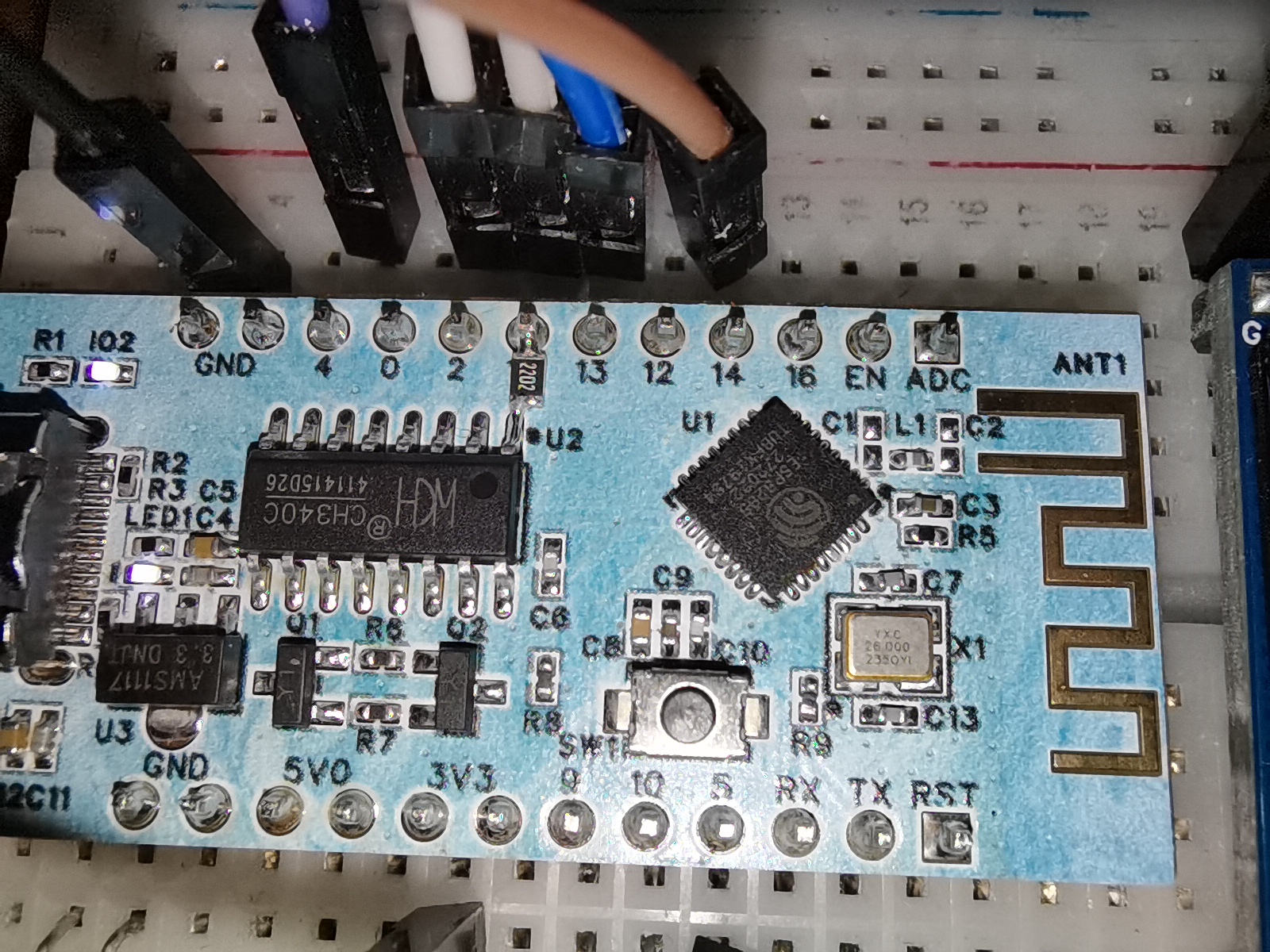

Verification successful!
Due to some mysterious reason, the silkscreen markings on the board and the chip are reversed.
I forgot to draw the pull-down resistor for the GPIO15, but I've added it.
The capacitor for the antenna matching network seems to cause no signal after installation. I haven't learned RF yet, so I'll just use this as is for now.
petal_20231029_215310.mp4
5259ecb1d022e2f5d5be2b1e61e63e35.mp4
PDF_esp8285 development board.zip
Altium_esp8285 development board.zip
PADS_esp8285 development board.zip
BOM_esp8285 development board.xlsx
95466
#Training Camp# Oscilloscope Project Based on GD32 Core Board
Oscilloscope training camp project based on GD32E230C8T6 module
Project Overview: Oscilloscope Training Camp Project Video Showcase Based
on LCSC GD32E230C8T6 Development Board Project Overview Table of Contents Hardware Design Contents Required In-Depth Understanding Design Principles Methods and Principles of Oscilloscope Front-End Processing Circuits AC/DC Signals and Signal Processing Methods in Practice Signal Conditioning Circuit Characteristics of Voltage Follower Circuit Characteristics of Inverting Proportional Amplifier Circuit Characteristics of Non-Inverting Proportional Amplifier Circuit Characteristics of Synthetic Circuits Signal Attenuation Conclusion Analysis Characteristics of Comparator Frequency Measurement Circuit Power Supply Circuit Negative Voltage Generation Circuit Microcontroller Circuit Human-Machine Interaction Circuit Screen Display Circuit Knob Encoder Circuit LED Indicator Circuit Function Key Input Detection Circuit Waveform Output Circuit PCB Layout – Layout Design and Routing Layout Layout Elements Layout Flow Routing Routing Elements Routing Key Points Overall Optimization DRC Check Component Procurement Hardware Soldering Software Design Contents Required In-Depth Understanding of Hardware Design The Importance of Oscilloscope Front-End Processing Circuits: The methods and principles of oscilloscope front-end processing circuits, including signal acquisition, conditioning, and processing. These circuits are responsible for processing the input signals and transmitting them to the microcontroller for identification. Signal Types and Processing: Detailed explanation of signal types (DC and AC signals) and signal processing methods in practice. For example, by utilizing the AC-passing and DC-blocking characteristics of capacitors, DC components can be filtered out, achieving AC coupling. Circuit Principles and Composition: The circuit principles of a digital oscilloscope are analyzed, including the analog front-end processing circuit, microcontroller circuit, power supply circuit, control circuit, trigger circuit, and calibration circuit, explaining the function and role of each part. Characteristics of a voltage follower circuit: The output voltage amplitude is the same as the input voltage, the input resistance is high, and the output resistance is low, as well as its role in the circuit, such as buffering and isolation. Composition of the Human-Machine Interface Circuit: Controlling the functions of the oscilloscope, including buttons, knobs, LEDs, and the display screen. Microcontroller Circuit: GD32 core board, including the acquisition, processing, and output of input signals. Design Principles and Methods of Oscilloscope Front-End Processing Circuits: The main purpose of the oscilloscope front-end processing circuit is to preprocess the input signal so that subsequent circuits can accurately and stably acquire and process the signal. The front-end processing circuit typically includes a signal conditioning circuit and a signal acquisition circuit. The main function of the signal conditioning circuit is to adjust the signal amplitude, bias, and filtering to adapt the signal to the processing requirements of subsequent circuits. The signal conditioning circuit may include amplifiers, filters, bias circuits, etc. The signal acquisition circuit is responsible for converting the conditioned signal into a signal suitable for oscilloscope processing, such as converting analog signals to digital signals. The acquisition circuit may include ADCs (analog-to-digital converters). AC/DC signals and their processing methods in practice: Signal types are mainly divided into DC signals and AC signals. In practice, the signals we encounter are often not ideal waveforms; for example, DC power supplies have ripple, and AC signals may contain DC components. To accurately acquire and process signals, we need to process them appropriately. For AC signals, we can utilize the characteristic of capacitors to pass AC and block DC by connecting capacitors in series in the circuit, thereby filtering out the DC component in the signal. This processing method is called AC coupling. For DC signals, we can process them directly without special coupling processing. Components of an oscilloscope circuit and the specific functions of each circuit: An oscilloscope circuit typically includes a signal input circuit, a signal conditioning circuit, a signal acquisition circuit, and a display circuit. The signal input circuit is responsible for receiving external signals and transmitting them to subsequent circuits. The signal conditioning circuit adjusts the input signal to meet the processing requirements of subsequent circuits. The signal acquisition circuit converts the conditioned signal into a signal suitable for oscilloscope processing. The display circuit then graphically displays the acquired signal for user observation and analysis. The signal conditioning circuit includes a voltage follower and a signal amplification circuit composed of operational amplifiers (op-amps). It's necessary to understand the virtual short and virtual open of op-amps. Virtual Short: A virtual short occurs when an op-amp is in deep negative feedback, making the potentials at the two input terminals equal, as if the two input terminals were shorted together (approximately V+=V-). In negative feedback, a portion of the op-amp's output signal is extracted and fed back to the input terminals. This feedback makes the voltages at the two input terminals (positive and negative) of the op-amp almost equal. Although the voltage difference between the two input terminals is electrically parallel and close to zero, and they are not directly short-circuited, the voltages at the two input terminals are almost equal due to the negative feedback, as if they were short-circuited; hence the term virtual short. Virtual Open: The input impedance of an ideal op-amp is infinite, but the input impedance of a real op-amp is finite. If you apply a voltage to the input terminal of an operational amplifier and then measure the current at that input terminal, you will find that the current reading is close to 0, giving the impression that the operational amplifier is internally disconnected and no current is flowing in. However, it is actually connected. This phenomenon is called a virtual open circuit. It can also be understood using Ohm's Law U=I*R: when the voltage is constant, the current is inversely proportional to the resistance; if the resistance is infinitely large, the current is infinitely small, approaching 0. Characteristics of a Voltage Follower Circuit : A voltage follower circuit is a special circuit whose output voltage is the same as the input voltage and has a very low output impedance, thus providing good buffering and isolation. Voltage follower circuits are commonly used to reduce mutual interference between circuits and improve circuit stability. Furthermore, voltage follower circuits also have high input impedance, low output impedance, and good frequency response, therefore they are widely used in practical circuit design. Characteristics of an Inverting Proportional Amplifier Circuit : The input signal is input from the inverting input terminal of the operational amplifier, resulting in an output with opposite polarity and amplification of the input signal. Characteristics of a Non-Inverting Proportional Amplifier Circuit: The input signal is input from the non-inverting input terminal of the operational amplifier, resulting in an output with the same polarity and amplification of the input signal. Characteristics of a Synthetic Circuit: Signal attenuation conclusion analysis. Characteristics of a Comparator Frequency Measurement Circuit.

To achieve frequency detection, the ADC input signal is compared with a hysteresis comparator to measure the frequency. A hysteresis comparator is a type of voltage comparator. A conventional voltage comparator is a single-threshold comparator, meaning the circuit has only one threshold voltage. However, even a small change in the input voltage near the threshold will cause a significant change in the output voltage. To enhance the circuit's anti-interference capability, positive feedback is introduced into the single-threshold comparator, ensuring signal stability within a certain range. The hysteresis comparator outputs a square wave signal, and the period of the input waveform is calculated using the microcontroller's timer capture function. The threshold
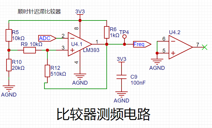
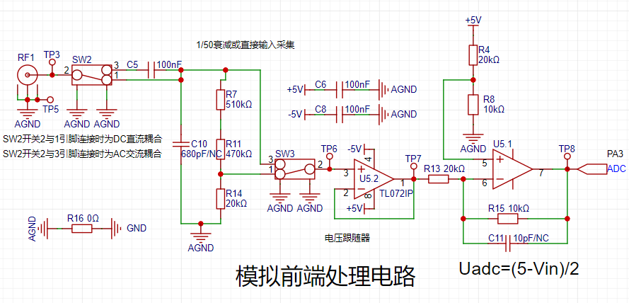
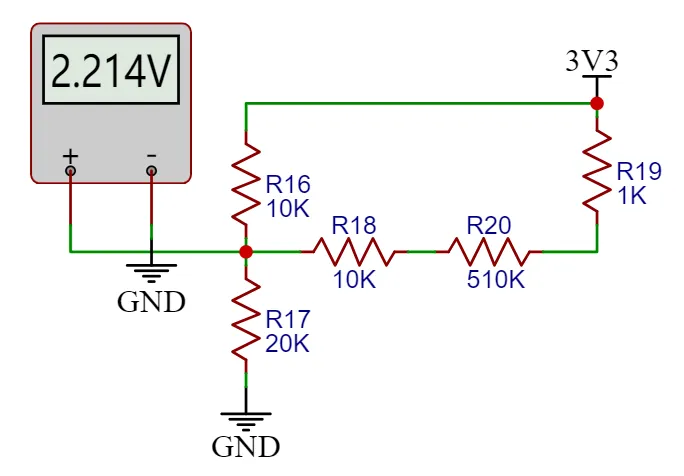
voltage of the hysteresis comparator circuit needs to be analyzed separately based on the op-amp output. The original circuit is shown in the left figure below:
When the output is high, the output terminal is pulled high, and the equivalent circuit is shown in the middle figure below, where Uth = U+ = 2.214V.
When the op-amp output is low, the output terminal is grounded, and the equivalent circuit is shown in the right figure below, where Utl = U- = 2.172V.

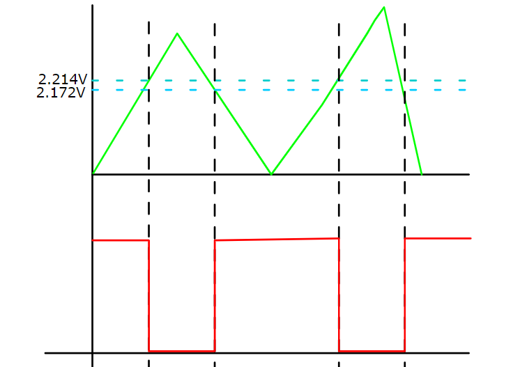
The green line in the diagram below represents the change in signal input voltage. Starting from 0V, the initial output is high. When the input voltage reaches 2.214V, the output signal becomes low, and it remains high until the input signal falls below the lower threshold of 2.172V. The threshold for the next voltage level change can be determined based on the current output state of the comparator. A high threshold (Uth) is used when the output is high, and a low threshold (TtI) is used when the output is low. The thresholds are set close to each other to avoid misidentification caused by signal interference.

Note: The positive input signal of the threshold comparator op-amp is a fixed level here. If a microcontroller with a DAC output is used, the voltage at this point can be freely configured to change the threshold voltage and thus set the trigger mode.
The power supply circuit
project uses the GD32 minimum system board as its core, which has an onboard 5V to 3.3V step-down circuit. Therefore, when designing the expansion board, only a 5V power input circuit needs to be designed. The mainstream Type-C interface was chosen as the input interface, and this interface only has two wires and is a plug-in package, making it easy for beginners to learn soldering. However, it should be noted that this Type-C interface is only for power supply and cannot transmit data. If data transmission is required, the Type-C interface on the core board should be used. SW1 is the main power switch, C1 is the input filter capacitor, and R1 is the current-limiting resistor for LED1. In addition to the power input circuit, the

negative
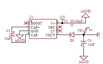
voltage generation circuit uses the XD7660 negative voltage generator to obtain the negative voltage to ensure the operational amplifier's performance in measuring negative voltages. This chip has a simple external circuit, requiring only two capacitors and one diode to operate. Theoretically, with an input voltage of +5V, it can also output a -5V voltage. Due to the chip's internal voltage drop and conversion efficiency, the actual measured negative voltage is approximately -4.3V, which meets the requirements of the operational amplifier.

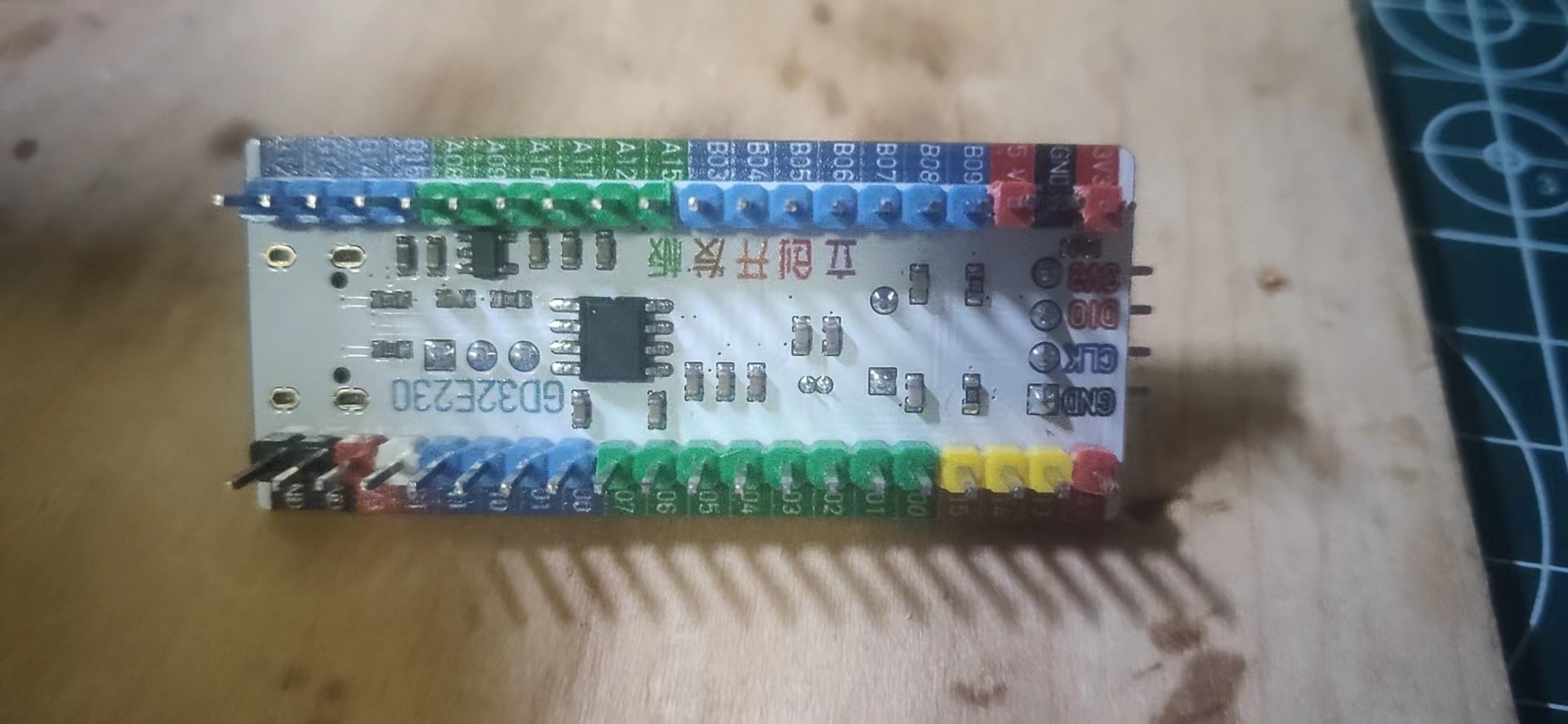
The microcontroller circuit
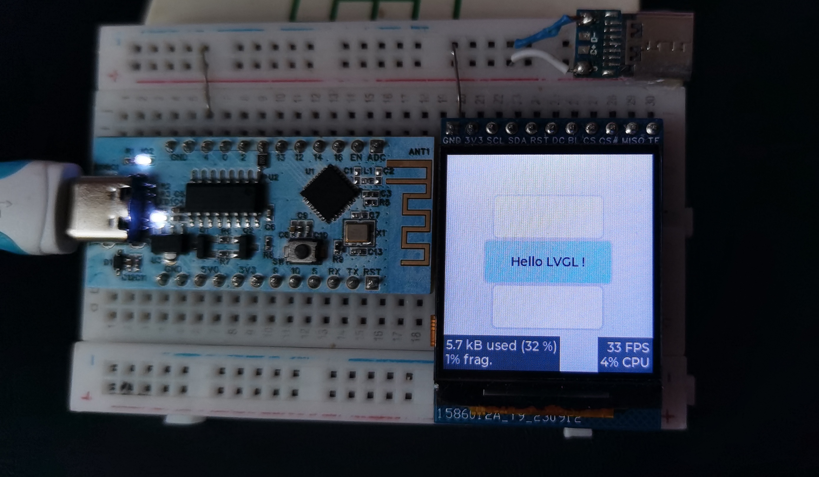
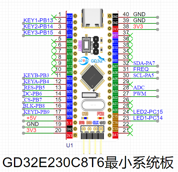
project uses the GD32 minimum system board from the LCSC development board team as the main controller. This development board is a domestically produced board jointly developed by the LCSC team and GigaDevice. It features an onboard CH340 download chip, requiring only one data cable for programming and serial port debugging. It is also compatible with the size and pin configuration of the STM32 minimum system board, allowing for direct replacement.
The human-machine interface
circuit
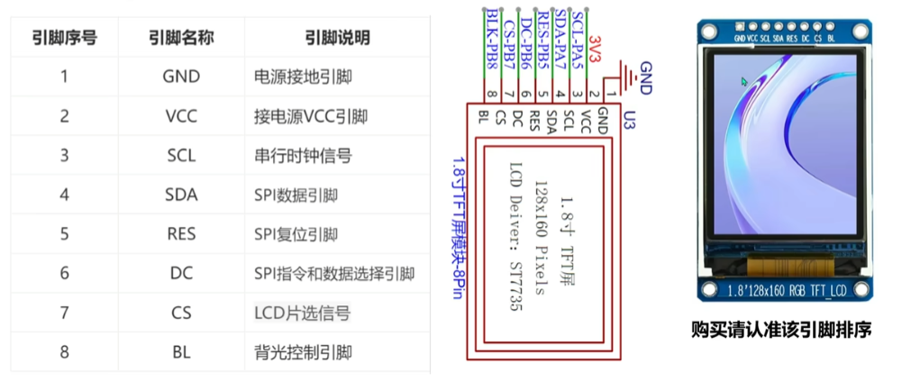
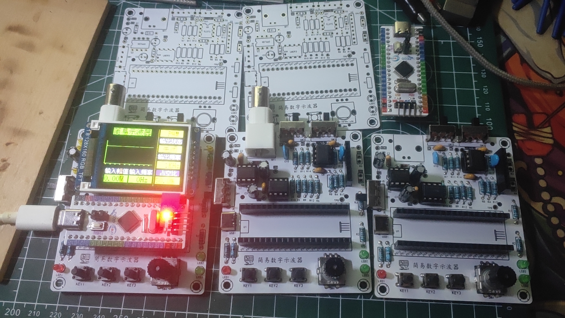
uses a 1.8-inch TFT screen, a color display with 128x160 color pixels. It connects to the microcontroller via four-wire SPI communication and has eight pins.
The rotary encoder circuit
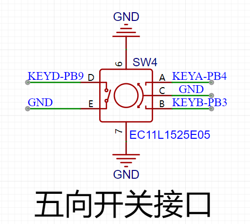
uses an EC11 rotary encoder, a special type of button. It has five pins: pins D and E are similar to ordinary button pins, conducting when pressed and disengaging when released; the remaining three pins A, B, and C are used to detect the rotation direction of the knob. Pin C is the common terminal and can be directly grounded.
In the rotary encoder, there is a phase difference between signal pins A and B. This means that a change in the signal on one pin precedes a change on the other, meaning the two pins do not change simultaneously. Detecting which pin changes first determines whether it's a forward or reverse rotation. The LED
indicator circuit
is relatively simple, using a low-level drive. When the microcontroller pin outputs a low level, a potential difference exists across the LED, causing it to light up; when the microcontroller pin outputs a high level, the LED turns off.

The button input detection circuit
, in addition to the rotary encoder, uses three independent buttons to control the system. One side of each button is directly grounded, and the other side is connected to a microcontroller pin. When the microcontroller pin detects a button press, it connects directly to GND (Ground). The microcontroller receives this grounding signal and then executes the corresponding function. To save hardware costs, debouncing can be incorporated into the software design to prevent false triggering due to button bounce.

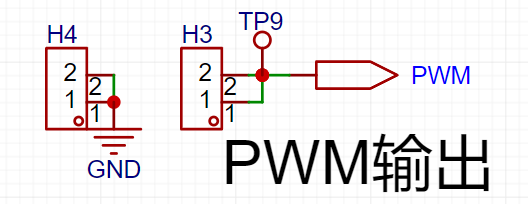
The waveform output circuit,
besides the oscilloscope detection function, has a separate PWM signal output to simulate a simple function generator. By changing the frequency and duty cycle of the output PWM, a simple square wave signal can be output.
PCB Layout – Layout Design and Routing
Layout Key
Elements 1. Divide by module, following the principle of "large to small, difficult to easy". Place important circuits first, others last. 2. Arrange the components according to power supply routing and pin connections between the main controller and peripheral devices. 3. Place connector interfaces to the side to ensure operability and ease of installation and debugging. 4. Special components, such as high-frequency devices and heat-generating devices, need to be handled separately to avoid interference. 5. Ensure proper electrical isolation, such as high-low voltage isolation, analog-to-digital isolation, and high-low frequency isolation. 6. Ensure PCB layout keeps traces as short and straight as possible, and place power supply filter capacitors close to chips. Layout Process : Classify by Module After generating the PCB from the schematic, the next step is to lay out and route the components. When you first switch to the PCB canvas, the component placement is relatively messy. The first step is to classify the components according to their circuit functions. The classification method is to select each circuit module individually on the schematic page, then select the "Layout Transfer" function under the "Design" menu to transfer it to the PCB. Extract the corresponding components and rearrange them. This step is crucial for classification. The standard PCB prototyping size provided by LCSC is 10cm x 10cm. For this project, we set it to 70mm x 80mm. In the Placement menu, select Placement - Board Frame. Place any rectangle on the PCB canvas, click on the rectangle, and change the size to 70mm x 80mm in the properties panel on the right. Set the corner radius to 2mm. After placing the component layout border, place the four screw holes around the perimeter of the board. During layout, first place larger components inside the board for initial planning, ensuring a clear, logical, and user-friendly circuit layout. Use the 3D preview function to check the layout effect in real-time. Layout Tips
When laying out components, there's a light blue line at the connection points; this line is called a flying wire. Its function is to indicate which two pads belong to the same network and require a wire connection. Therefore, flying wires are also called guide wires. However, too many flying wires on a page can affect layout. During routing, flying wires for the GND network can be hidden for a cleaner look. To hide them: In the "Engineering Design" list on the left, select "Network," search for "GND" in the search bar, and then turn off the eye icon next to both AGND and GND in the flying wire list.
Routing
Key Elements:
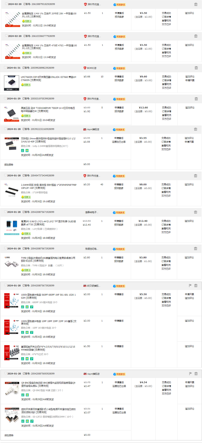
1. Keep trace lengths as short as possible, and traces should run along the direction of the pads. 2. Avoid sharp angles and right angles in PCB design to prevent unnecessary radiation interference. 3. Do not allow one end of the trace to be floating during routing to avoid antenna effects. 4. When routing power supply filters and decoupling capacitors, ensure that current flows through the capacitor filter before powering the components. 5. When designing traces, ensure that the signal line and its loop area are as small as possible, i.e., the minimum loop principle . When routing PCB traces, maximize the width of power and ground lines, prioritizing ground lines over power lines over signal lines. Routing principles : Prioritize straight lines. When corners are necessary, use 135° obtuse angles or rounded corners, minimizing right angles. Power lines should be wider than signal lines. In this project, signal lines are 15mil wide, and power lines are 20mil wide. GND and AGND networks are connected using copper pours. It is recommended to prioritize top-layer routing. If a route is blocked, use vias to connect the top and bottom layers and then continue routing to the bottom layer. Similarly, if a route is blocked on the bottom layer, use vias to connect to the top layer. Layer connections; AGND and GND need to be copper-clad separately at the 0-ohm resistance point. The copper-clad range needs to be adjusted according to the PCB layout. If there are still flying wires after copper-clad, you can place vias of the corresponding nets at the location of the flying wires or adjust the position of the traces to make the nets connect. You can also manually connect the wires to eliminate the flying wires. After the traces are completed, you can select teardrops in the "Tools" menu to strengthen the connection between the pads and the traces. Finally, perform the copper-clad operation. If the traces are moved or adjusted, you should use the shortcut key Shift+B to rebuild the copper-clad. Key elements for overall optimization : 1. Check if the trace width and spacing meet design requirements, and whether there is mutual interference between pads and traces, and between pads themselves. 2. Check if the silkscreen is clear, if the silkscreen placement has a consistent viewing angle, and if interface pins are marked with silkscreen. 3. Whether the optimal layout and routing of critical circuits and signals are adopted, such as minimizing trace length and ensuring electrical isolation. 4. Whether the component numbers and names are accurately labeled to avoid soldering errors. 5. Adjust and optimize some unsatisfactory traces, and check whether the current flow of power lines is reasonable. 6. Before exporting the Gerber file, perform a DRC check and preview of the entire system, and add information such as project name, logo, and version. After the DRC check is completed, click the "Check DRC" button. If no error warnings are displayed, it means that the PCB design is complete. In actual design, various errors may occur, and you can also find and fix these errors by checking the DRC. I'm not a new user of component procurement , and I can only take advantage of the training camp benefits later; therefore, all hardware procurement this time was done through Taobao (only one or two items were missing, so you'll have to find those yourself). The items are incomplete; I'm missing a few things, so I'm being lazy and don't want to look through the pictures. (Time: 3:10 AM, 2:28 AM) Hardware soldering, software design (to be added)
PDF_#Training Camp# Oscilloscope Project Based on GD32 Core Board.zip
Altium_#Training Camp# Oscilloscope Project Based on GD32 Core Board.zip
PADS_#Training Camp# Oscilloscope Project Based on GD32 Core Board.zip
BOM_#Training Camp# Oscilloscope Project Based on GD32 Core Board.xlsx
95467
A very special humidifier
This project is a humidifier I designed myself for JLCPCB's "Electronic Fun" event. Just watch the video to see how unique it is—it's guaranteed to give everyone a shock and make them want to throw it away, haha.
No problem, it's exactly the effect I wanted to achieve. It's an event, after all, all about having fun!
The initial plan is to make a small humidifier with a 3D-coated water tank and top cover. The outer shell features an attractive pattern on the panel, and the overall appearance is quite good when closed. This design includes the schematic diagram, PCB, 3D shell design, and panel design.
The control chip uses an STC main controller, paired with a 108kHz frequency oscillation circuit driven by MOSFETs, which drives the atomizing plate to vibrate at high frequency, instantly atomizing water into small droplets, resulting in a visible atomization effect. Cleverly, the 18650 battery casing is used as a cover, creating the illusion of mist emanating from the 18650, coupled with gradually brightening red LEDs, giving the impression that the battery is short-circuiting, emitting red light and smoke – quite exciting! Give it a try, friends!
The board also includes four WS2812 LEDs, a BLE Bluetooth module, a DHT11 temperature and humidity sensor, and a lithium battery charging board.
Currently, everything is complete except for the code for BLE and DHT11, which are still under development. It has at least achieved the most basic functionality. Future upgrades will include BLE and DHT11 to enable features such as automatic humidification based on humidity, direct Bluetooth control via mobile phone, and deep sleep mode with current less than 1µA when not in use. Stay tuned!
A high-definition video can be viewed on Bilibili: https://www.bilibili.com/video/BV1BC411V795/
For more electronic gadgets, search for '志宇益生菌' on Bilibili to see more interesting project videos.
2.jpg
3.jpg
4.jpg
stc firmware 1.2.hex
Showcase Video - Zhiyu Design.mp4
PDF_A Very Unique Humidifier.zip
Altium - A Very Unique Humidifier.zip
PADS - A Very Unique Humidifier.zip
BOM_A Very Special Humidifier.xlsx
95470
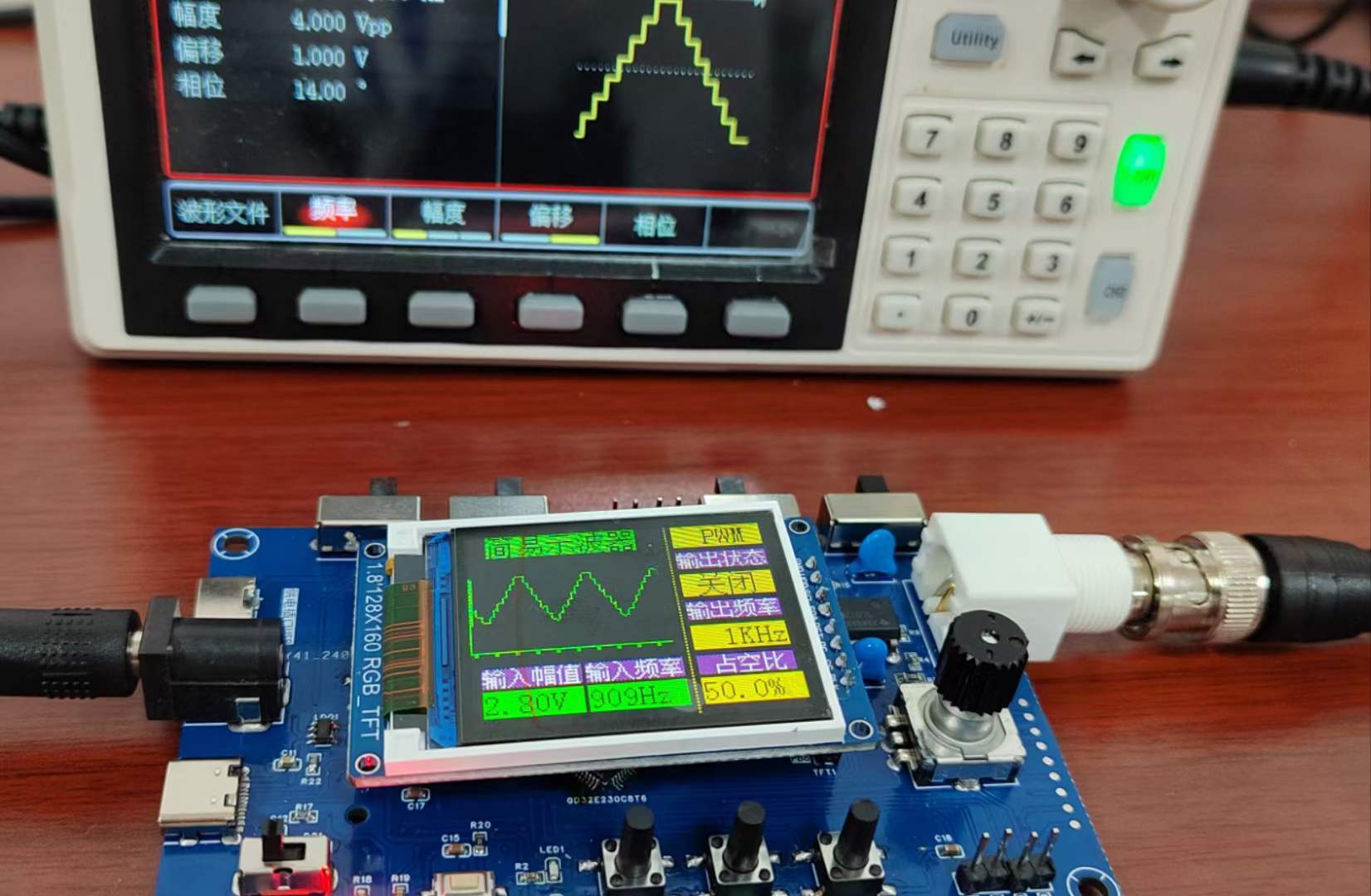
#Training Camp# Simple Digital Oscilloscope - 1186488A
A simple oscilloscope was implemented using the GD32E230C8T6, supporting waveform and frequency measurement as well as PWM output.
I. Schematic Design Description
1. Analog Front-End Processing Circuit
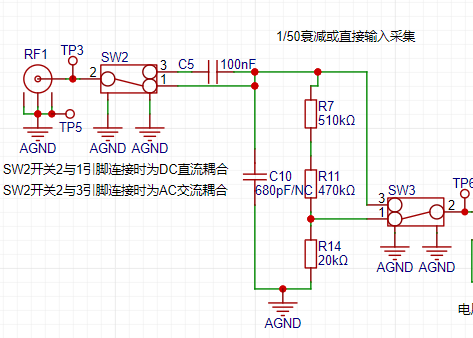
(1) AC/DC Coupling Switching Circuit
Signal types can be divided into DC signals and AC signals. In reality, signals are often not ideal waveforms. For example, a DC power supply signal should be a horizontal DC signal, but there will be power supply ripple (AC signal); when collecting AC signals, DC signals may also be mixed in, affecting the peak-to-peak value of the waveform. In order to ensure accurate measurement of the input AC signal, the DC component in the signal can be filtered out by connecting the capacitor in series with the circuit using the characteristic of the capacitor to pass AC and block DC. This is the concept of AC coupling. DC coupling means that no processing is done on the input signal. The circuit switches the input AC/DC coupling signal through a toggle switch SW6. When switch 2 and 1 are connected together, it is DC coupling. When switch 2 is connected to 3, it is AC coupling.
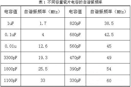
To solve this problem, it is necessary to understand the frequency characteristics of the capacitor. Ideally, the DC blocking capacitor should be as large as possible. However, due to the different self-resonant frequencies of different capacitance values, the capacitor exhibits a capacitive state below the self-resonant frequency and an inductive state above the frequency. The larger the capacitor, the lower its self-resonant frequency. Simply put, a large capacitor passes low frequencies and a small capacitor passes high frequencies. As shown in the upper right figure, when the ceramic capacitor is 0.1uF (100nF), its self-resonant frequency is 4MHz.
Generally, the cutoff frequency of the capacitor is required
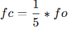
, where fo is the operating frequency in the circuit. Therefore, 100nF is sufficient for this project. However, if the input signal frequency is higher, a smaller capacitor should be selected.
(2) Input signal attenuation circuit
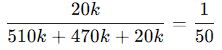
After the AC/DC coupling selection circuit, the input signal is selected by switch SW7 to select two channels. When switches 2 and 3 are connected together, the input signal flows directly into the voltage follower circuit of the next stage. When switches 2 and 1 are connected together, the input signal is attenuated to 1/50 times after passing through the voltage divider network composed of resistors R6, R12 and R15.
According to the calculation of the signal conditioning circuit,
when switches 2 and 3 of SW6 are connected together, the measurable input signal amplitude is -1.6V to 5V.
When switches 2 and 1 of SW6 are connected together, the measurable input signal amplitude is -80V to 250V.
Therefore, when the input signal amplitude is small, the low voltage range can be selected first. If the input signal amplitude is uncertain during measurement, the high voltage range can be used first. If it is within the low voltage range, the low voltage range can be used to obtain a more accurate measurement result, and the protection circuit can be protected at the same time.
(3) Signal Conditioning Circuit
The signal conditioning circuit includes a voltage follower and a signal amplification circuit composed of operational amplifiers. When analyzing this part of the circuit, it is necessary to understand the principles of virtual open and virtual short of operational amplifiers.
Virtual Open:
The input impedance of an ideal operational amplifier is infinite, but the input impedance of a real operational amplifier is finite. If a voltage is applied to the input terminal of the operational amplifier and the current is measured at the input terminal, the current reading will be close to 0, as if the internal operation of the operational amplifier is disconnected and no current flows in, but in reality it is connected. This phenomenon is called virtual open.
It can also be understood using Ohm's law. When the voltage is constant, the current is inversely proportional to the resistance. If the resistance is infinitely large, the current will be infinitely small and close to 0.
Virtual Short:
Virtual short will occur when the operational amplifier is in deep negative feedback, making the potentials of the two input terminals equal, as if the two input terminals are shorted together. It can be approximated as V+=V-.
In negative feedback, a part of the output signal of the operational amplifier is taken out and fed back to the input terminal. This feedback makes the voltage difference between the two input terminals (positive input and negative input) of the operational amplifier approach zero, and the voltages of the two input terminals are almost equal. Although the two input terminals of the op-amp are not electrically short-circuited, due to the negative feedback, the voltages at the two input terminals are almost equal, as if they were short-circuited; hence, this is called a virtual short.
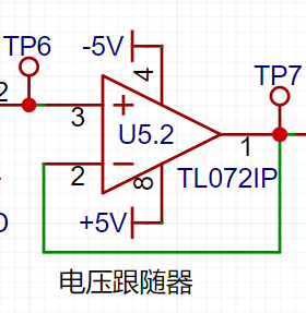
a) Voltage Follower Circuit:
In the U5.2 chip, the op-amp's inverting input pin 2 is connected to the op-amp's output pin 1. Based on the op-amp's virtual short characteristic, V+=V-=Vout. According to the virtual open circuit principle, the operational amplifier's input impedance is relatively large, so the operational amplifier's forward input current is very small. The op-amp's output impedance is small, so the output current is very large. Therefore, the voltage follower here acts as an impedance matcher.
b) Proportional Amplifier Circuit:
When analyzing the circuit constructed by the U5.1 op-amp, it can be decomposed into a non-inverting proportional amplifier circuit and an inverting proportional amplifier circuit for separate analysis before combining them.
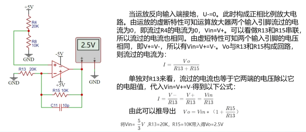
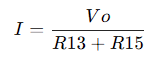
Assuming the op-amp's forward input terminal is grounded, forming an inverting proportional amplifier circuit, the current flowing into the op-amp from the inverting input pin is 0, so R13 and R15 can be considered as connected in series, and therefore the current flowing through them is the same. From the virtual short characteristic, we know that V+ = V- = 0. Therefore,
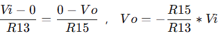
substituting Vi = 1V, R13 = 20KΩ, and R15 = 10KΩ, we get Vo = -0.5V, consistent with the simulation result.
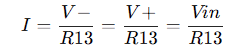
Assuming the op-amp's inverting input is grounded, forming a non-inverting proportional amplifier circuit, the virtual short characteristic of the op-amp means the current flowing through the two input pins is 0, i.e., the current flowing through R4 is 0, Vin = V+. We can consider R13 and R15 as being in series, so the current flowing through them is also the same. From the virtual short characteristic, the voltages of the two input pins are the same, i.e., V+ = V-, therefore Vin = V+ = V-. Vo forms a loop with R13 and R15. The current flowing through it is:
Considering R13 alone, the current is equal to the voltage across it divided by its resistance. Substituting this into Vin=V+=V-, we get the following formula:
Combining the two formulas, we get:

Substituting Vin=5/3V, R13=20K, and R15=10K into the formula, we get Vo=2.5V, consistent with the simulation result.
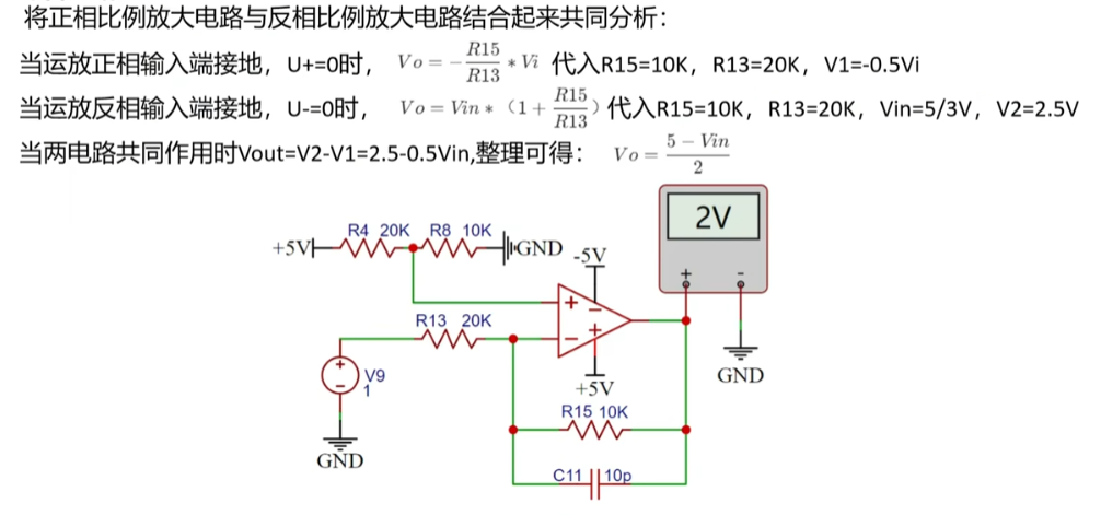
Combining the above non-inverting and inverting amplifier circuits, we get the following formula: Substituting
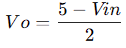
Vin=1 into the formula, we get Vo=2V, consistent with the simulation result.
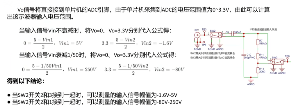
The Vo signal will be directly connected to the ADC pin of the microcontroller. Since the microcontroller acquires the ADC voltage range of 0~3.3V, the input voltage range of the oscilloscope can be calculated.
When the input signal Vin does not decay, substituting Vo=0 and Vo=3.3V into the formula respectively, we get:

When the input signal Vin decays by 1/50, substituting Vo=0 and Vo=3.3V into the formula respectively, we get:
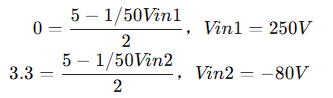
We get the following conclusions:
Low voltage range measurement range: -1.6V~5V, high voltage range measurement range: -80V~250V
(4) Comparator frequency measurement circuit
In order to realize the frequency detection function, the ADC input signal is compared with the input signal through a hysteresis comparator to realize the frequency measurement function. The hysteresis comparator is a type of voltage comparator. The conventional voltage comparator is a single-threshold comparator. There is only one threshold voltage in the circuit, but when the input voltage changes slightly near the threshold, it will cause the output voltage to change. In order to enhance the anti-interference capability of the circuit, positive feedback is introduced on the basis of the single-threshold comparator to ensure the stability of the signal within a certain range. After passing through the hysteresis comparator circuit, a square wave signal is output. The period of the input waveform is calculated by using the timer capture function of the microcontroller.
The threshold voltage of the hysteresis comparator circuit needs to be analyzed separately based on the op-amp output. When the output is high, the output terminal is pulled up to a high level, and the equivalent circuit is shown in the left figure below. We calculate Uth = U+ = 2.214V. When the op-amp output is low, the output terminal is grounded, and the equivalent circuit is shown in the right figure below. We calculate Utl = U- = 2.172V. The
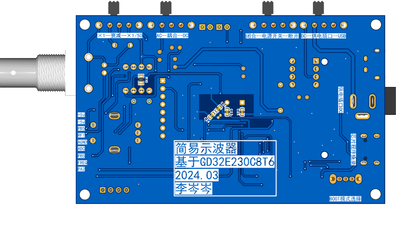
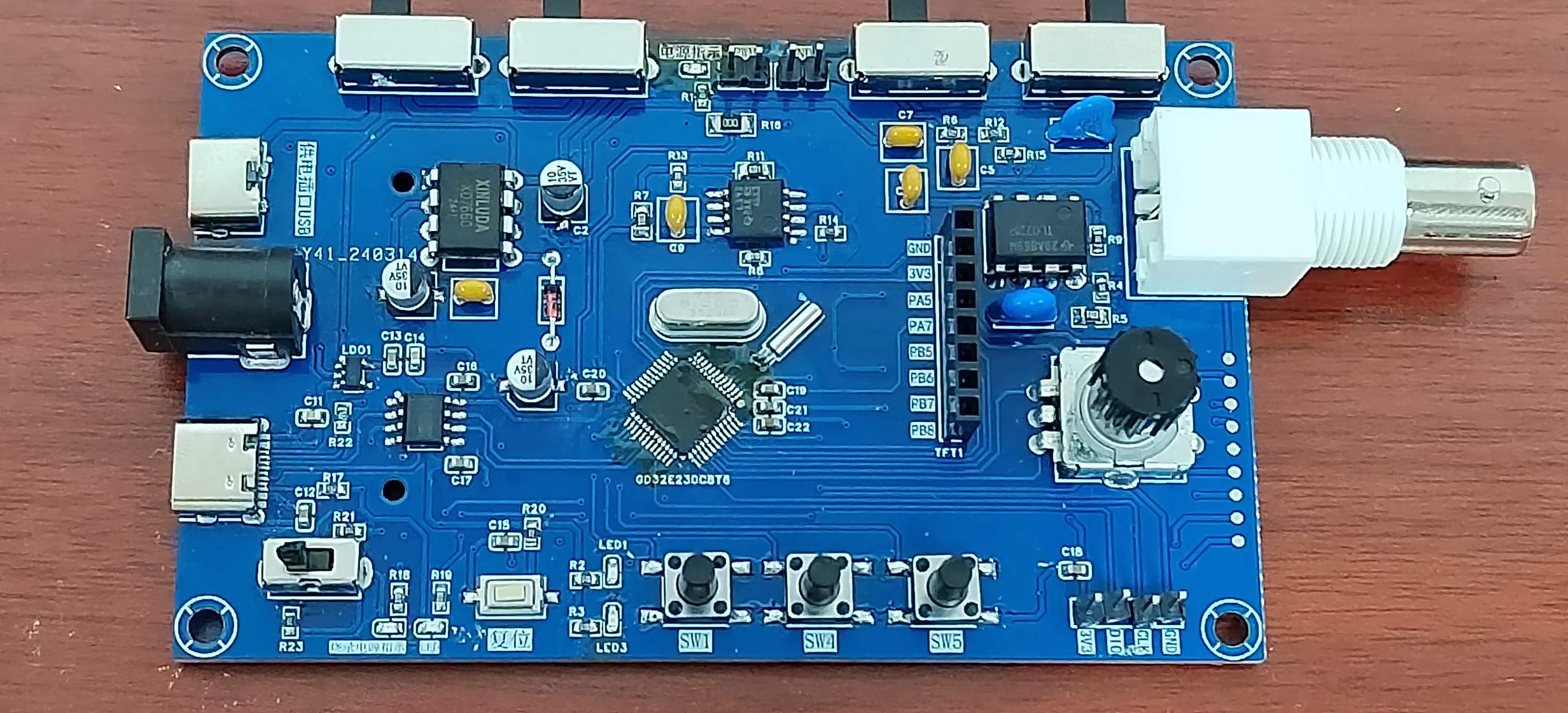
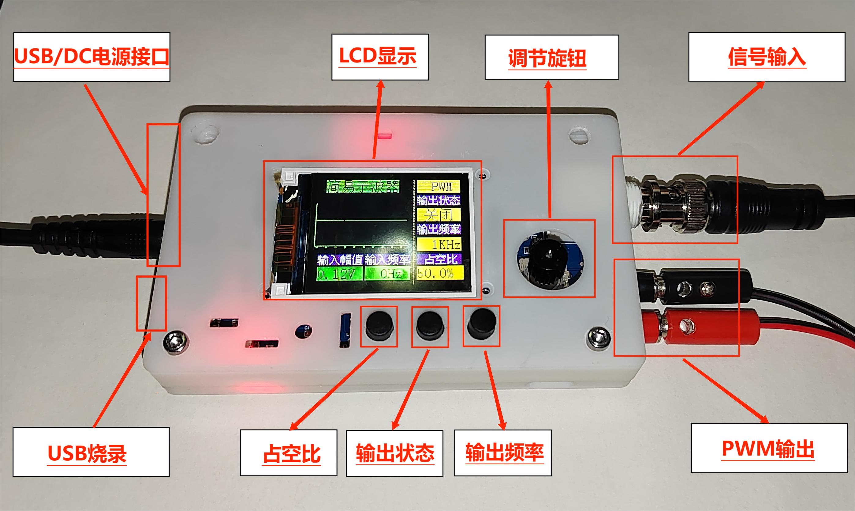
green line in the diagram below represents the change in the signal input voltage. Starting from 0 potential, the initial output state is high. When the input voltage reaches 2.214V, the output signal becomes low, until the input signal falls below the lower threshold of 2.172V, at which point the output becomes high again. The threshold for the next level change can be determined based on the current output state of the comparator. When the output is high, the high threshold Uth is used; when the output is low, the low threshold Ttl is used. The reason for setting the thresholds close together is to avoid misidentification caused by signal interference. 2. Power Control Circuit: This project uses the GD32 as its core, with an onboard 5V to 3.3V step-down circuit. Therefore, only a 5V power input circuit needs to be designed when designing the expansion board. The mainstream Type-C and DC input interfaces are chosen, and this interface has only two wires and is a plug-in package, making it easy for beginners to learn soldering. However, it should be noted that this Type-C interface is only for power supply and cannot transmit data. If data transmission is required, a second Type-C interface can be used. SW2 is the port switching switch, SW3 is the main power switch, C2 is the input filter capacitor, and R1 is the current-limiting resistor for LED2. In addition to the power input circuit, to ensure the operational amplifier's performance in measuring negative voltages, an XD7660 negative voltage generator circuit is used to obtain a negative voltage. This chip has a simple external circuit, requiring only two capacitors and one diode to operate. Theoretically, with an input voltage of +5V, it can also output a -5V voltage. Due to the chip's internal voltage drop and conversion efficiency, the actual measured negative voltage is approximately -4.3V, which still meets the requirements of the operational amplifier. 3. Microcontroller Circuit The microcontroller circuit uses the GD32 minimum system board circuit launched by the LCSC development board team. I personally prefer to integrate the circuit onto one board. The GD32 chip costs a little over one yuan and is very cheap on Taobao. It can also be modularly designed, which is simpler and more convenient. 4. Human-computer interaction circuit (1) LCD screen display circuit 1.8 TFT is a color display screen with 128 x 160 color pixels. It uses four-wire SPI communication to connect with the microcontroller. I bought it on Taobao. I heard from a group member that I lost a few yuan because I didn't get a discount. I am heartbroken! (2) Rotary encoder circuit The rotary encoder is a special kind of button. The EC11 rotary encoder used in this project has five pins. Among them, the DE pins are similar to ordinary button pins. They are turned on when pressed and turned off when released. The other three pins ABC are used to detect the rotation direction of the knob. The C pin is the common terminal and can be directly grounded. In the rotary encoder, there is a phase difference between the two signal pins A and B. That is, after the signal of one pin changes, the signal of the other pin changes accordingly. That is, the two pins do not change at the same time. By detecting which pin changes first, it can be determined whether it is a forward or reverse function. (3) LED indicator circuit The LED indicator circuit design is relatively simple. It adopts a low-level driving method. When the output of the microcontroller pin is low, there is a potential difference between the two ends of the LED, and the LED lights up; when the output of the microcontroller pin is high, the LED turns off. I am a complete novice and can also drive the LED with a transistor. (4) Key input detection circuit In addition to the rotary encoder, this project also uses three independent keys to control the system. One side of the three keys is directly grounded, and the other side is connected to the microcontroller pin. When the microcontroller pin detects that the key is pressed, the microcontroller pin is directly connected to GND ground. After receiving the feedback of the grounding signal of the pin, the microcontroller implements the corresponding function. In order to save hardware costs, a debouncing function can be introduced in the software design to avoid false triggering when the mechanical key bounces. The complete technical documentation for the training camp can be found at: https://www.yuque.com/wldz/jlceda/dso?singleDoc II. Software Design GD32E230C8T6 LCSC official introductory materials Baidu Cloud link: https://pan.baidu.com/s/105CYcL5jc5wnMoSi9HnDlQ?pwd=c8t6 Extraction code: c8t6 - Baidu Cloud link: https://pan.baidu.com/s/105CYcL5jc5wnMoSi9HnDlQ?pwd=c8t6 Extraction code: c8t6 Introductory Tutorial https://lceda001.feishu.cn/wiki/Tlp5wNmPii2oKekezjpcCeA7ndh The complete oscilloscope code is in the attachment; software design technical documents can be found in the official tutorial https://www.yuque.com/wldz/jlceda/dso?singleDoc III. PCB Design Description I'm also a novice in PCB design, and what I drew is barely usable. My ADC cable was a bit too long, but fortunately, there weren't any major problems. Physical verification showed that the basic functions were fine. IV. Physical Demonstration Soldering I brought out my veteran, a yellow 907 that has been with me for three years. It was also my first soldering iron when I started learning electronics. Many of my boards owe their success to it; surface mount resistors and MCUs were directly soldered with solder paste + hot plate/hot air gun. Since I manually applied the solder paste one by one with a syringe, I later corrected the solder joints with the soldering iron when troubleshooting. I usually use 0805 chips for surface mounting, but this time I mostly used 0603 packages, with a few 0805s and one large 0R resistor. Before powering on, I always check for solder bridging and reversed electrolytic capacitors, ensuring all components are soldered correctly before powering on. I changed the BOOT switching mode to a switch, adjusted the BOOT switch, and then used a USB cable to connect and program the Type-C port (or ST-Link, etc.). After adjusting the BOOT switch and pressing the reset button, the display and waveform measurements worked correctly. The problem was that the PWM output switch button functioned the same as the frequency adjustment button. (After troubleshooting, I resoldered the MCU, and the problem was solved. It was probably due to the probe being too thick and too much solder paste causing solder bridging in some areas.)


Problem solved. Powering on and reconnecting the signal generator, other functions tested fine. Started working on the casing and panel...
Currently, I haven't thought of a better solution for these two lines. The best approach is to redesign the PCB, but time is limited, so I'll make do for now.


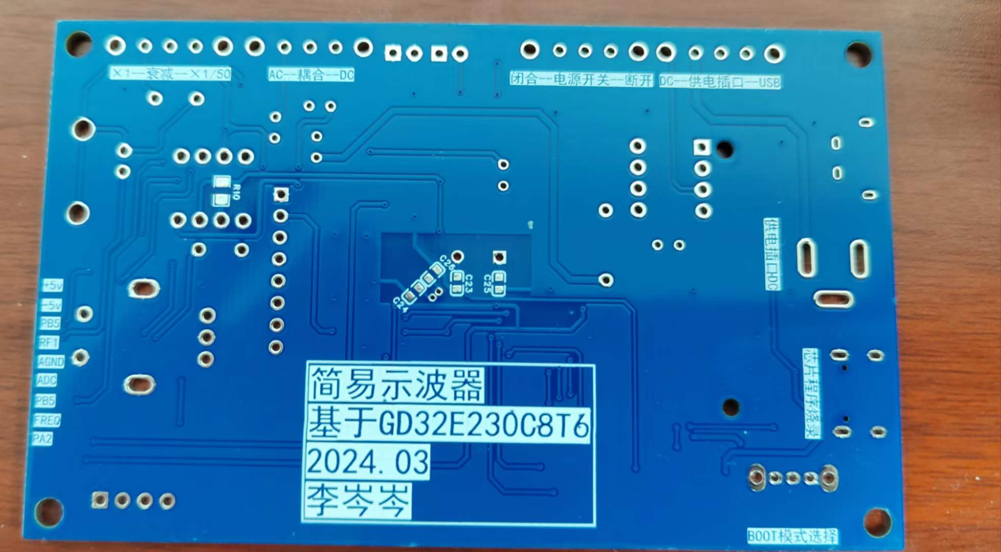
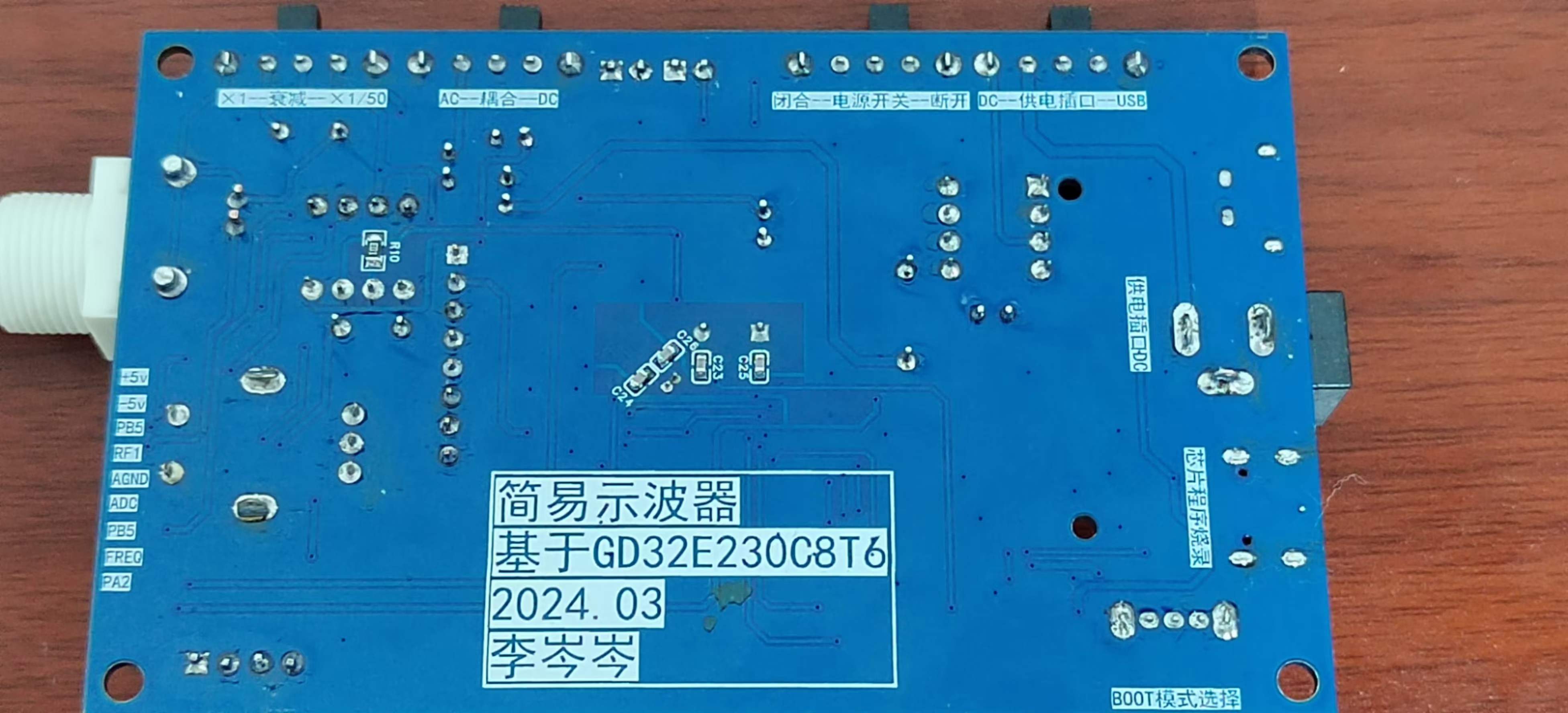
The final physical product looks like this; there's no panel yet, and the design is a bit rough, please forgive me.
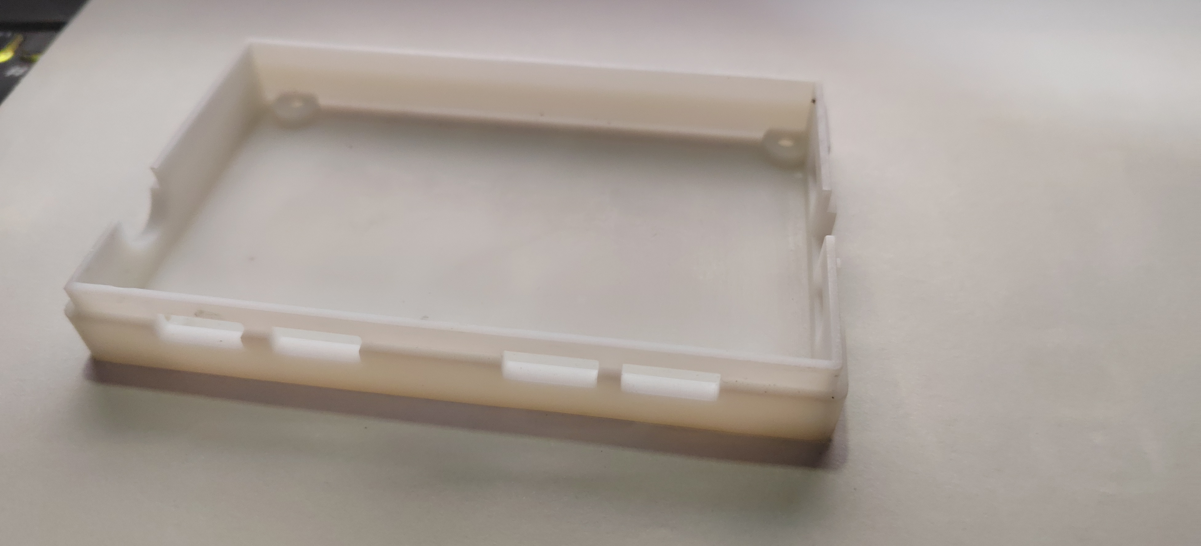
V. 3D Casing Printing :
Top Board ,
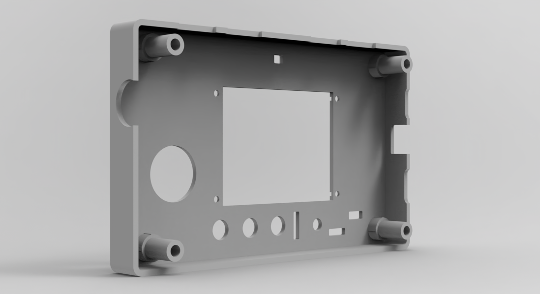
Bottom Board, First Version,

Bottom Board, Second Version: Added ribbon cable grooves and PWM output interface holes.
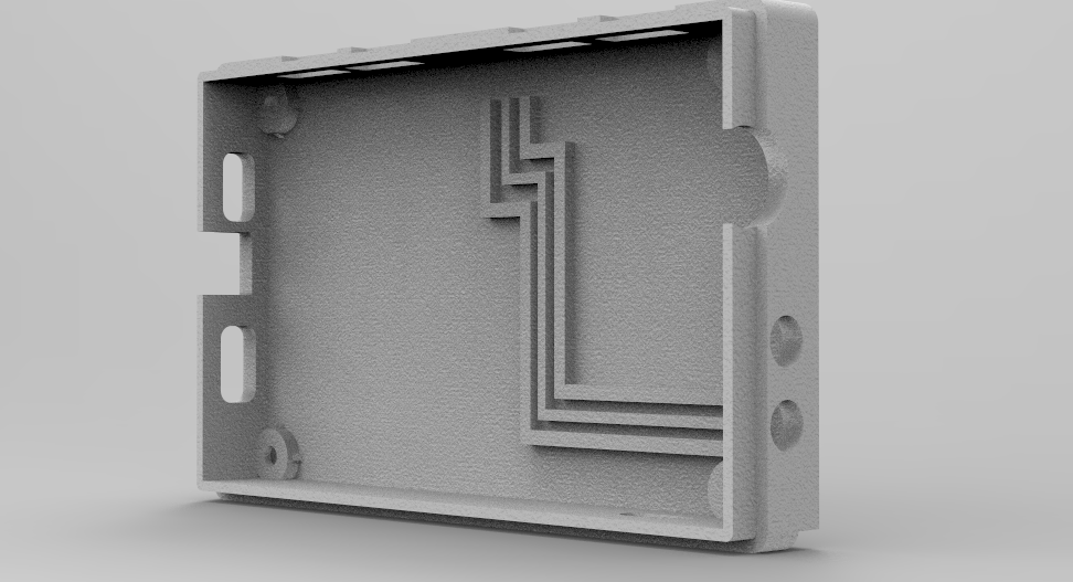
For the second version of the bottom board
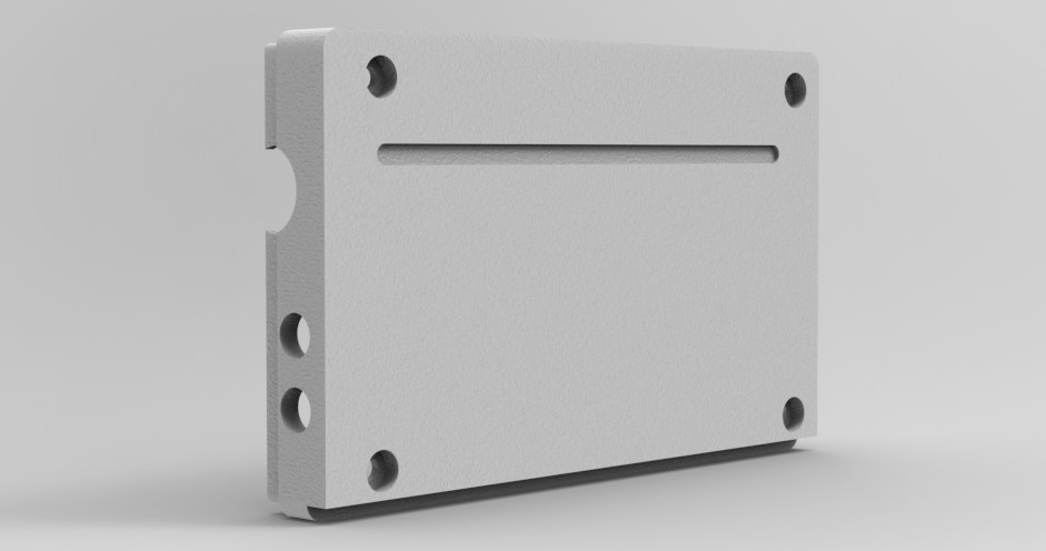
, JLCPCB's 3D Monkey was the first choice for printing the back; the casing printing effect is very good.
Currently, we're still missing modeling for a knob cap and some small parts like switch caps, which we'll work on later when we have time.
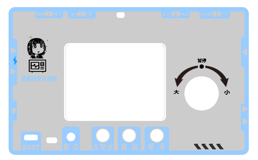
VI. Panel Design:
The cutout positions haven't been fine-tuned; it's just a rough color scheme and appearance design. We'll adjust it according to the casing parameters and then verify it with a physical prototype.
We tried several color schemes and pattern element placements during the design process, and this scheme is currently finalized. (For reference only)
VII. Precautions :
1. Pay attention to whether there are any omissions in the schematic design and whether the component selection or replacement is reasonable.
2. Pay attention to PCB design considerations and signal routing.
3. Pay attention to component soldering issues such as cold solder joints and the presence of short circuits or open circuits.
4. Pay attention to the casing dimensions and cutout dimensions.
VIII. Summary
This training camp provided an initial glimpse into the design of a simple oscilloscope. I gained a lot from the circuit schematic, PCB design, and actual implementation processes. Through continuous exchange with excellent designers, I learned from their strengths and improved my weaknesses. I also thank the engineers at JLCPCB for their hard work and for providing such a platform and activity for learning and exchange. During the design and manufacturing process, I continuously corrected my own shortcomings and cultivated good design habits. Let's strive together, and wish all excellent designers and developers bug-free design.
IX. Demonstration Video
Oscilloscope.hex
3DShell_PCB1_1.zip
Vector graphics.zip
Untitled video - made using Clipchamp.mp4
PDF_#Training Camp# Simple Digital Oscilloscope - 1186488A.zip
Altium_#Training Camp# Simple Digital Oscilloscope - 1186488A.zip
PADS_#Training Camp# Simple Digital Oscilloscope - 1186488A.zip
BOM_#Training Camp# Simple Digital Oscilloscope - 1186488A.xlsx
95472
t113_86 box modified version
Modified from Fanhua Cloud's t113-86 panel: https://oshwhub.com/fanhuacloud/t113-s3-86panel
Thanks to the developer Fan Hua for open-sourcing the T113 86 box and providing detailed SDK installation instructions and
demonstration videos.
The Allwinner T113-S3_86 box application is here, completely outperforming the previous ESP32S3 version!
This modified version includes the following changes:
The removed Bluetooth serial port has been reconnected; one A port has been changed to a C port for ADB use (A to A cables are hard to find); the SPI FLASH has been moved; the wiring has been adjusted; the RST button has been moved and a flashing button has been added; the audio wiring has been adjusted, adding an analog ground and separating it from the digital ground; two test buttons have been added; the RY3730 screen backlight chip is hard to find, so it has been replaced with a SY7200; an analog microphone has been added for audio spectrum pickup.
Note that the microphone is soldered horizontally; the microphone is a high-sensitivity 4015P direct-plug back electrode type 36±1DB anti-interference electret microphone - Taobao (taobao.com). For
DIY instructions, please refer to the original Fan Hua engineering
exchange group 787148555. The answer is Tai Chi style; for DIY projects, you can join the group.
IMG_4665.MP4
PDF_t113_86 Box Modified Version.zip
Altium_t113_86 Box Modified Version.zip
PADS_t113_86 Box Modified Version.zip
BOM_t113_86 box modified version.xlsx
95473
electronic


 京公网安备 11010802033920号

 171-006-6P-.110-P3MH


