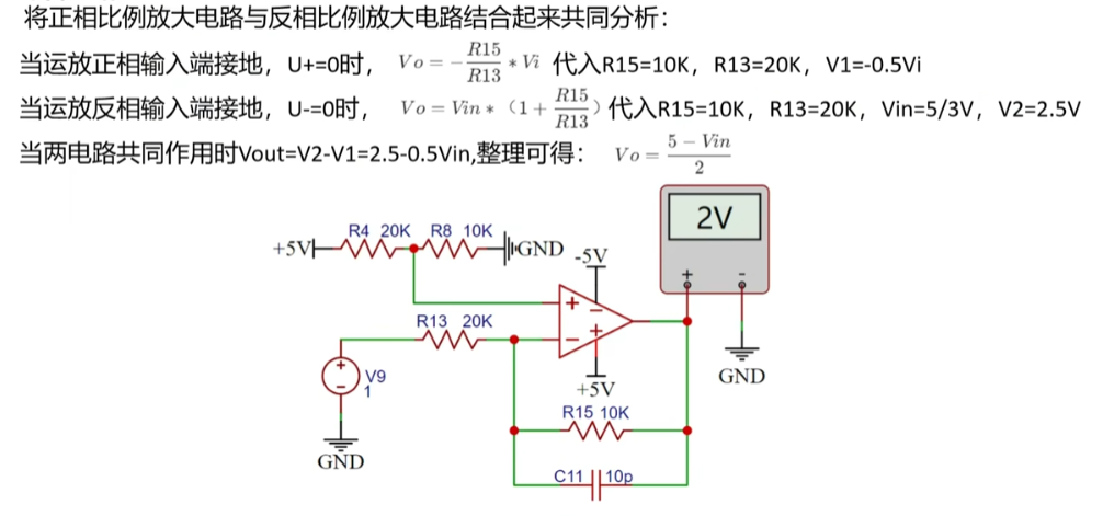
Project Overview: Oscilloscope Training Camp Project Video Showcase Based
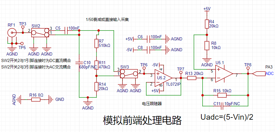
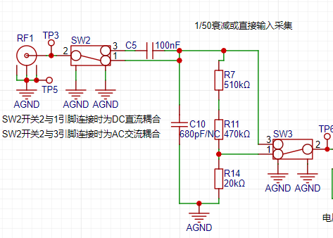
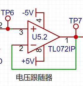
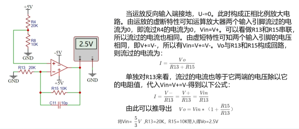
on LCSC GD32E230C8T6 Development Board Project Overview Table of Contents Hardware Design Contents Required In-Depth Understanding Design Principles Methods and Principles of Oscilloscope Front-End Processing Circuits AC/DC Signals and Signal Processing Methods in Practice Signal Conditioning Circuit Characteristics of Voltage Follower Circuit Characteristics of Inverting Proportional Amplifier Circuit Characteristics of Non-Inverting Proportional Amplifier Circuit Characteristics of Synthetic Circuits Signal Attenuation Conclusion Analysis Characteristics of Comparator Frequency Measurement Circuit Power Supply Circuit Negative Voltage Generation Circuit Microcontroller Circuit Human-Machine Interaction Circuit Screen Display Circuit Knob Encoder Circuit LED Indicator Circuit Function Key Input Detection Circuit Waveform Output Circuit PCB Layout – Layout Design and Routing Layout Layout Elements Layout Flow Routing Routing Elements Routing Key Points Overall Optimization DRC Check Component Procurement Hardware Soldering Software Design Contents Required In-Depth Understanding of Hardware Design The Importance of Oscilloscope Front-End Processing Circuits: The methods and principles of oscilloscope front-end processing circuits, including signal acquisition, conditioning, and processing. These circuits are responsible for processing the input signals and transmitting them to the microcontroller for identification. Signal Types and Processing: Detailed explanation of signal types (DC and AC signals) and signal processing methods in practice. For example, by utilizing the AC-passing and DC-blocking characteristics of capacitors, DC components can be filtered out, achieving AC coupling. Circuit Principles and Composition: The circuit principles of a digital oscilloscope are analyzed, including the analog front-end processing circuit, microcontroller circuit, power supply circuit, control circuit, trigger circuit, and calibration circuit, explaining the function and role of each part. Characteristics of a voltage follower circuit: The output voltage amplitude is the same as the input voltage, the input resistance is high, and the output resistance is low, as well as its role in the circuit, such as buffering and isolation. Composition of the Human-Machine Interface Circuit: Controlling the functions of the oscilloscope, including buttons, knobs, LEDs, and the display screen. Microcontroller Circuit: GD32 core board, including the acquisition, processing, and output of input signals. Design Principles and Methods of Oscilloscope Front-End Processing Circuits: The main purpose of the oscilloscope front-end processing circuit is to preprocess the input signal so that subsequent circuits can accurately and stably acquire and process the signal. The front-end processing circuit typically includes a signal conditioning circuit and a signal acquisition circuit. The main function of the signal conditioning circuit is to adjust the signal amplitude, bias, and filtering to adapt the signal to the processing requirements of subsequent circuits. The signal conditioning circuit may include amplifiers, filters, bias circuits, etc. The signal acquisition circuit is responsible for converting the conditioned signal into a signal suitable for oscilloscope processing, such as converting analog signals to digital signals. The acquisition circuit may include ADCs (analog-to-digital converters). AC/DC signals and their processing methods in practice: Signal types are mainly divided into DC signals and AC signals. In practice, the signals we encounter are often not ideal waveforms; for example, DC power supplies have ripple, and AC signals may contain DC components. To accurately acquire and process signals, we need to process them appropriately. For AC signals, we can utilize the characteristic of capacitors to pass AC and block DC by connecting capacitors in series in the circuit, thereby filtering out the DC component in the signal. This processing method is called AC coupling. For DC signals, we can process them directly without special coupling processing. Components of an oscilloscope circuit and the specific functions of each circuit: An oscilloscope circuit typically includes a signal input circuit, a signal conditioning circuit, a signal acquisition circuit, and a display circuit. The signal input circuit is responsible for receiving external signals and transmitting them to subsequent circuits. The signal conditioning circuit adjusts the input signal to meet the processing requirements of subsequent circuits. The signal acquisition circuit converts the conditioned signal into a signal suitable for oscilloscope processing. The display circuit then graphically displays the acquired signal for user observation and analysis. The signal conditioning circuit includes a voltage follower and a signal amplification circuit composed of operational amplifiers (op-amps). It's necessary to understand the virtual short and virtual open of op-amps. Virtual Short: A virtual short occurs when an op-amp is in deep negative feedback, making the potentials at the two input terminals equal, as if the two input terminals were shorted together (approximately V+=V-). In negative feedback, a portion of the op-amp's output signal is extracted and fed back to the input terminals. This feedback makes the voltages at the two input terminals (positive and negative) of the op-amp almost equal. Although the voltage difference between the two input terminals is electrically parallel and close to zero, and they are not directly short-circuited, the voltages at the two input terminals are almost equal due to the negative feedback, as if they were short-circuited; hence the term virtual short. Virtual Open: The input impedance of an ideal op-amp is infinite, but the input impedance of a real op-amp is finite. If you apply a voltage to the input terminal of an operational amplifier and then measure the current at that input terminal, you will find that the current reading is close to 0, giving the impression that the operational amplifier is internally disconnected and no current is flowing in. However, it is actually connected. This phenomenon is called a virtual open circuit. It can also be understood using Ohm's Law U=I*R: when the voltage is constant, the current is inversely proportional to the resistance; if the resistance is infinitely large, the current is infinitely small, approaching 0. Characteristics of a Voltage Follower Circuit : A voltage follower circuit is a special circuit whose output voltage is the same as the input voltage and has a very low output impedance, thus providing good buffering and isolation. Voltage follower circuits are commonly used to reduce mutual interference between circuits and improve circuit stability. Furthermore, voltage follower circuits also have high input impedance, low output impedance, and good frequency response, therefore they are widely used in practical circuit design. Characteristics of an Inverting Proportional Amplifier Circuit : The input signal is input from the inverting input terminal of the operational amplifier, resulting in an output with opposite polarity and amplification of the input signal. Characteristics of a Non-Inverting Proportional Amplifier Circuit: The input signal is input from the non-inverting input terminal of the operational amplifier, resulting in an output with the same polarity and amplification of the input signal. Characteristics of a Synthetic Circuit: Signal attenuation conclusion analysis. Characteristics of a Comparator Frequency Measurement Circuit.

To achieve frequency detection, the ADC input signal is compared with a hysteresis comparator to measure the frequency. A hysteresis comparator is a type of voltage comparator. A conventional voltage comparator is a single-threshold comparator, meaning the circuit has only one threshold voltage. However, even a small change in the input voltage near the threshold will cause a significant change in the output voltage. To enhance the circuit's anti-interference capability, positive feedback is introduced into the single-threshold comparator, ensuring signal stability within a certain range. The hysteresis comparator outputs a square wave signal, and the period of the input waveform is calculated using the microcontroller's timer capture function. The threshold
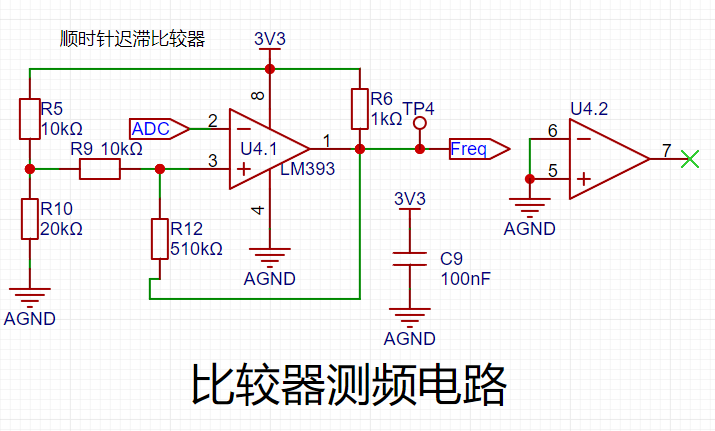
voltage of the hysteresis comparator circuit needs to be analyzed separately based on the op-amp output. The original circuit is shown in the left figure below:
When the output is high, the output terminal is pulled high, and the equivalent circuit is shown in the middle figure below, where Uth = U+ = 2.214V.
When the op-amp output is low, the output terminal is grounded, and the equivalent circuit is shown in the right figure below, where Utl = U- = 2.172V.

The green line in the diagram below represents the change in signal input voltage. Starting from 0V, the initial output is high. When the input voltage reaches 2.214V, the output signal becomes low, and it remains high until the input signal falls below the lower threshold of 2.172V. The threshold for the next voltage level change can be determined based on the current output state of the comparator. A high threshold (Uth) is used when the output is high, and a low threshold (TtI) is used when the output is low. The thresholds are set close to each other to avoid misidentification caused by signal interference.

Note: The positive input signal of the threshold comparator op-amp is a fixed level here. If a microcontroller with a DAC output is used, the voltage at this point can be freely configured to change the threshold voltage and thus set the trigger mode.
The power supply circuit
project uses the GD32 minimum system board as its core, which has an onboard 5V to 3.3V step-down circuit. Therefore, when designing the expansion board, only a 5V power input circuit needs to be designed. The mainstream Type-C interface was chosen as the input interface, and this interface only has two wires and is a plug-in package, making it easy for beginners to learn soldering. However, it should be noted that this Type-C interface is only for power supply and cannot transmit data. If data transmission is required, the Type-C interface on the core board should be used. SW1 is the main power switch, C1 is the input filter capacitor, and R1 is the current-limiting resistor for LED1. In addition to the power input circuit, the

negative
voltage generation circuit uses the XD7660 negative voltage generator to obtain the negative voltage to ensure the operational amplifier's performance in measuring negative voltages. This chip has a simple external circuit, requiring only two capacitors and one diode to operate. Theoretically, with an input voltage of +5V, it can also output a -5V voltage. Due to the chip's internal voltage drop and conversion efficiency, the actual measured negative voltage is approximately -4.3V, which meets the requirements of the operational amplifier.

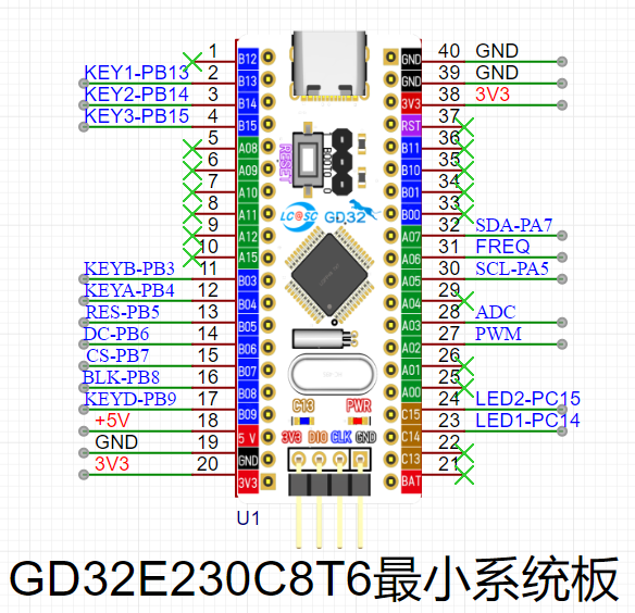
The microcontroller circuit
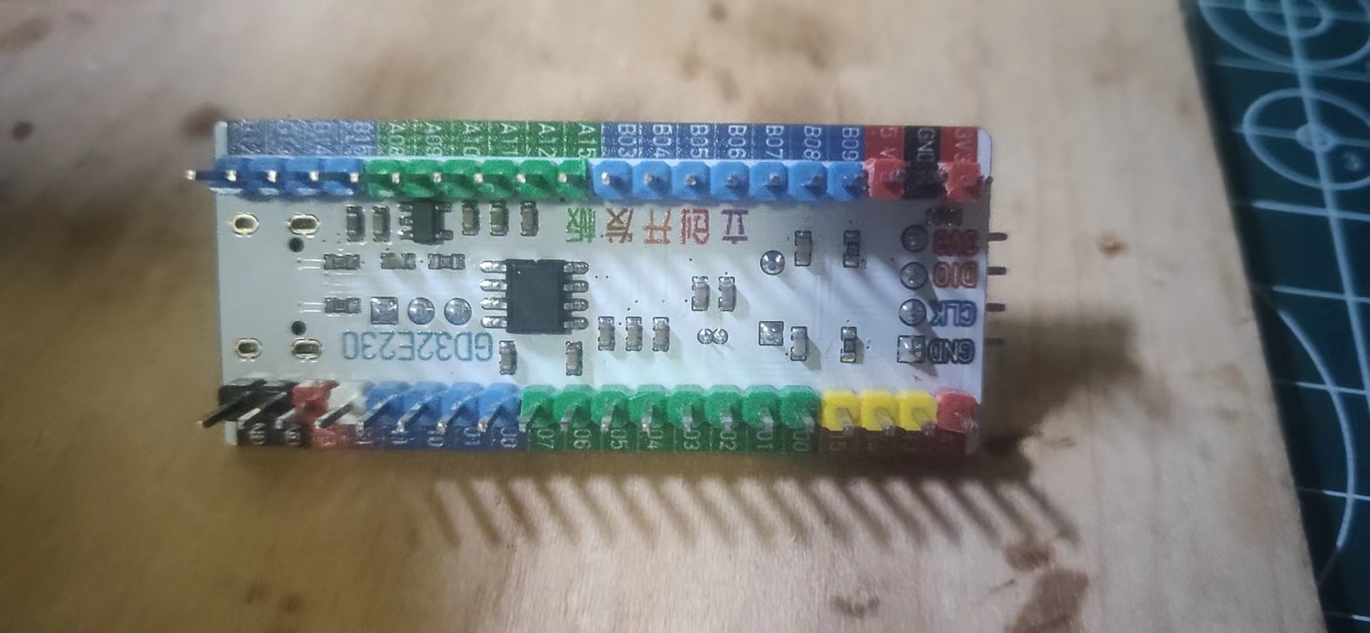
project uses the GD32 minimum system board from the LCSC development board team as the main controller. This development board is a domestically produced board jointly developed by the LCSC team and GigaDevice. It features an onboard CH340 download chip, requiring only one data cable for programming and serial port debugging. It is also compatible with the size and pin configuration of the STM32 minimum system board, allowing for direct replacement.
The human-machine interface
circuit
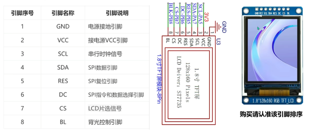
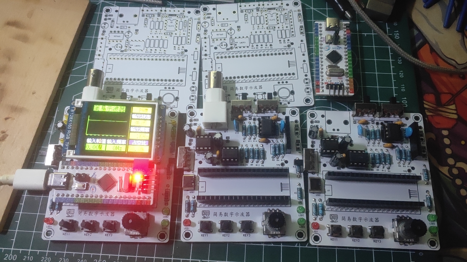
uses a 1.8-inch TFT screen, a color display with 128x160 color pixels. It connects to the microcontroller via four-wire SPI communication and has eight pins.
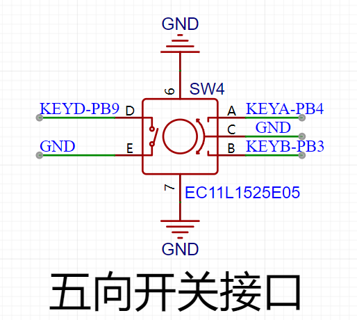
The rotary encoder circuit
uses an EC11 rotary encoder, a special type of button. It has five pins: pins D and E are similar to ordinary button pins, conducting when pressed and disengaging when released; the remaining three pins A, B, and C are used to detect the rotation direction of the knob. Pin C is the common terminal and can be directly grounded.
In the rotary encoder, there is a phase difference between signal pins A and B. This means that a change in the signal on one pin precedes a change on the other, meaning the two pins do not change simultaneously. Detecting which pin changes first determines whether it's a forward or reverse rotation. The LED
indicator circuit
is relatively simple, using a low-level drive. When the microcontroller pin outputs a low level, a potential difference exists across the LED, causing it to light up; when the microcontroller pin outputs a high level, the LED turns off.

The button input detection circuit
, in addition to the rotary encoder, uses three independent buttons to control the system. One side of each button is directly grounded, and the other side is connected to a microcontroller pin. When the microcontroller pin detects a button press, it connects directly to GND (Ground). The microcontroller receives this grounding signal and then executes the corresponding function. To save hardware costs, debouncing can be incorporated into the software design to prevent false triggering due to button bounce.

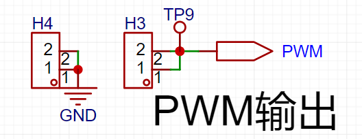
The waveform output circuit,
besides the oscilloscope detection function, has a separate PWM signal output to simulate a simple function generator. By changing the frequency and duty cycle of the output PWM, a simple square wave signal can be output.
PCB Layout – Layout Design and Routing
Layout Key
Elements 1. Divide by module, following the principle of "large to small, difficult to easy". Place important circuits first, others last. 2. Arrange the components according to power supply routing and pin connections between the main controller and peripheral devices. 3. Place connector interfaces to the side to ensure operability and ease of installation and debugging. 4. Special components, such as high-frequency devices and heat-generating devices, need to be handled separately to avoid interference. 5. Ensure proper electrical isolation, such as high-low voltage isolation, analog-to-digital isolation, and high-low frequency isolation. 6. Ensure PCB layout keeps traces as short and straight as possible, and place power supply filter capacitors close to chips. Layout Process : Classify by Module After generating the PCB from the schematic, the next step is to lay out and route the components. When you first switch to the PCB canvas, the component placement is relatively messy. The first step is to classify the components according to their circuit functions. The classification method is to select each circuit module individually on the schematic page, then select the "Layout Transfer" function under the "Design" menu to transfer it to the PCB. Extract the corresponding components and rearrange them. This step is crucial for classification. The standard PCB prototyping size provided by LCSC is 10cm x 10cm. For this project, we set it to 70mm x 80mm. In the Placement menu, select Placement - Board Frame. Place any rectangle on the PCB canvas, click on the rectangle, and change the size to 70mm x 80mm in the properties panel on the right. Set the corner radius to 2mm. After placing the component layout border, place the four screw holes around the perimeter of the board. During layout, first place larger components inside the board for initial planning, ensuring a clear, logical, and user-friendly circuit layout. Use the 3D preview function to check the layout effect in real-time. Layout Tips
When laying out components, there's a light blue line at the connection points; this line is called a flying wire. Its function is to indicate which two pads belong to the same network and require a wire connection. Therefore, flying wires are also called guide wires. However, too many flying wires on a page can affect layout. During routing, flying wires for the GND network can be hidden for a cleaner look. To hide them: In the "Engineering Design" list on the left, select "Network," search for "GND" in the search bar, and then turn off the eye icon next to both AGND and GND in the flying wire list.
Routing
Key Elements:
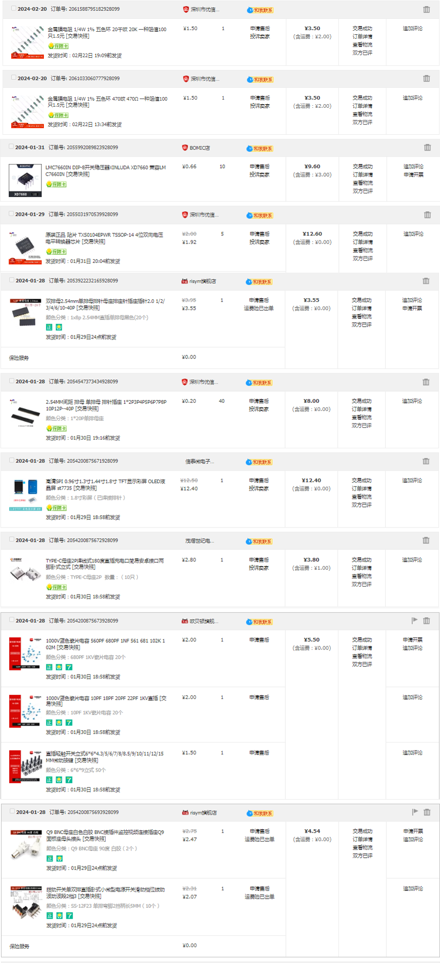
1. Keep trace lengths as short as possible, and traces should run along the direction of the pads. 2. Avoid sharp angles and right angles in PCB design to prevent unnecessary radiation interference. 3. Do not allow one end of the trace to be floating during routing to avoid antenna effects. 4. When routing power supply filters and decoupling capacitors, ensure that current flows through the capacitor filter before powering the components. 5. When designing traces, ensure that the signal line and its loop area are as small as possible, i.e., the minimum loop principle . When routing PCB traces, maximize the width of power and ground lines, prioritizing ground lines over power lines over signal lines. Routing principles : Prioritize straight lines. When corners are necessary, use 135° obtuse angles or rounded corners, minimizing right angles. Power lines should be wider than signal lines. In this project, signal lines are 15mil wide, and power lines are 20mil wide. GND and AGND networks are connected using copper pours. It is recommended to prioritize top-layer routing. If a route is blocked, use vias to connect the top and bottom layers and then continue routing to the bottom layer. Similarly, if a route is blocked on the bottom layer, use vias to connect to the top layer. Layer connections; AGND and GND need to be copper-clad separately at the 0-ohm resistance point. The copper-clad range needs to be adjusted according to the PCB layout. If there are still flying wires after copper-clad, you can place vias of the corresponding nets at the location of the flying wires or adjust the position of the traces to make the nets connect. You can also manually connect the wires to eliminate the flying wires. After the traces are completed, you can select teardrops in the "Tools" menu to strengthen the connection between the pads and the traces. Finally, perform the copper-clad operation. If the traces are moved or adjusted, you should use the shortcut key Shift+B to rebuild the copper-clad. Key elements for overall optimization : 1. Check if the trace width and spacing meet design requirements, and whether there is mutual interference between pads and traces, and between pads themselves. 2. Check if the silkscreen is clear, if the silkscreen placement has a consistent viewing angle, and if interface pins are marked with silkscreen. 3. Whether the optimal layout and routing of critical circuits and signals are adopted, such as minimizing trace length and ensuring electrical isolation. 4. Whether the component numbers and names are accurately labeled to avoid soldering errors. 5. Adjust and optimize some unsatisfactory traces, and check whether the current flow of power lines is reasonable. 6. Before exporting the Gerber file, perform a DRC check and preview of the entire system, and add information such as project name, logo, and version. After the DRC check is completed, click the "Check DRC" button. If no error warnings are displayed, it means that the PCB design is complete. In actual design, various errors may occur, and you can also find and fix these errors by checking the DRC. I'm not a new user of component procurement , and I can only take advantage of the training camp benefits later; therefore, all hardware procurement this time was done through Taobao (only one or two items were missing, so you'll have to find those yourself). The items are incomplete; I'm missing a few things, so I'm being lazy and don't want to look through the pictures. (Time: 3:10 AM, 2:28 AM) Hardware soldering, software design (to be added)


 京公网安备 11010802033920号

 F871DM334J330A


