This article presents an open-source 205W buck-boost fast charging module (140W + 65W) based on IP6557 and IP6538 chips. One channel supports PD3.1 protocol with a maximum output of 28V 5A via a USB-C port, while the other channel is a USB-A + USB-C port with a maximum output of 65W (20V 3.25A). It can be used with a 24V 10A switching power supply to form a low-cost 205W fast charger! The maximum conversion efficiency is 96.7%
, which is average; please don't criticize too harshly. If you have any suggestions for improvement, please leave them in the comments section. Friendly discussion is welcome.
Complete documentation is provided, allowing you to easily replicate the module. The download link is at the end of the article!
Video demonstration: https://www.bilibili.com/video/BV1HM4m1U7Hc/
Electronics/Microcontroller Technology Exchange QQ Group: 820537762
Introduction:
This fast charging module, when used with a 24V 10A switching power supply, can form a low-cost 205W dual-channel fast charger! (A 24V 10A power supply can be bought for around 30 yuan.)
With a cigarette lighter plug to DC male/XT30 adapter cable, you can turn it into a car fast charger, a 140W + 65W car charger!
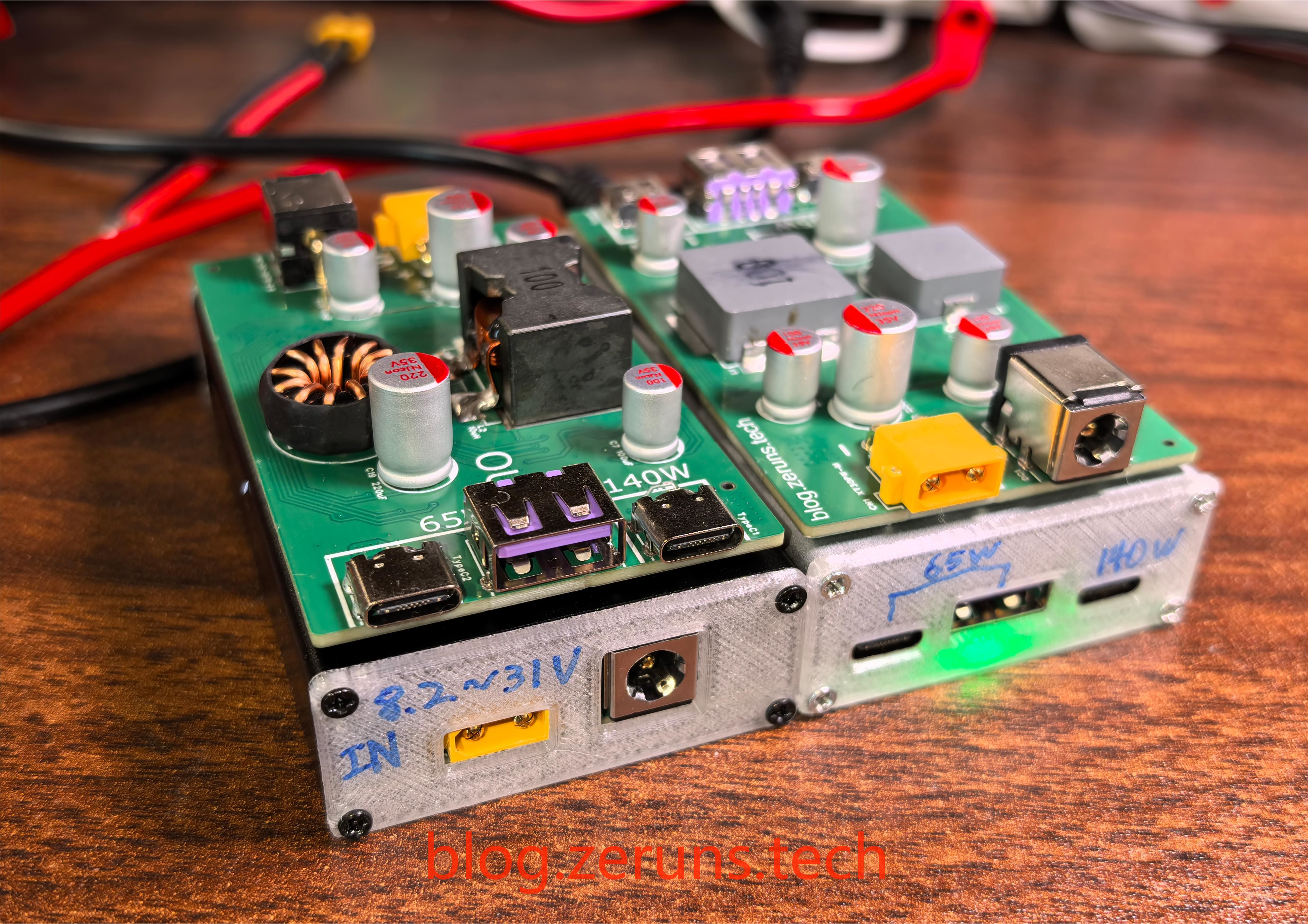
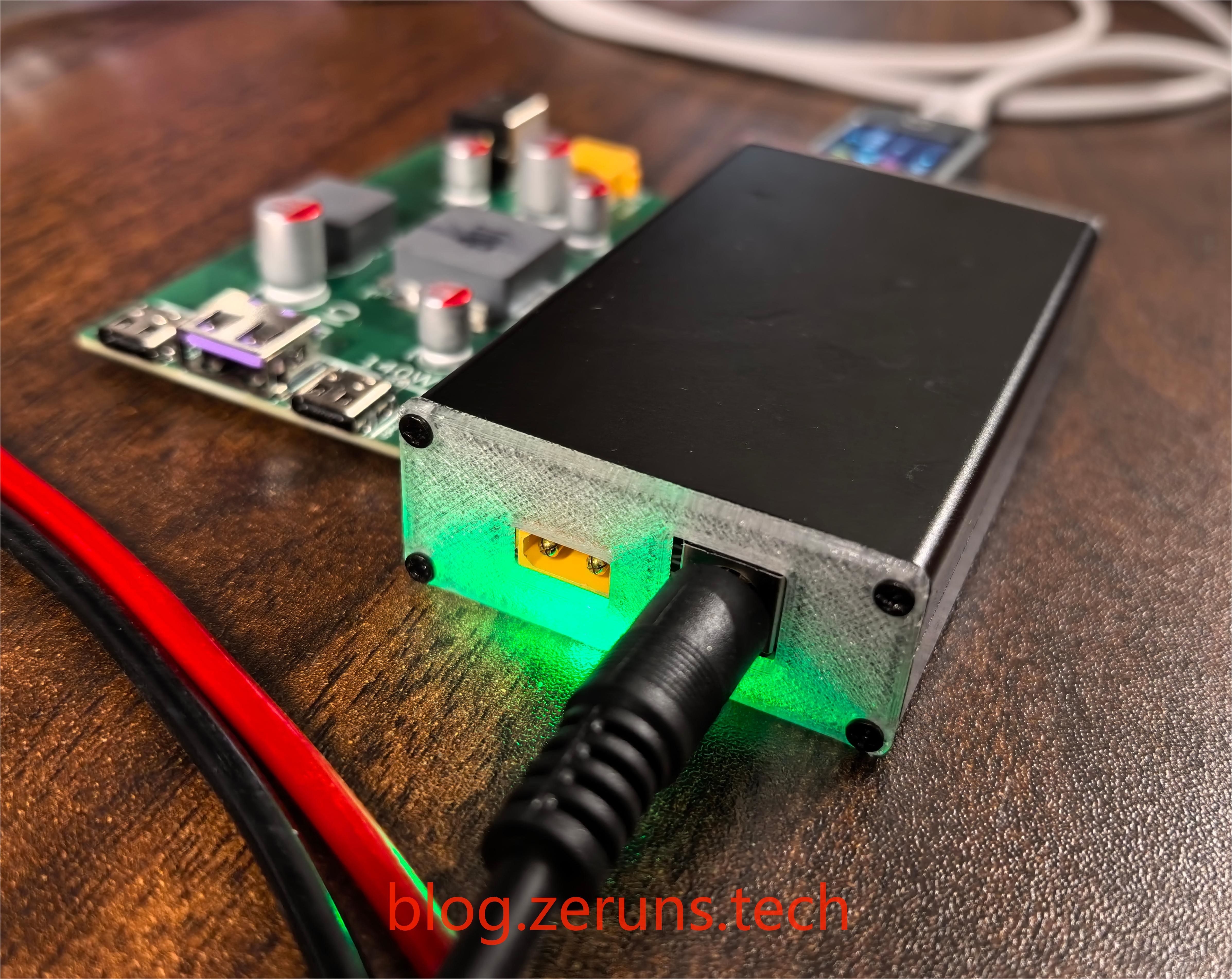
The fast charging module has XT30 and DC 5.5 input interfaces (the two input interfaces cannot be used simultaneously; they are connected in parallel!).
Module input voltage range: 8.2~31V
. Port C1 is for buck-boost, the input voltage can be lower than the output voltage; ports C2 and A are for buck, the output voltage can only be lower than the input voltage!
I bought 8 IP6557 chips and soldered them all on. 4 of them were faulty (with various symptoms), only 4 were good. I don't know if it's a chip quality/quality control issue or a problem with my soldering (the heating plate temperature is set to 230 degrees Celsius, and there are no cold solder joints). All IP6538 chips are good and have never had any problems. Both chips were bought from the same store.
I've made several finished products; if you need to buy finished products, you can join the group to ask.
Parameters and Introduction:
Port C1 (IP6557):
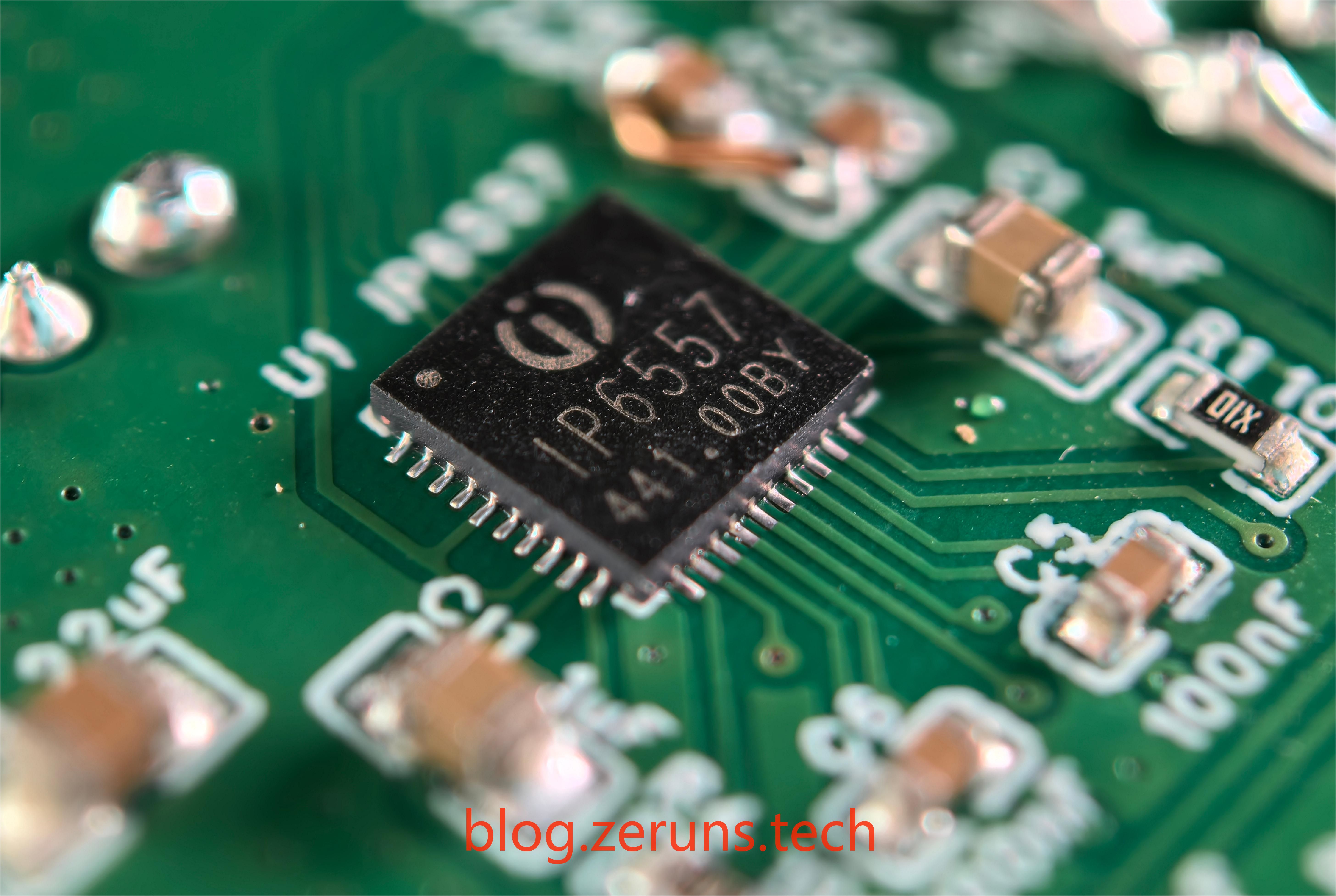
The first Type-C power chip is INJOINIC's IP6557-C, with a maximum output power of 140W and a maximum output of 28V/5A (actual maximum can reach 6A).
Input voltage range: 5~31V.
This chip is a buck-boost converter, so the output voltage can be higher than the input voltage.
Supported fast charging protocols include:
PD3.1/PPS/ERP28V
BC1.2 and APPLE
QC2.0/QC3.0/QC3+/QC4+/QC5
FCP and HSCP
AFC.
MTK
UFCS (Unified Fast Charging)
supports 5V, 9V, 12V, 15V, 20V, and 28V voltage output.
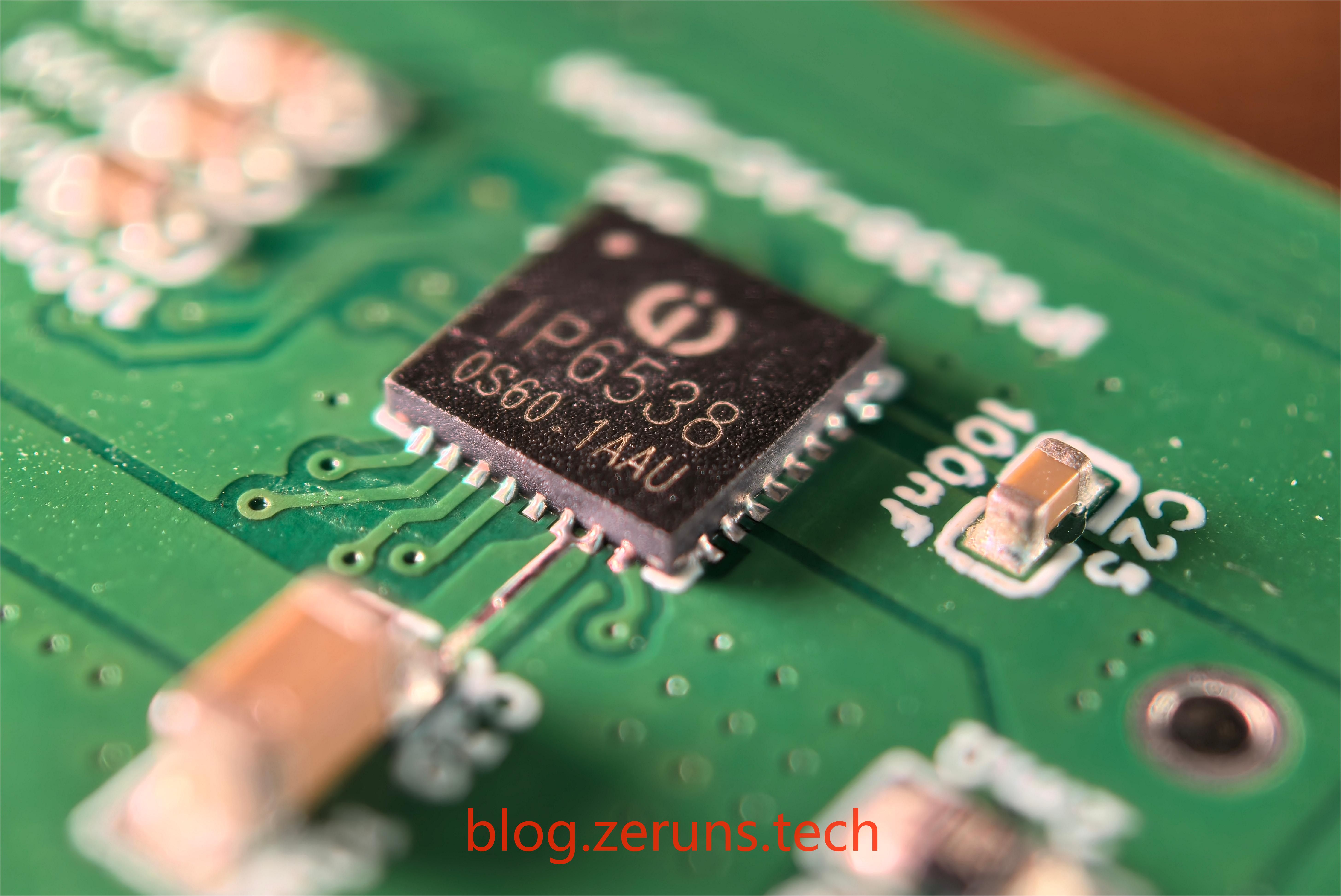
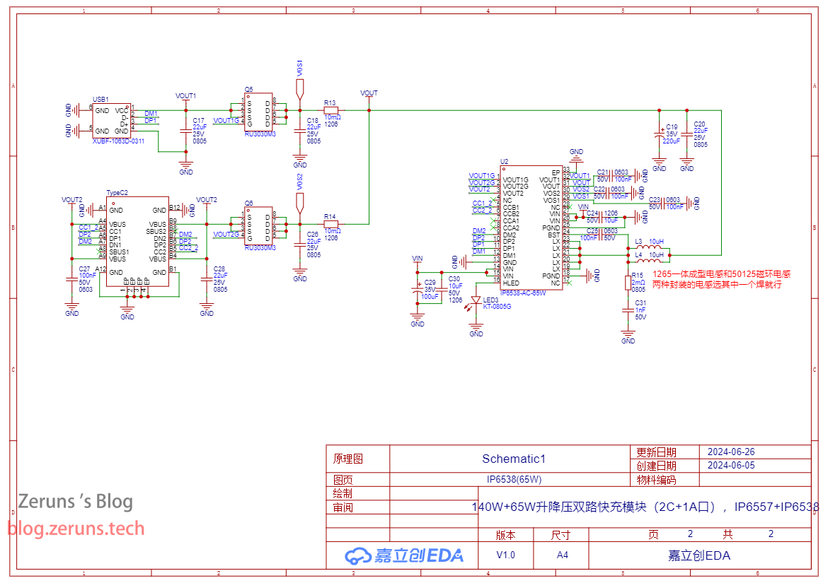
PPS supports 3.3V-21V, 10mV/step voltage output. The power chip for the second Type-C and Type-A ports
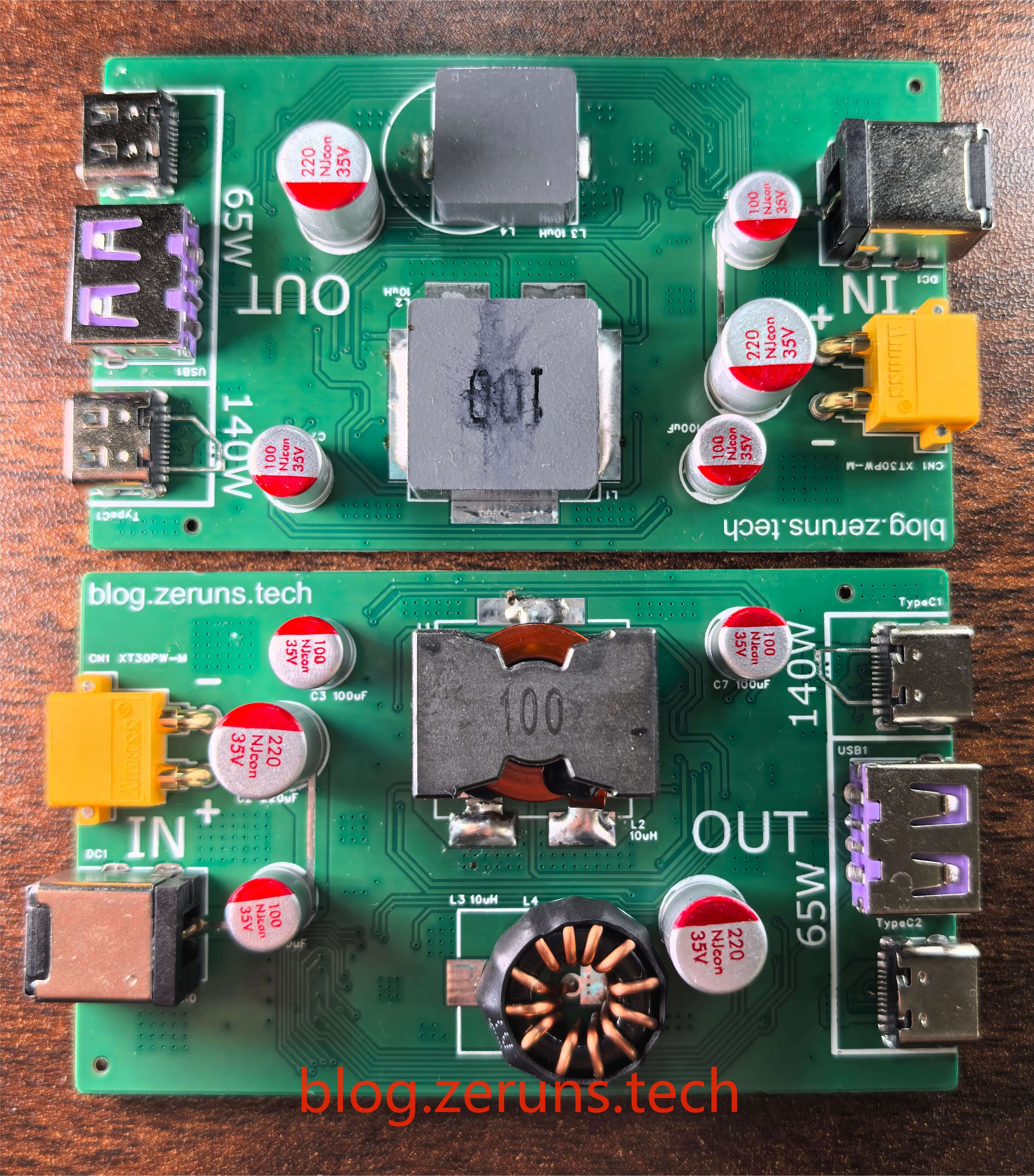
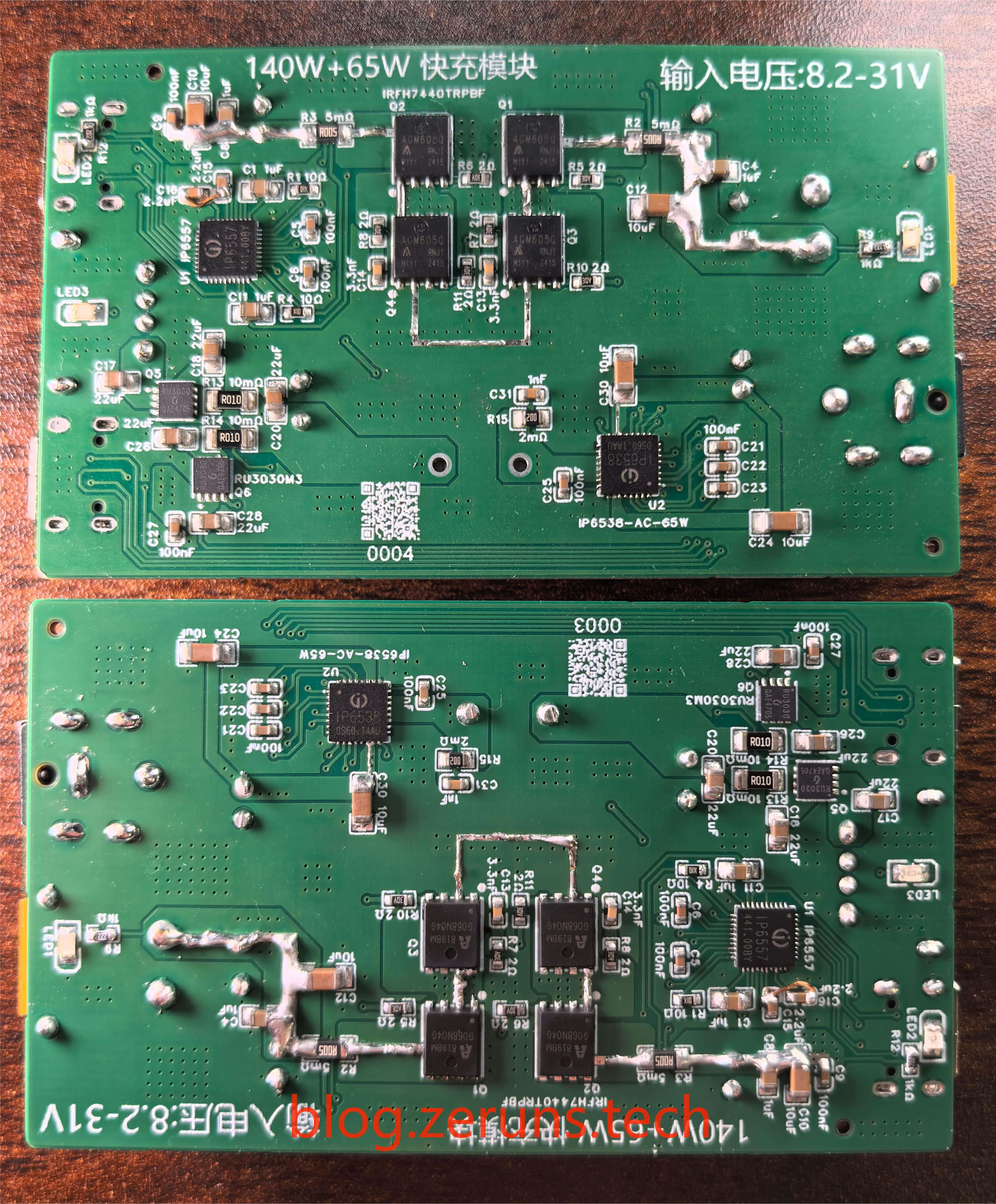
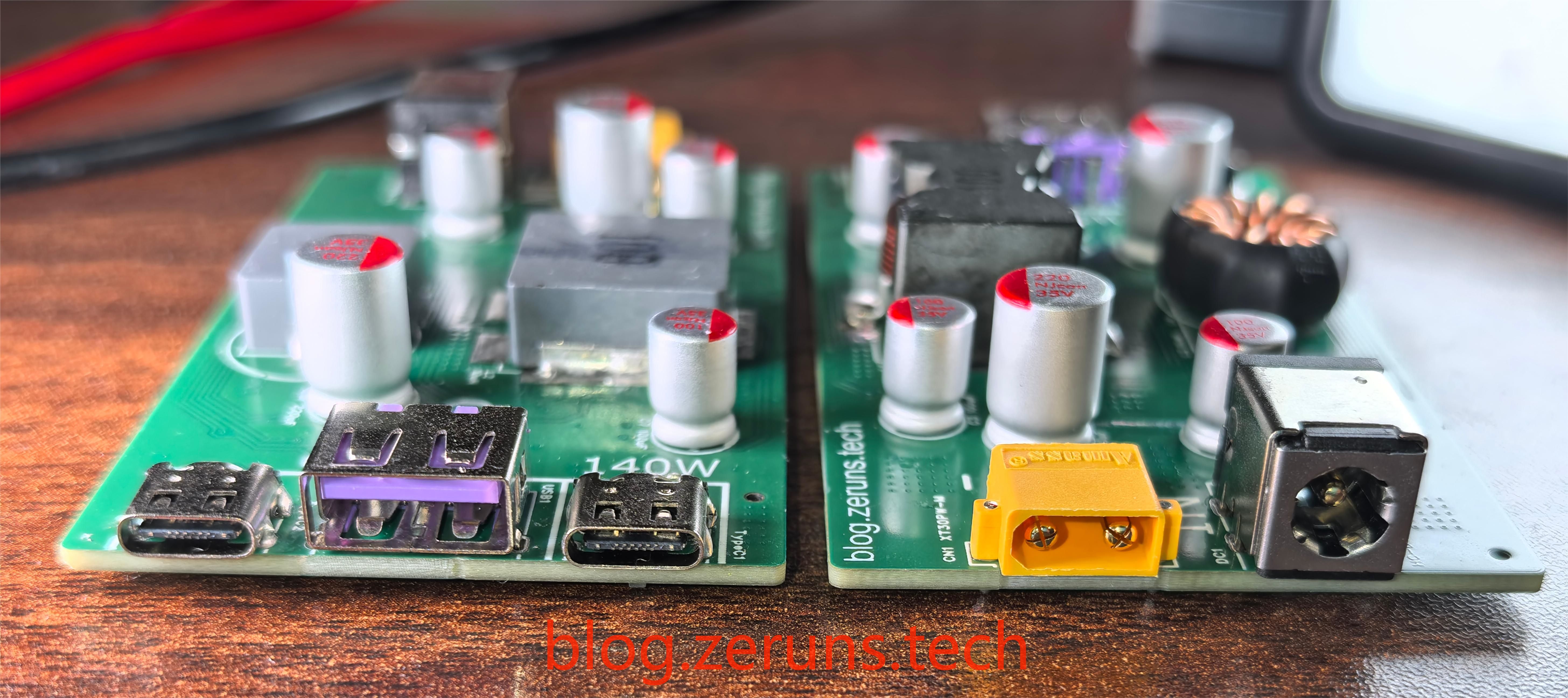
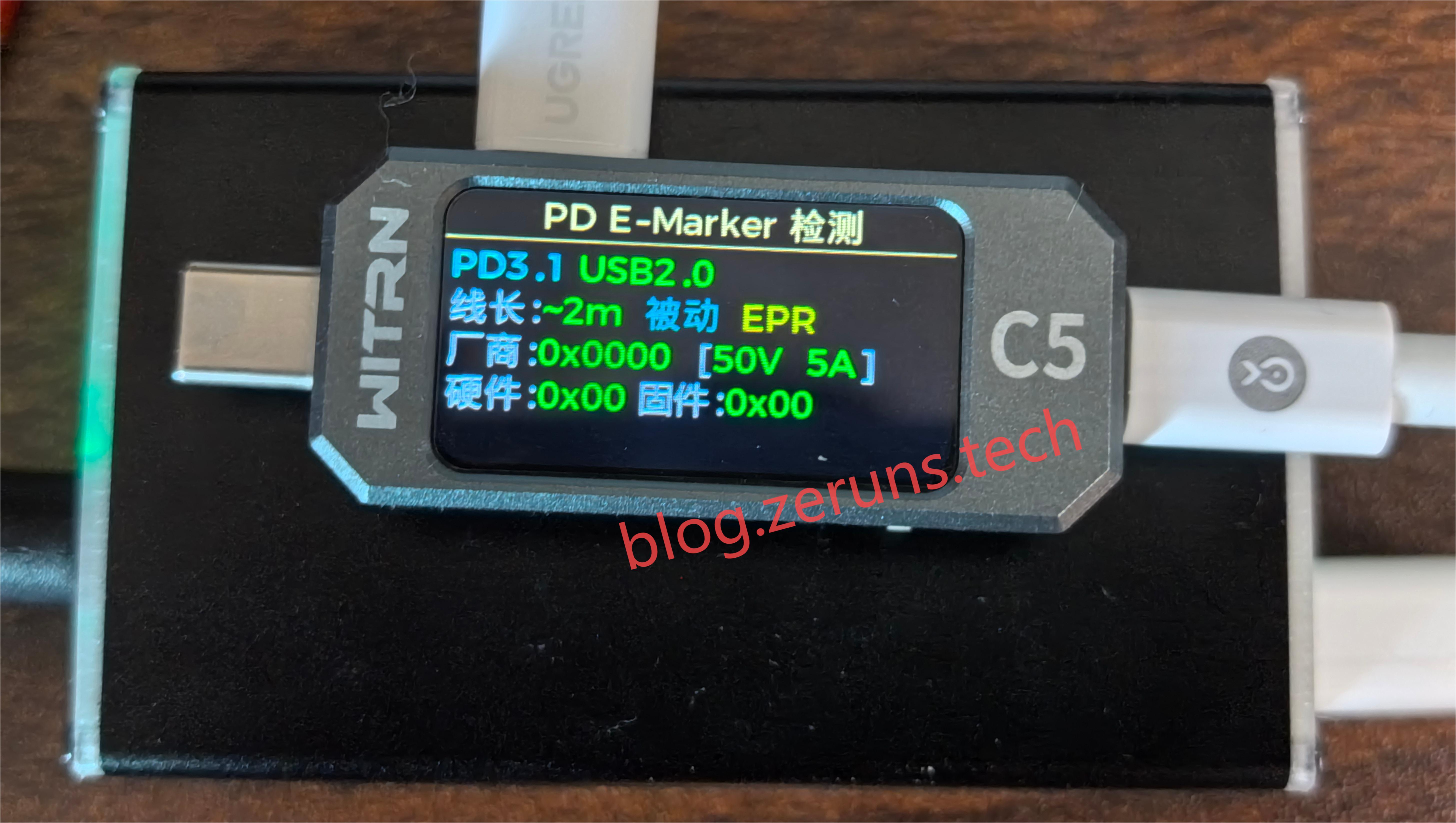
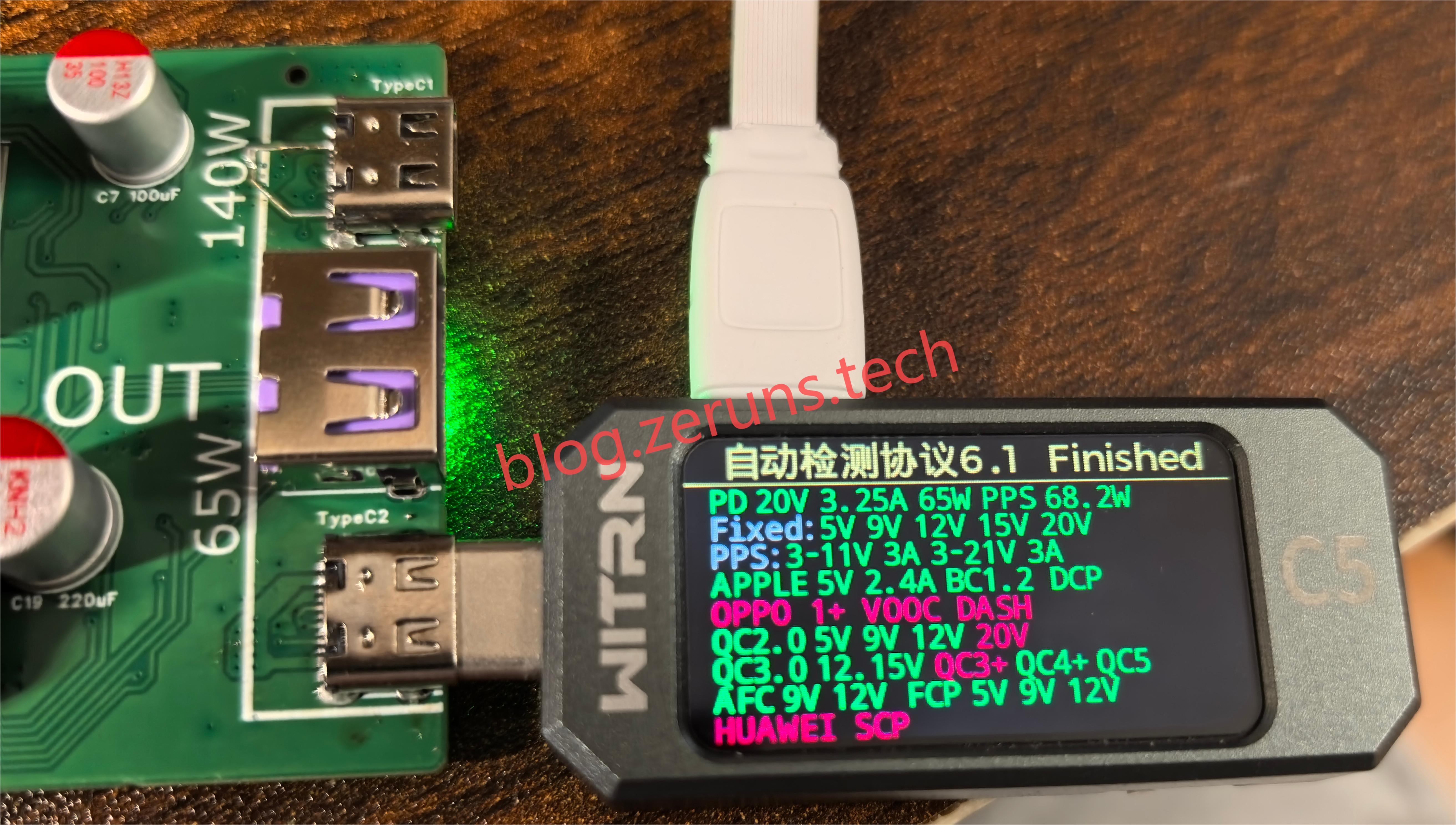
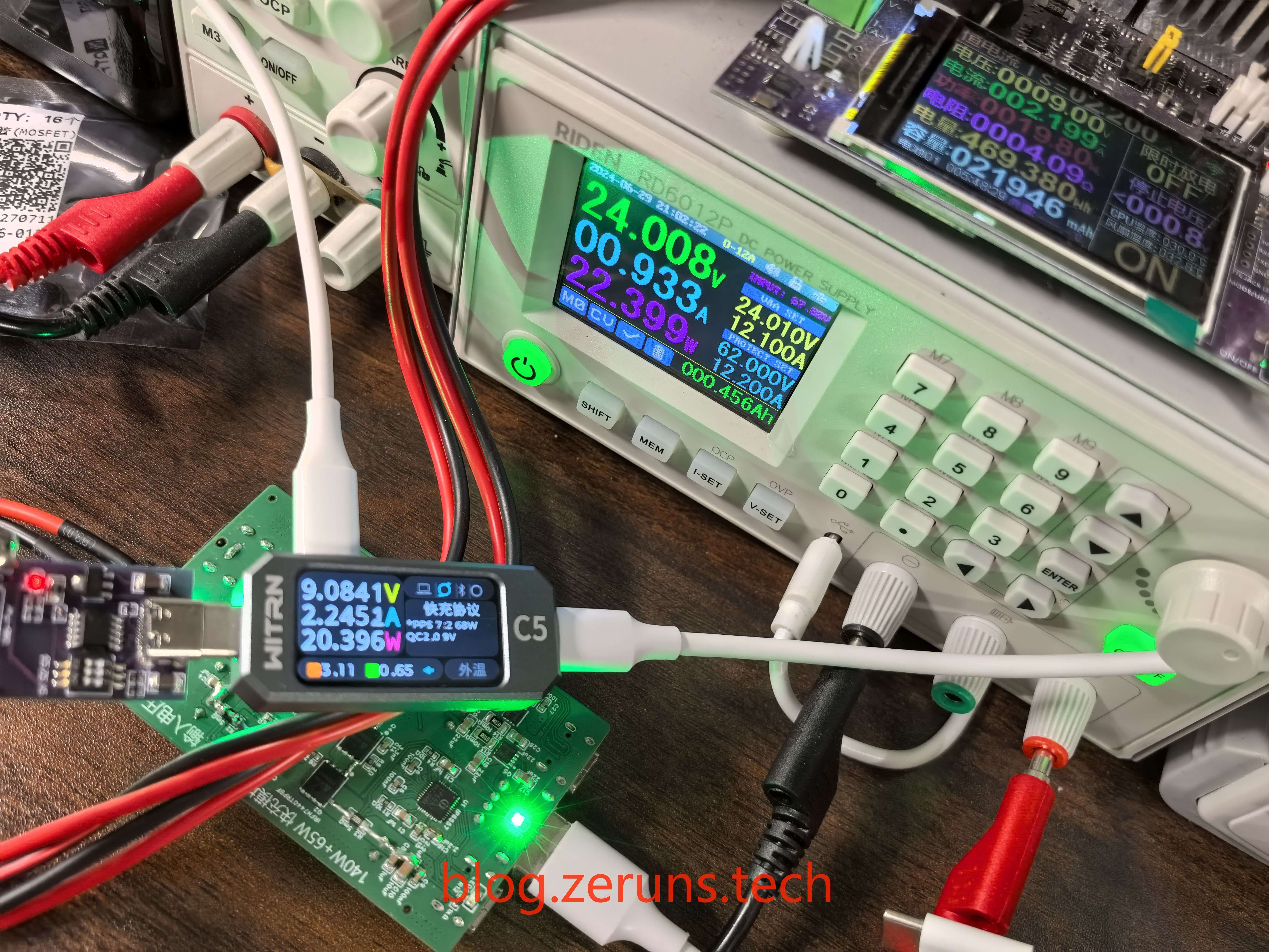
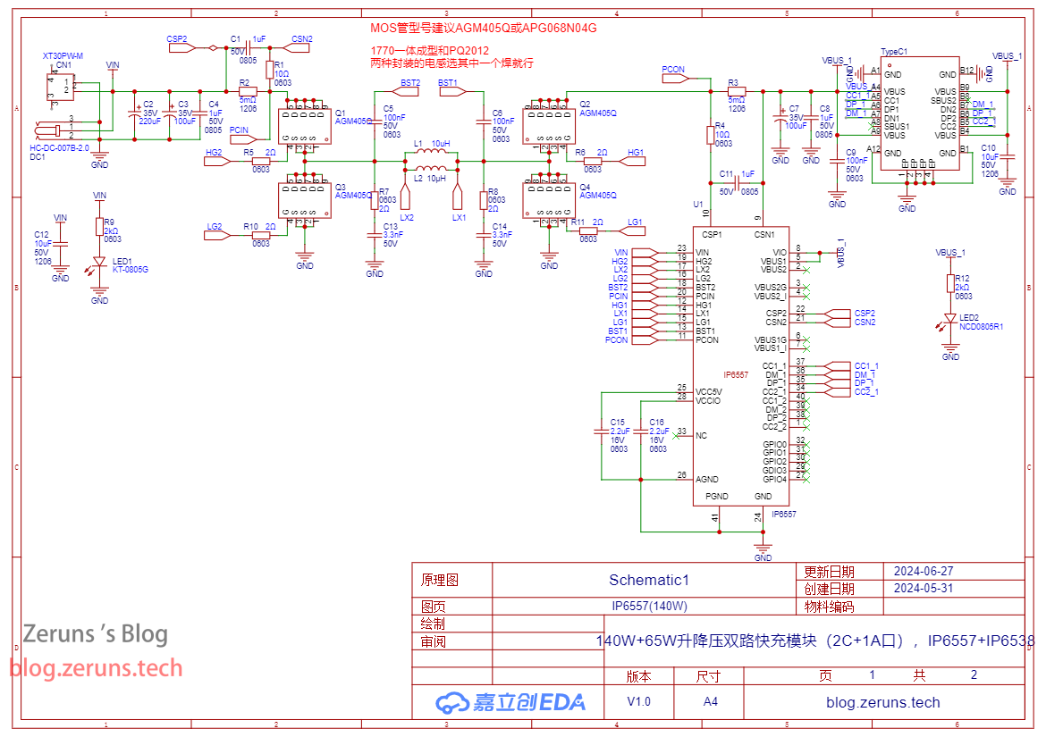
(C2 and A1, IP6538) is IP6538-AC-65W. When using a single Type-C port, the maximum output is 20V/3.25A, with a maximum power of 65W. When both ports are used simultaneously, both output 5V, for a total power of 5V/4.8A. Input voltage range: 8.2V~32V (both chips share an input port, so we'll assume a maximum of 31V). This chip is a step-down converter, so the output voltage will not exceed the input voltage. To output 65W, the input voltage must be above 21V. Note: The IP6538 comes in 45W and 65W versions; the version without the -65W suffix is the 45W version! (The datasheet below is for the 45W version; the 65W version's datasheet is unavailable.) Supported fast charging protocols include: PD2.0 / PD3.0 (PPS), Type-A port does not support PD protocol BC1.2, Apple, Samsung protocols QC2.0 and QC3.0 , MTK PE+1.1 and MTK PE+2.0, Huawei fast charging protocol FCP / SCP, Samsung fast charging protocol AFC , Spreadtrum fast charging protocol SFCP, OPPO fast charging protocol VOOC / Super VOOC (the 65W version chip seems to not support the OPPO fast charging protocol; the 45W version has not been tested, and it's possible that an original cable is required to trigger it). Supports 5V, 9V, 12V, 15V, and 20V voltage output. PPS supports 3.3V~11V, 20mV/step voltage output. The actual circuit board is shown in the front and back images. The flying wires in the image below are due to a misdrawing of the schematic in the Injoinic official datasheet, where the intersections of lines weren't represented by dots. This caused the connection to be missing, necessitating the use of flying wires. The schematic and PCB I've released have fixed this issue. The aluminum alloy casing on the side of the circuit board is a pre-purchased product, while the front and back covers are 3D printed by myself. Tuozhu P1SC 3D printer unboxing experience: https://blog.zeruns.tech/archives/770.html Macro images of the soldered IP6557 and IP6538 chips. Instructions & Precautions : 1. To output 28V/5A, a data cable with an E-Marker chip is required, and the PD3.1 protocol must be supported, as shown in the image below. 2. The input current sampling resistor (current sensing resistor) R2 on the board is 5mΩ. The IP6557 chip's input current limit is set to 10A. If the input voltage is 12V, the minimum input current required to output 140W of power is 12A. Exceeding the current limit will cause the output voltage to drop, preventing full power output. The input current sampling resistor R2 can be replaced with a smaller value, such as 2.5mΩ (two 5mΩ resistors can be connected in parallel). This allows for full power output even with a low 12V input. However, this significantly increases the input current, causing the MOSFETs to overheat, requiring proper heat dissipation. The two images below show the current before the resistor was modified, with the input current limited to 10A; the other shows the current after the modification, where the input current can exceed 10A, allowing for a 28V/5A output with a 12V input. Since my adjustable power supply's maximum output current is 12A, which is insufficient, I adjusted the input voltage to 14V. 3. If you choose other MOSFET models, ensure the Ciss parameter is less than 1000pF. This is because the IP6557's switching frequency is 250kHz, and higher switching frequencies place stricter requirements on the MOSFET's input capacitor parameters. Excessive Ciss will affect the MOSFET's turn-on and turn-off times. The protocol support test for port C1 is shown in the following figure:
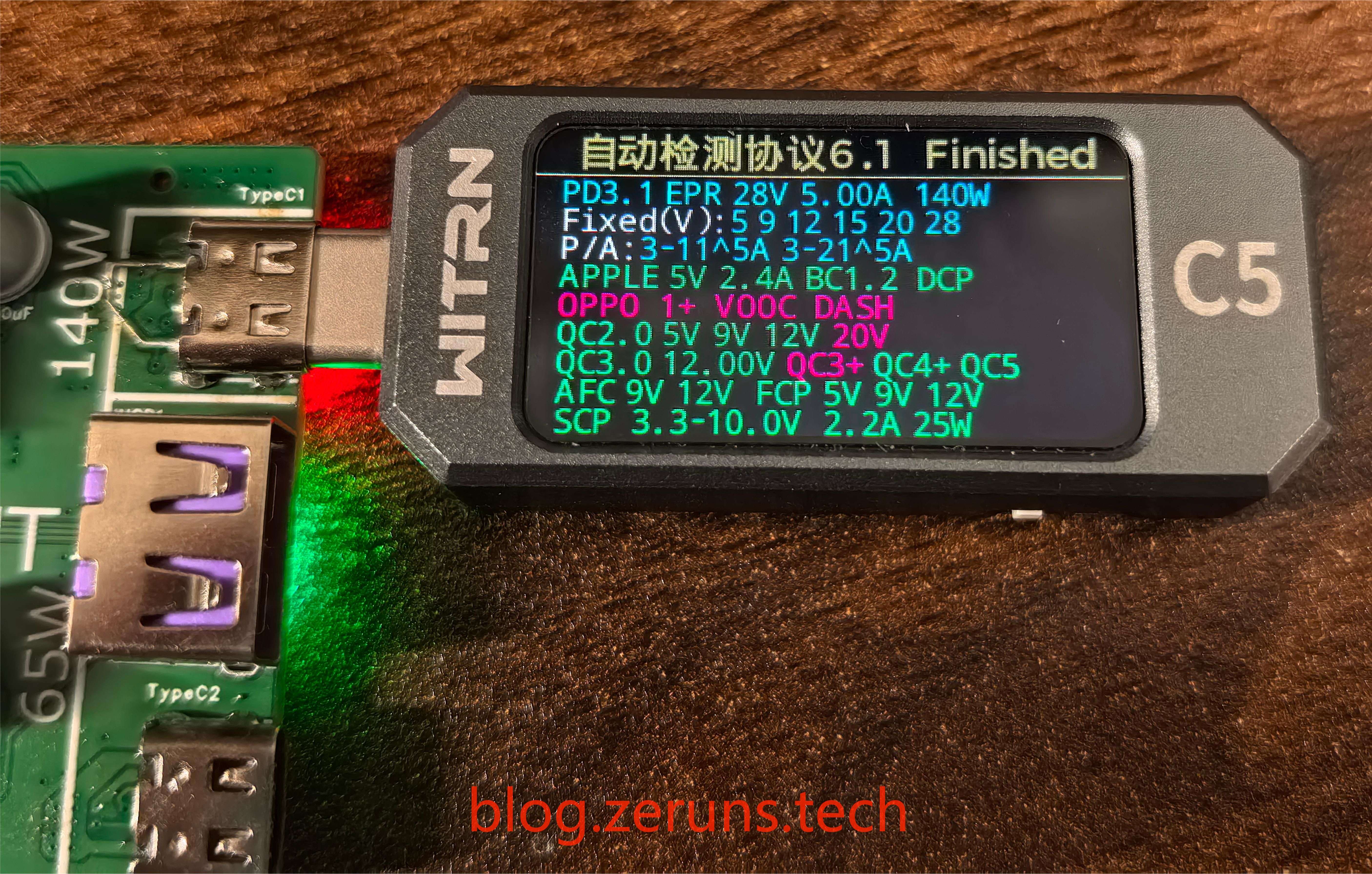
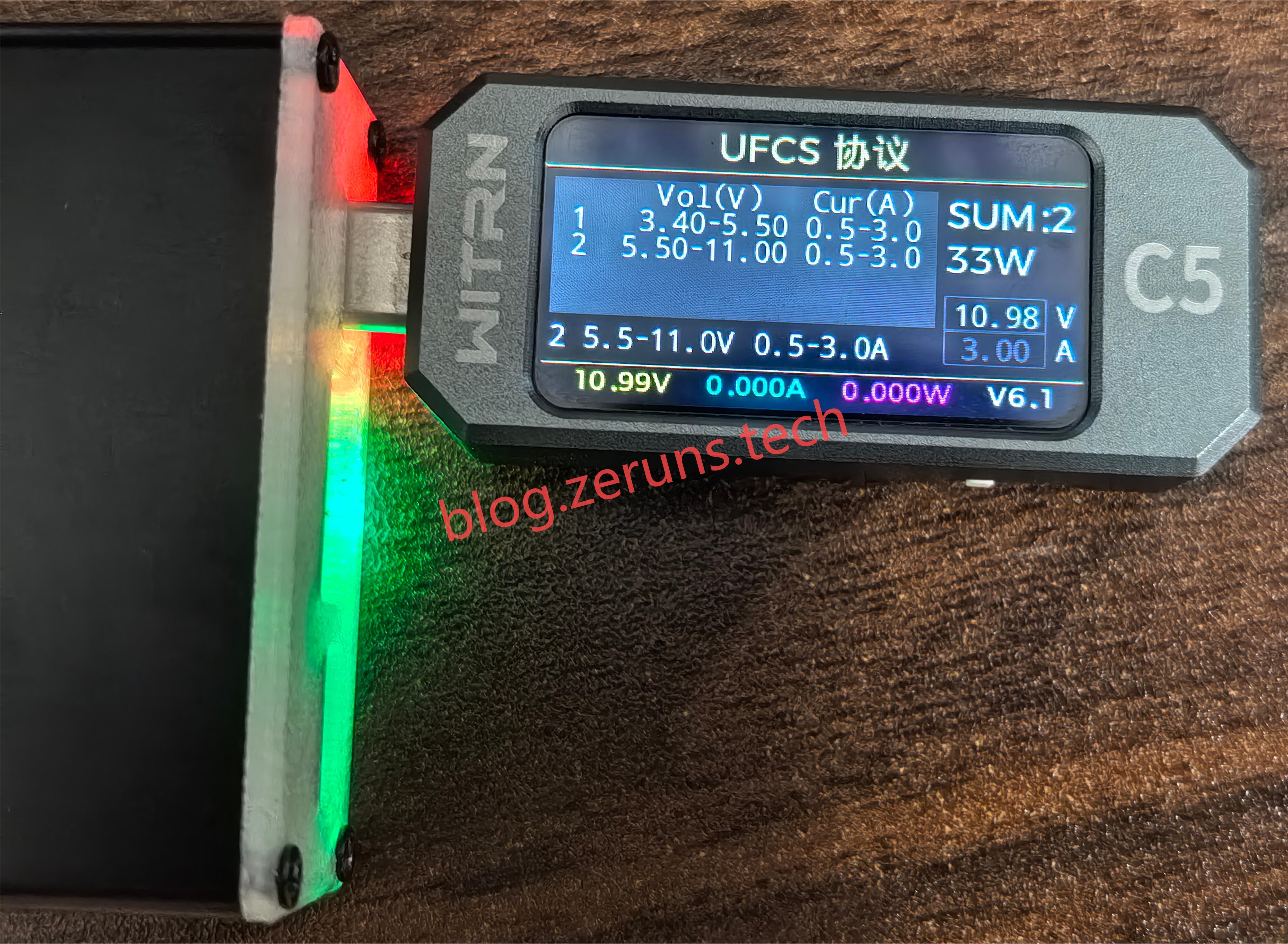
Port C1 also supports the UFCS protocol, but only up to 33W.
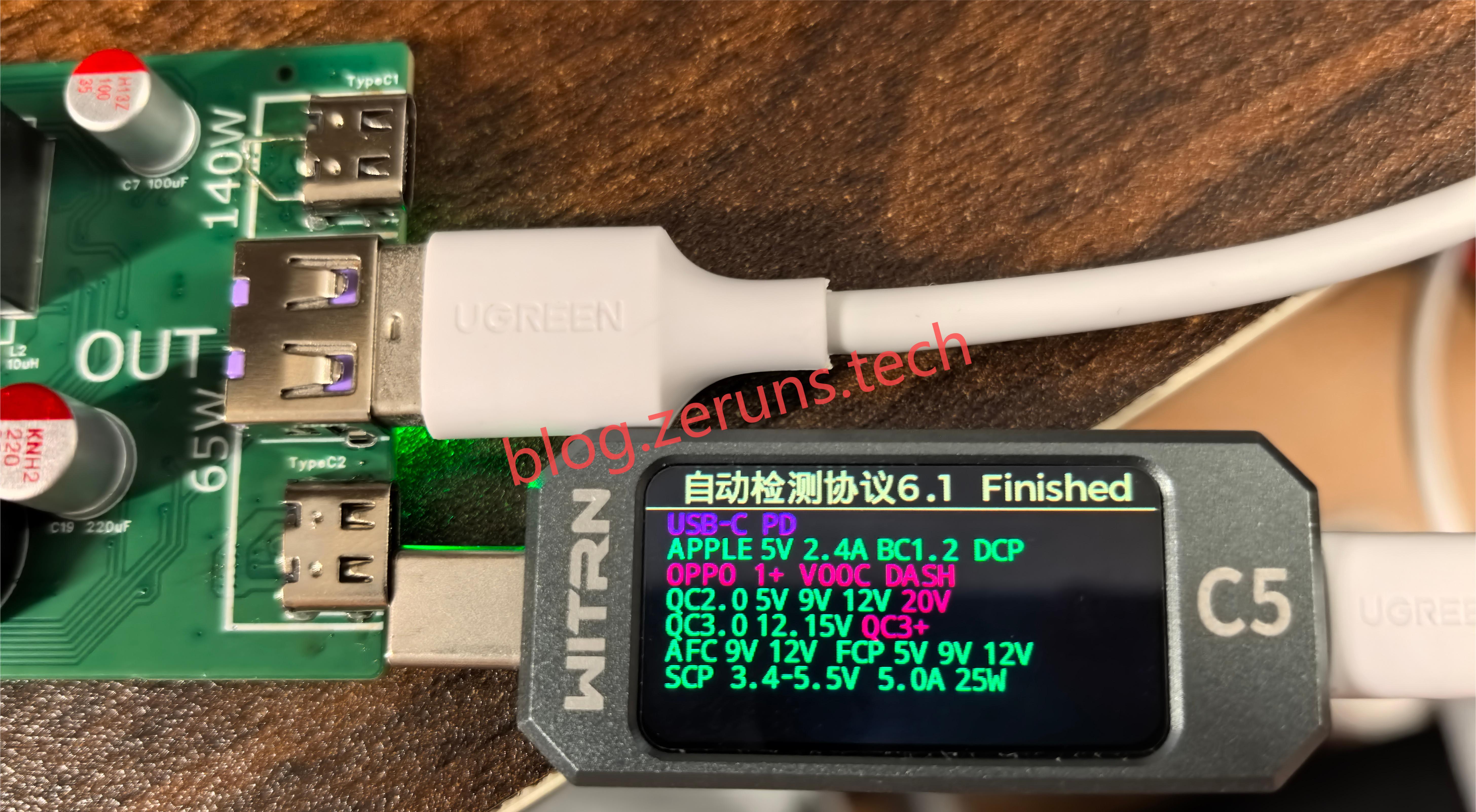
The protocols supported by Port C2 are shown in the following diagram:
The protocols supported by Port A are shown in the following diagram:
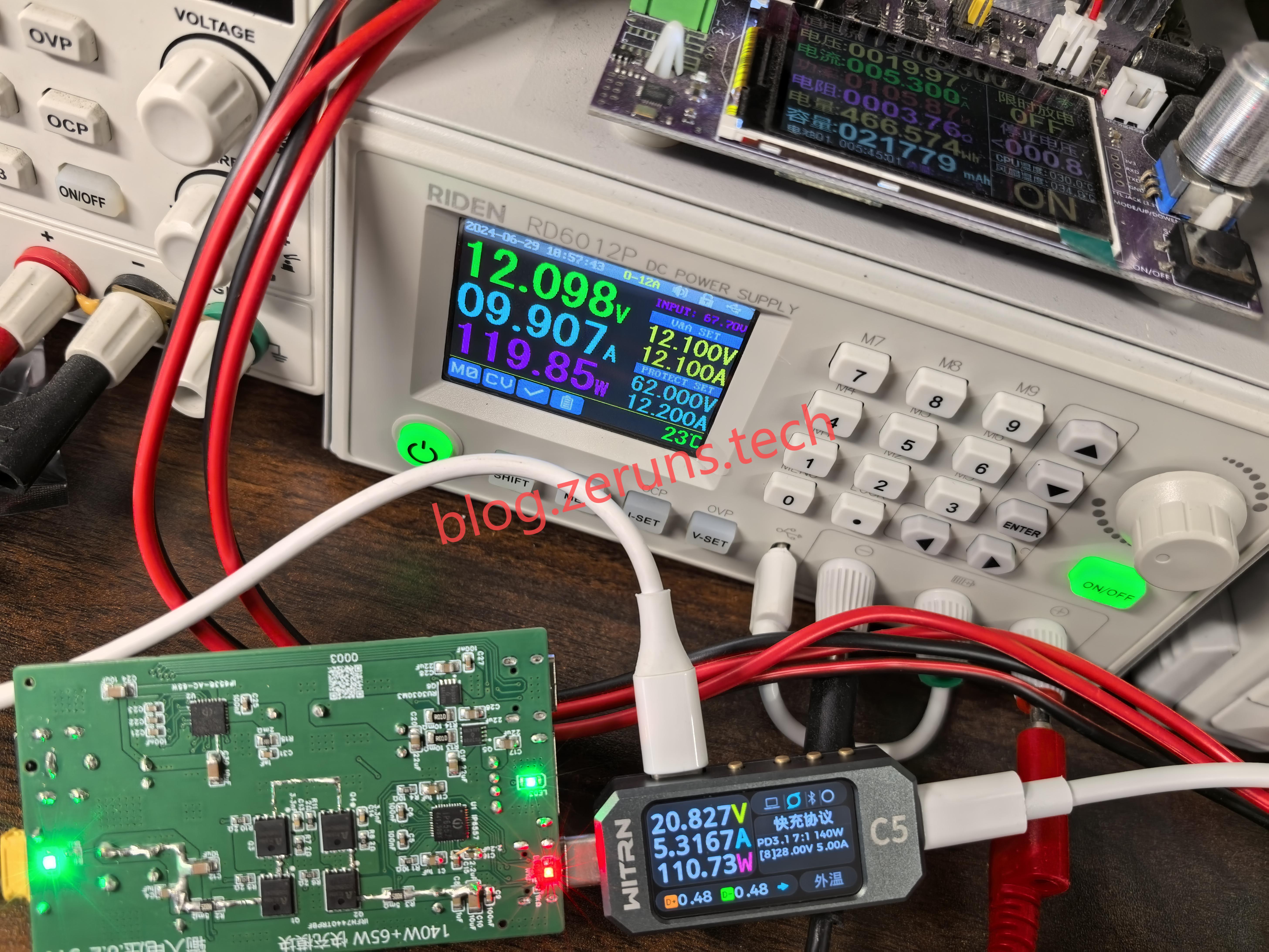
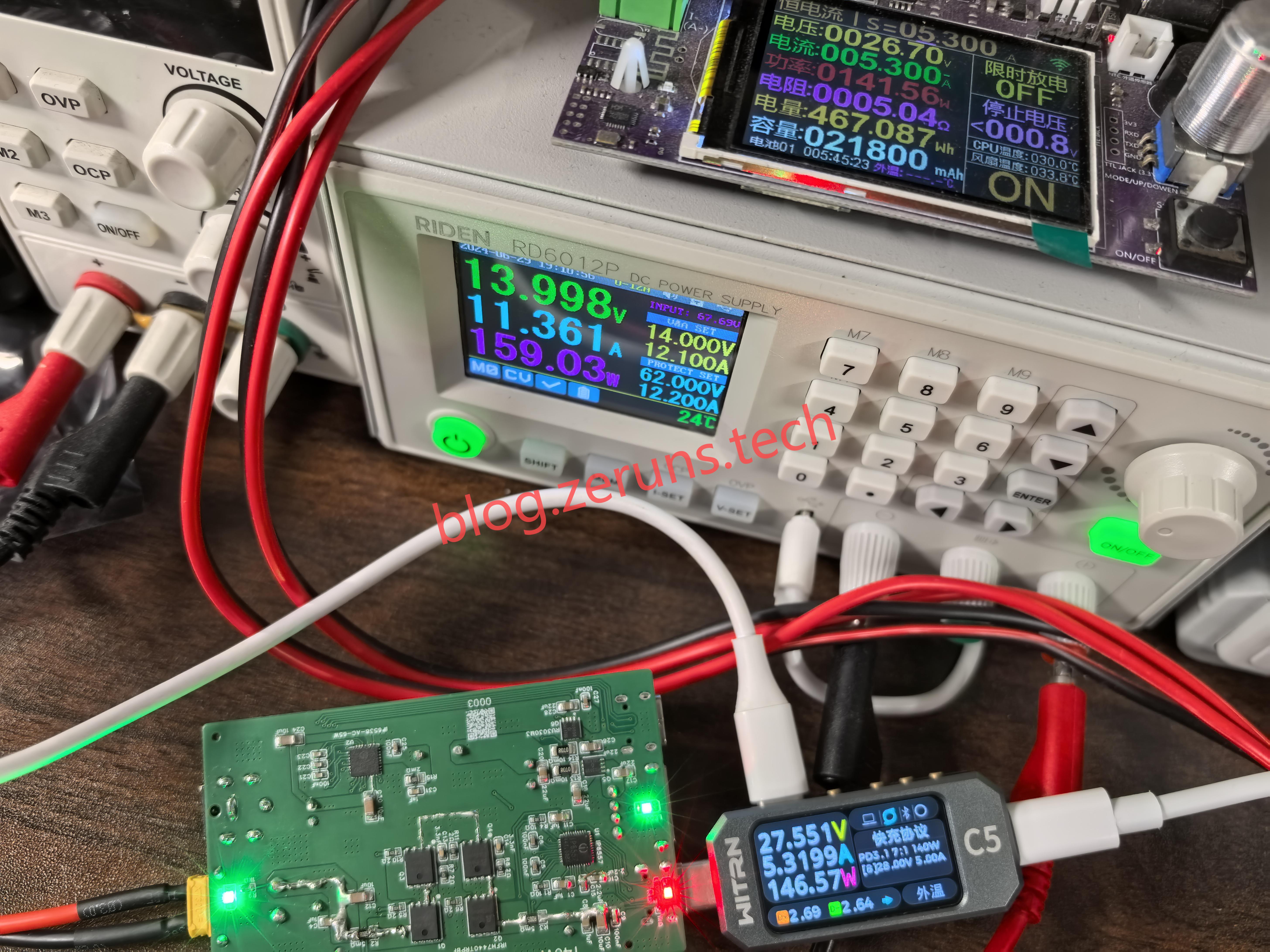
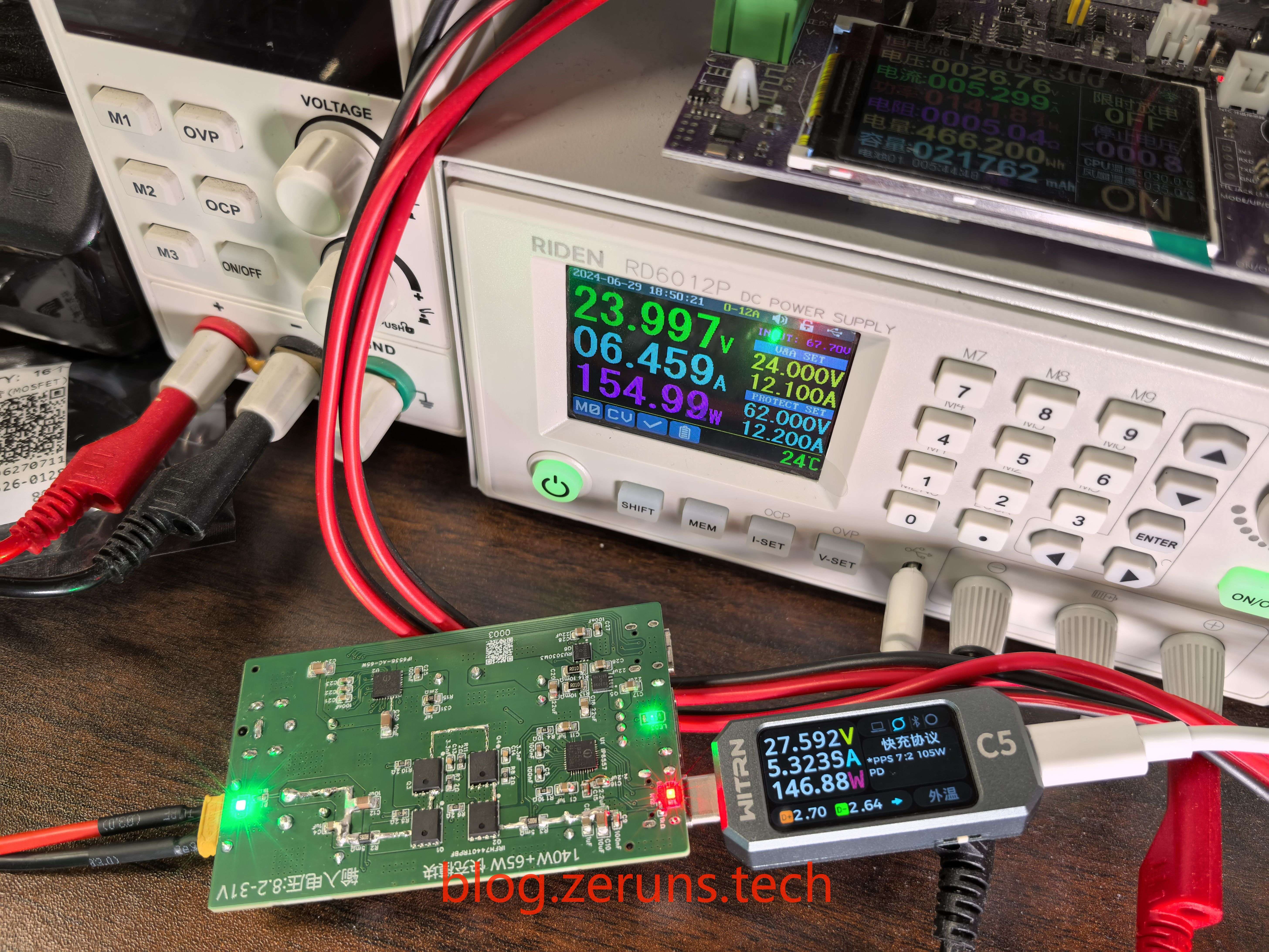
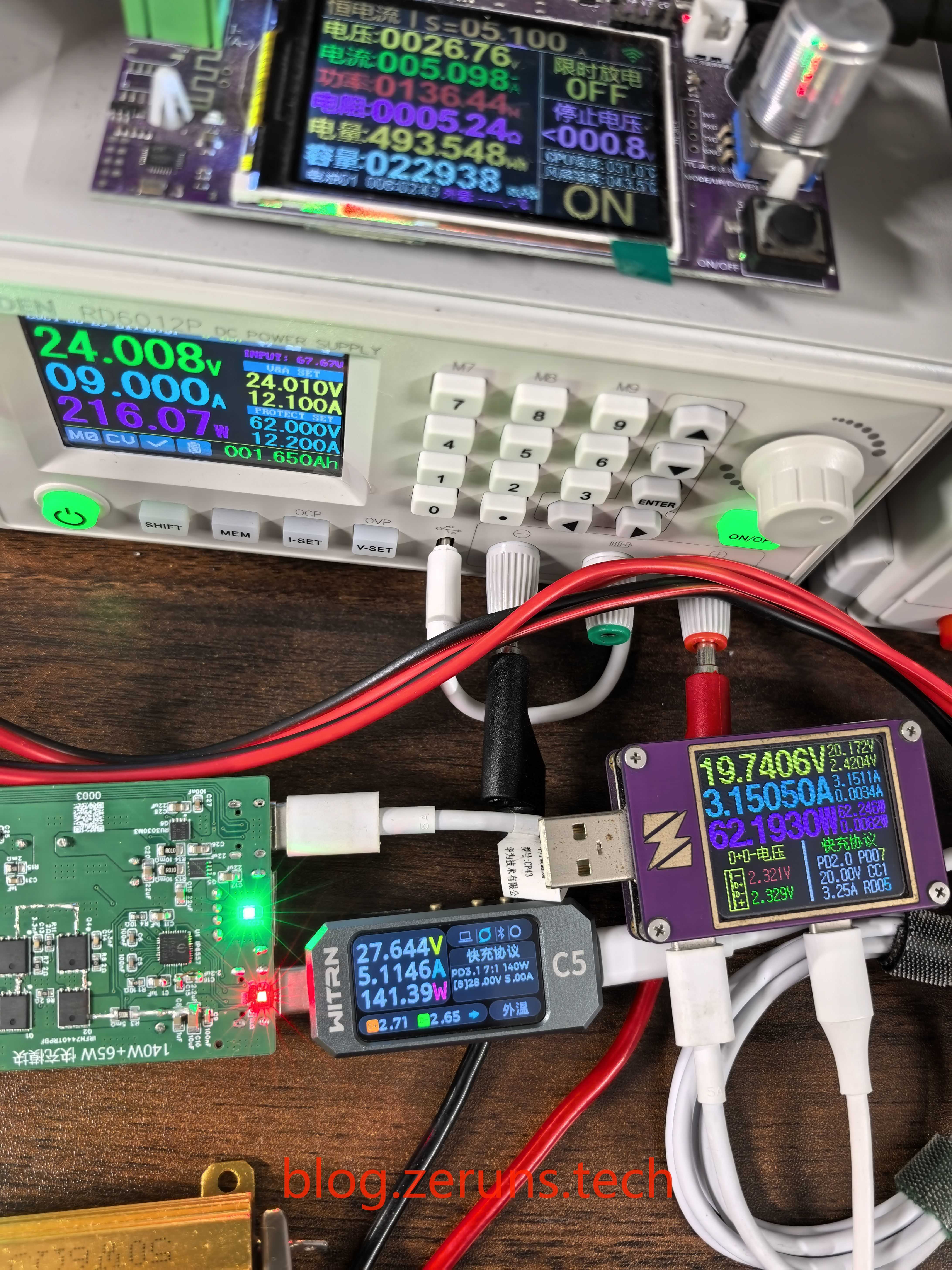
Output load test:
Port C1 test, XT30 interface input 24V, output decoy 28V connected to an electronic load, electronic load set to 5.3A current.
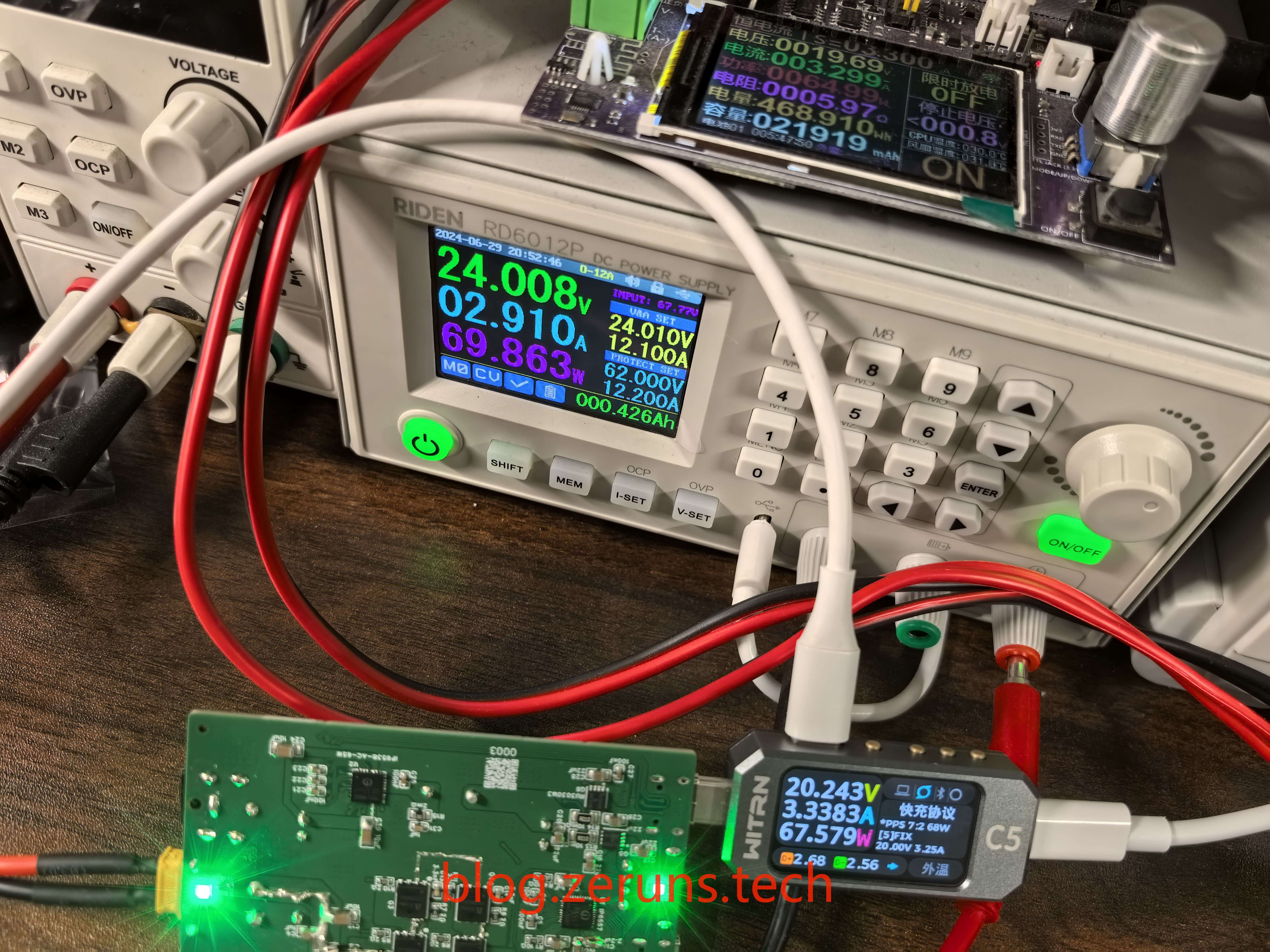
C2 port test,
A port test,
dual-channel full-load output
test. Equipment used for testing:
HP 34401A 6.5-digit multimeter: https://blog.zeruns.tech/archives/772.html;
Ruiden RD6012P digitally controlled adjustable power supply: https://blog.zeruns.tech/archives/740.html
; RIGOL DHO914S oscilloscope: https://blog.zeruns.tech/archives/764.html
; Juwei Electronics load: https://s.click.taobao.com/2sdCaht
; Uni-Trend UTi261M thermal imager unboxing and review: https://blog.zeruns.tech/archives/798.html
; WITRN C5 meter (USB voltmeter/current meter/CC meter): https://s.click.taobao.com/Sy2Daht.
Conversion efficiency test:
The efficiency was tested under several different input and output voltages, connected to C1 and C2 ports respectively.
The IP6557
has a maximum conversion efficiency of 95.468%.
Input Voltage (V)
Input Current (A) Input Power (
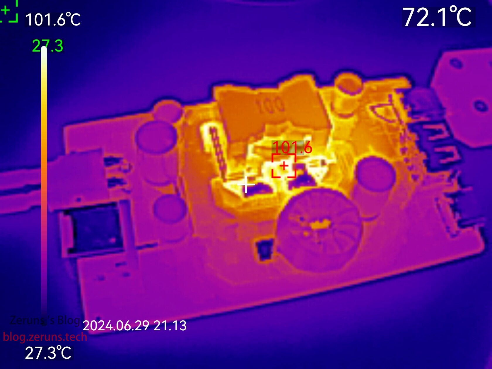
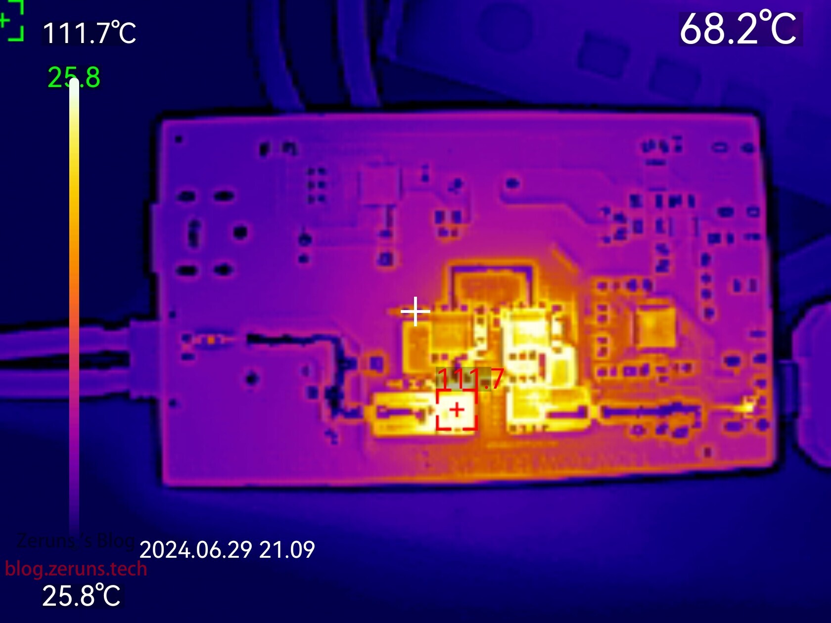
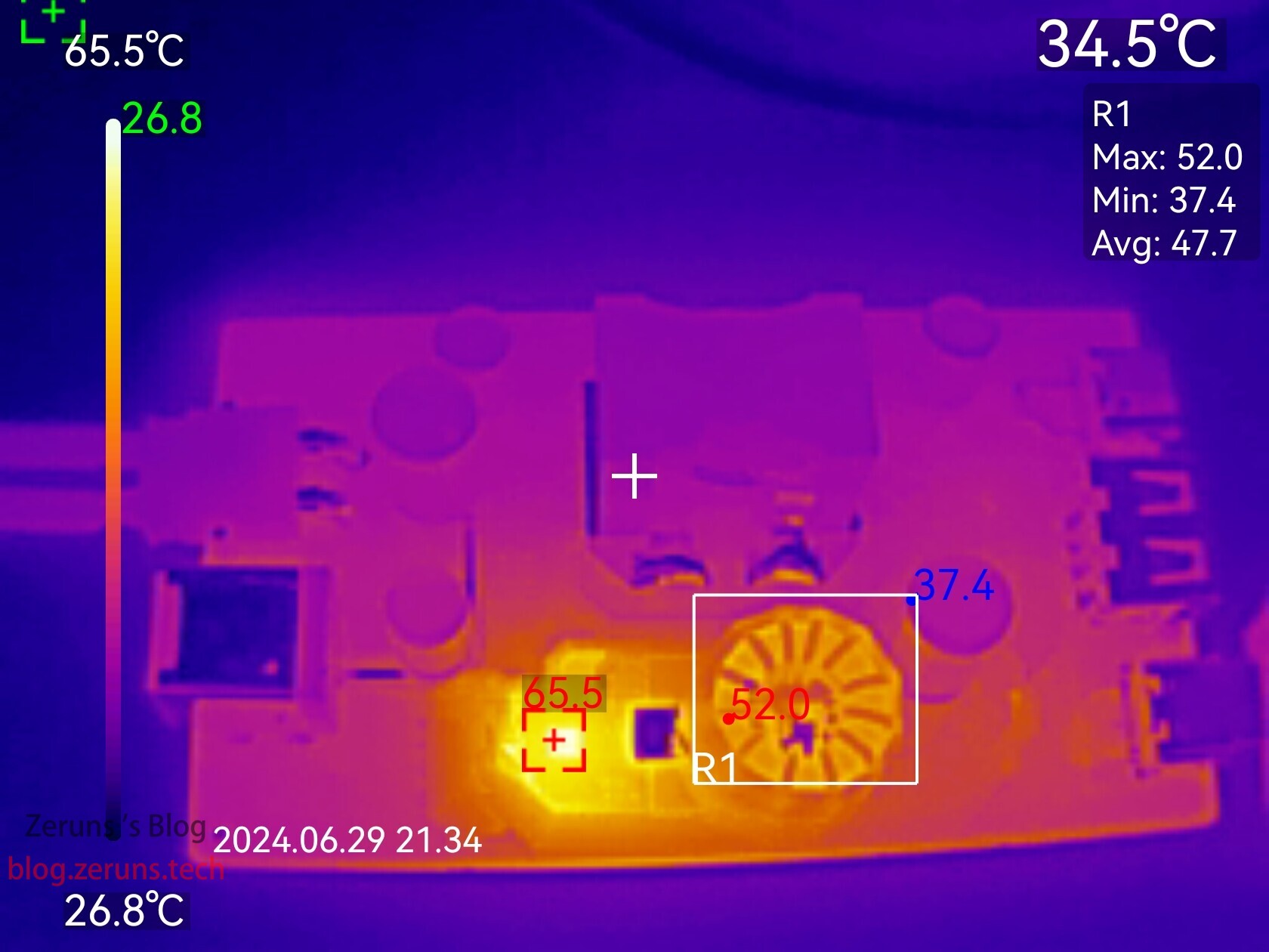
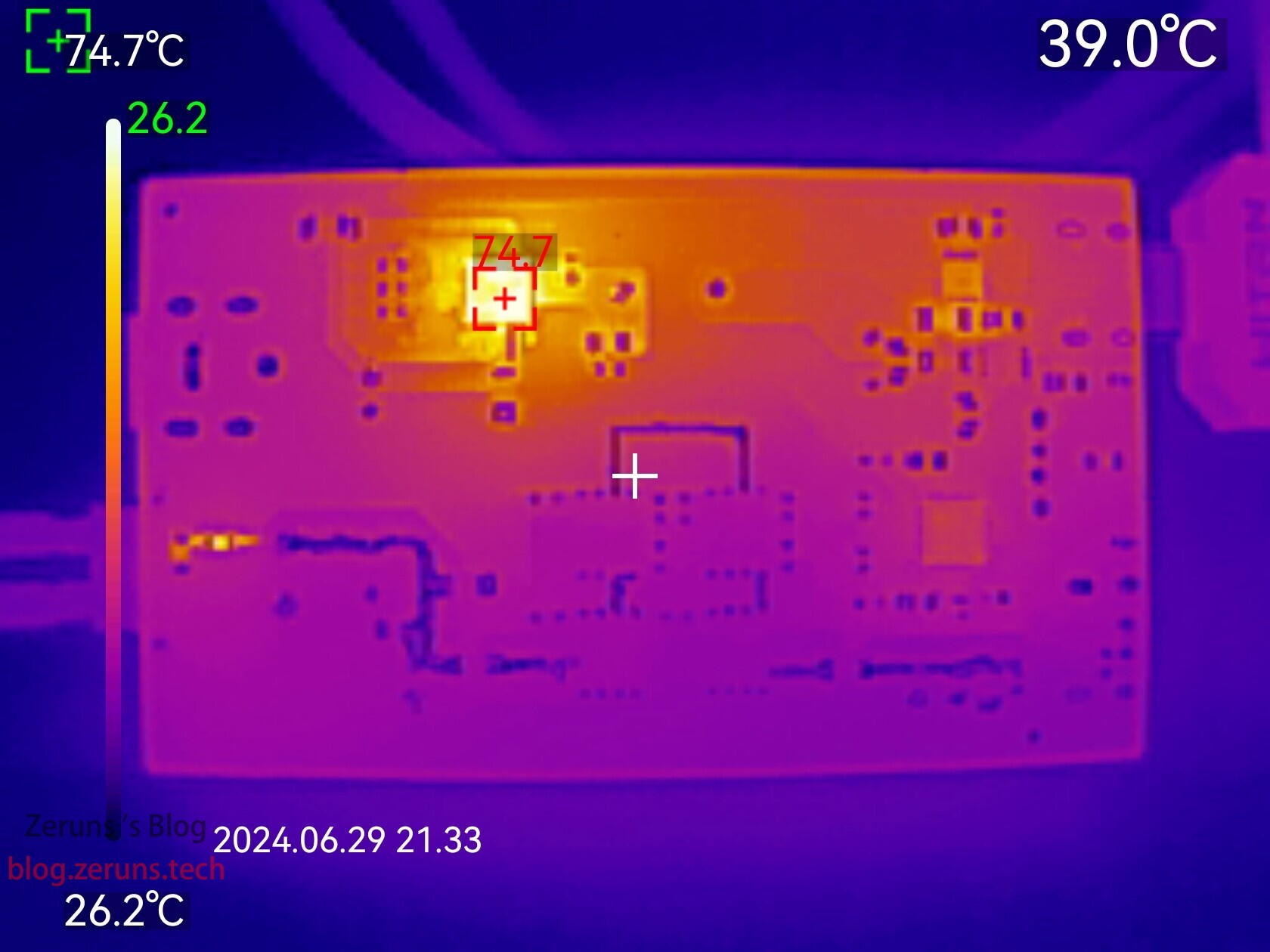
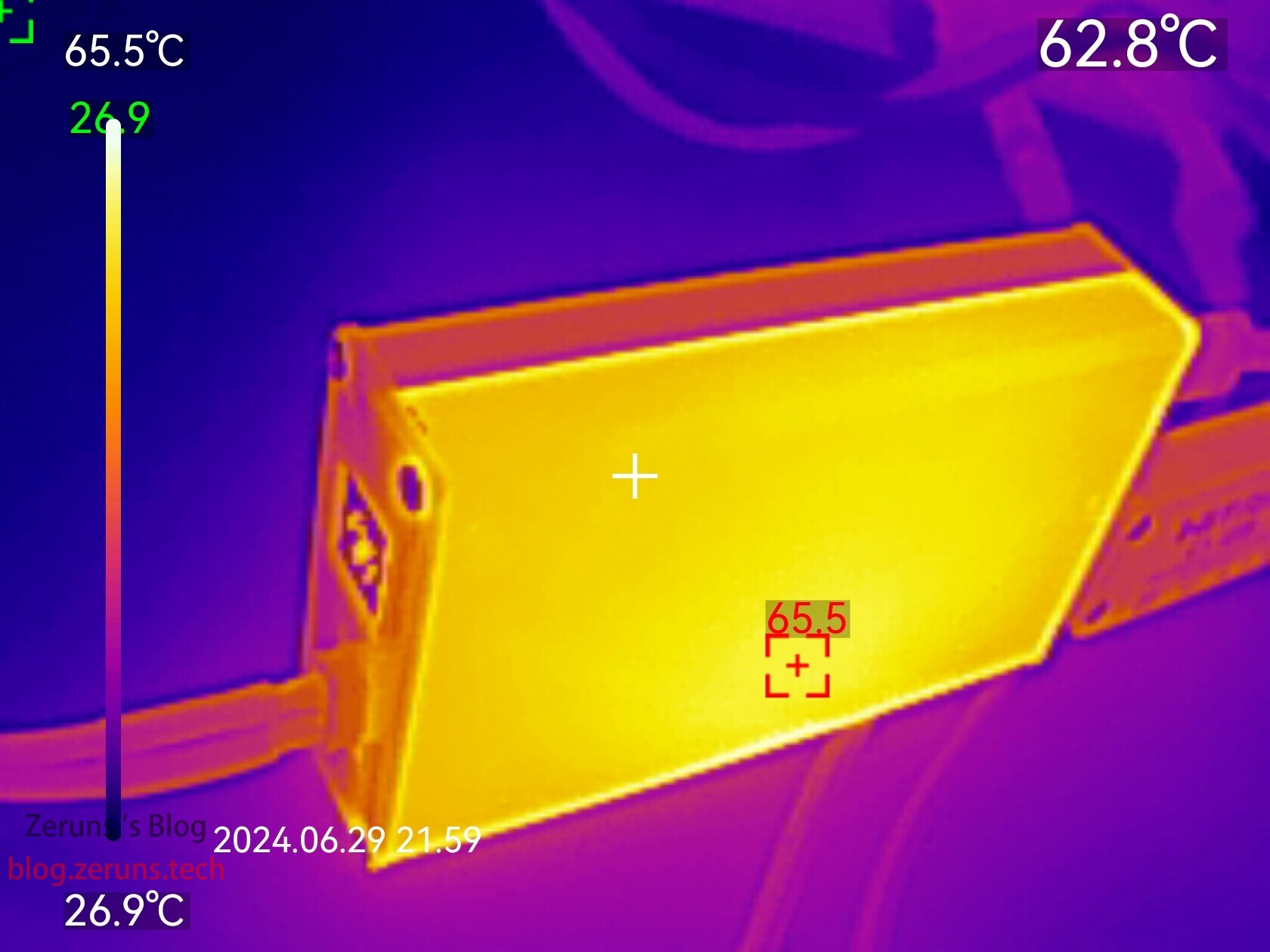
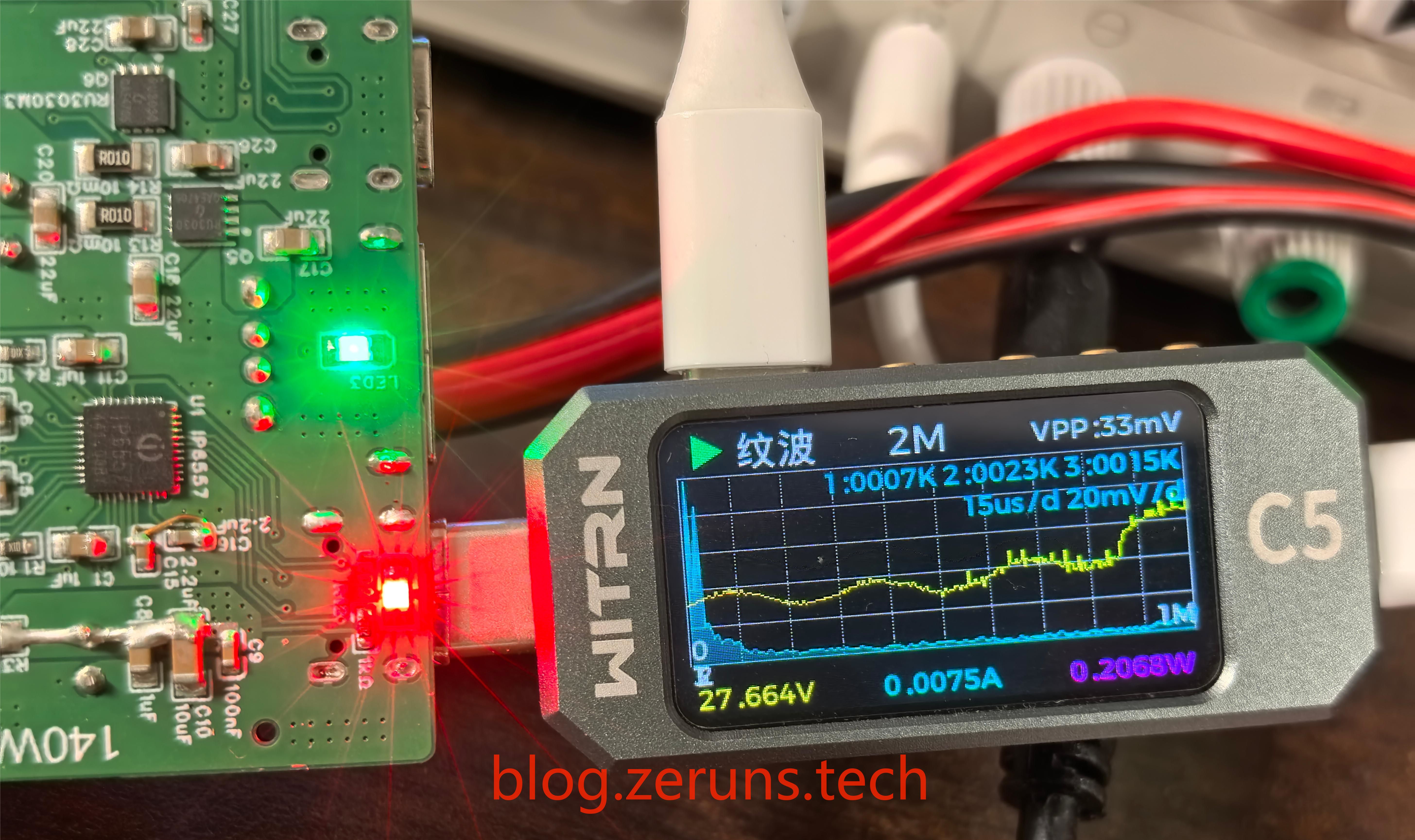
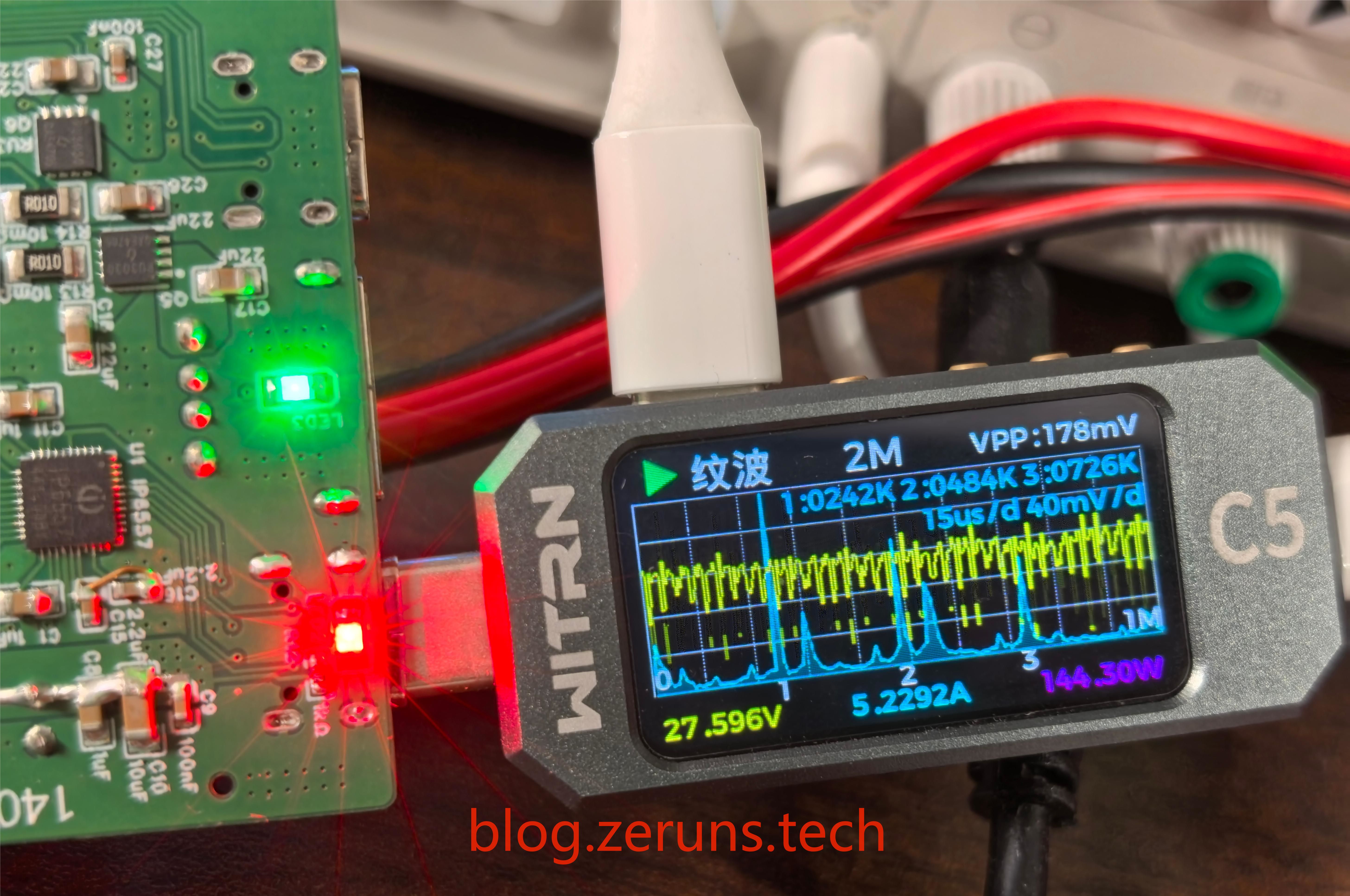
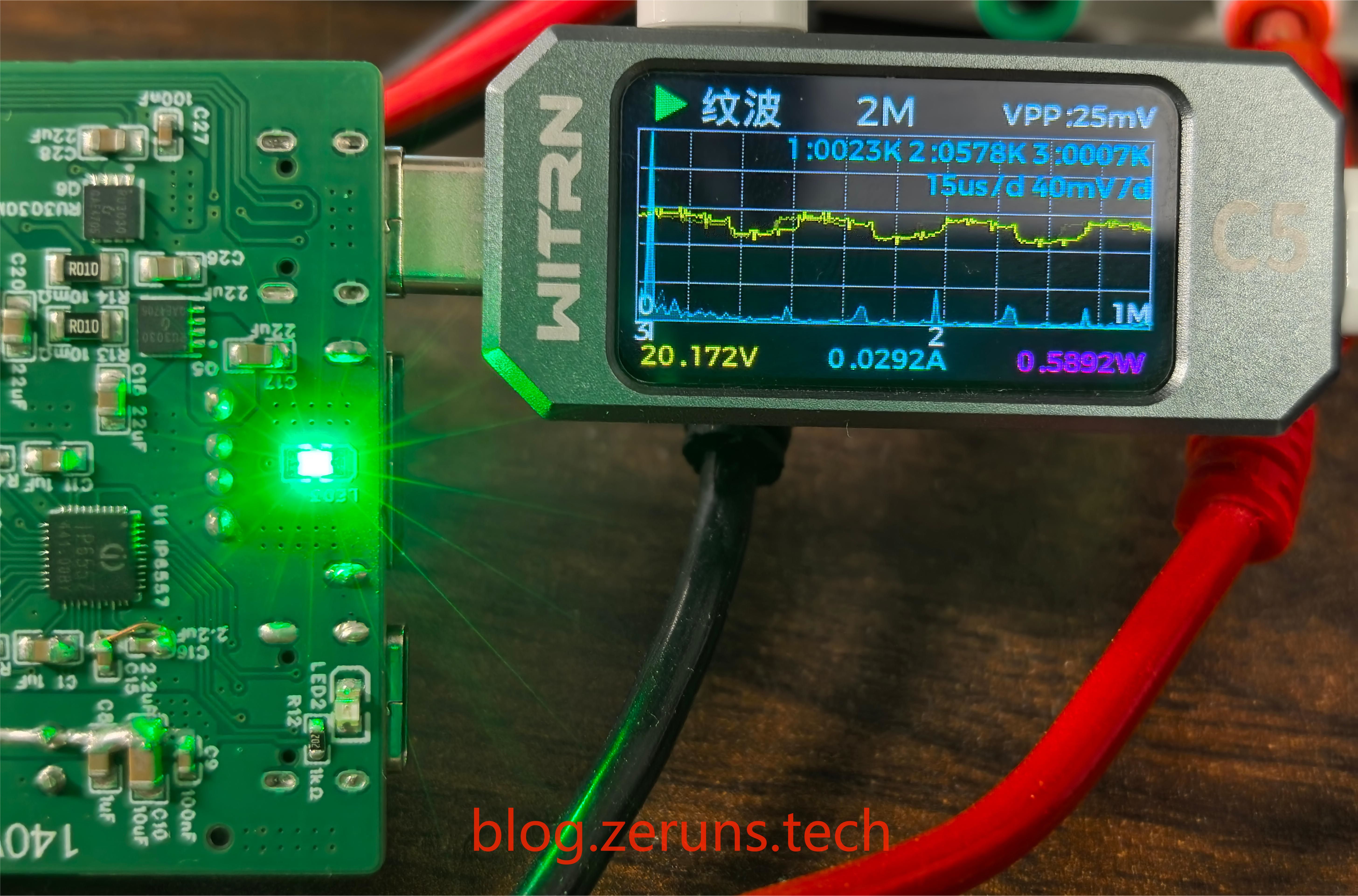
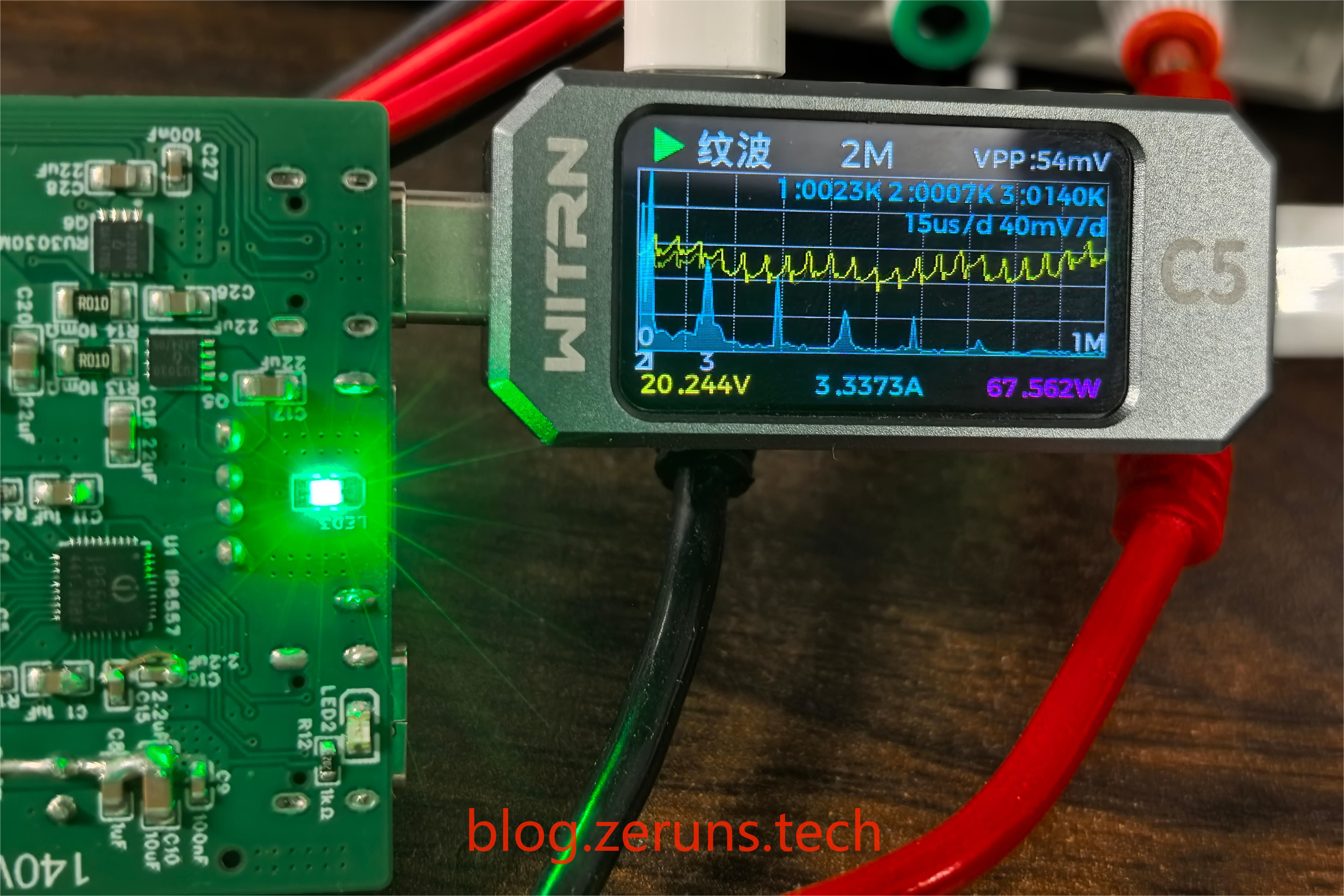
W) Output Voltage (V) Output Current (A) Output Power (W) Conversion Efficiency (%) 23.997 6.459 154.997 27.592 5.323 146.872 94.758 11.999 9.598 115.166 19.980 5.345 106.793 92.729 8.299 8.897 73.836 20.030 3.336 66.820 90.498 23.997 4.686 112.450 20.100 5.341 107.354 95.468 23.997 1.764 42.331 12.001 3.337 40.047 94.606 IP6538 Maximum Conversion Efficiency 96.719% Input Voltage (V) Input Current (A) Input Power (W) Output Voltage (V) Output Current (A) Output Power (W) Conversion Efficiency (%) 24.008 0.795 19.086 5.165 3.315 17.122 89.708 24.008 1.265 30.370 12.217 2.335 28.527 93.930 24.008 2.910 69.863 20.243 3.338 67.571 96.719 24.008 Thermal imaging of heat generation: 0.933 22.399 9.084 2.245 20.394 91.045 PCB front and back thermal images after 5 minutes of full load output at port C1 (140W). The MOSFET temperature reached over 111℃. A heatsink or aluminum alloy casing is required for full load output, with heat conducted to the casing via a thermal pad. Thermal imaging of PCB front and back images after 10 minutes of full load output at port C2 (65W). The IP6538 chip reached a maximum temperature of around 75℃, allowing for prolonged full load operation without a heatsink. Thermal imaging of the aluminum alloy casing after 10 minutes of simultaneous full load output from both ports. The casing reached a maximum temperature of around 65℃. Due to the separate upper and lower casings with a gap, heat is concentrated in the lower casing, making it difficult for heat to transfer to the upper casing. Ripple rate calculation formula: $$ Ripple rate = frac{(peak ripple - valley ripple)/2}{average output voltage} imes 100% $$ The peak-to-peak ripple value of port C1 outputting 28V (actual 27.6V) is around 33mV, with a ripple rate of 0.059%. The peak-to-peak ripple value of port C1 outputting 28V 5.2A is around 178mV, with a ripple rate of 0.323%. The peak-to-peak ripple value of port C2 outputting 20V under no-load is around 25mV, with a ripple rate of 0.062%. The peak-to-peak ripple value of port C2 outputting 20V 3.3A is around 54mV, with a ripple rate of 0.133% . The ripple performance is quite good. Schematic IP6557: IP6538: Top layer of PCB :

Bottom Layer:

Component Purchase Links
Most of the components used in this project can be purchased here:
0603 Resistor/Capacitor Sample: https://s.click.taobao.com/XXCyZht
Type-C 16P Female Socket: https://s.click.taobao.com/6HYxZht
IP6557 Chip: https://s.click.taobao.com/Jor7Fit
IP6538 Chip: https://s.click.taobao.com/aPw6Fit
AGM405Q MOSFET: https://s.click.taobao.com/0aR6Fit
XT30PW-M Interface: https://s.click.taobao.com/cPB6Fit
Flat Wire Inductor PQ2012 10μH: https://s.click.taobao.com/SoguZht
50125 Horizontal 10μH 10A Toroidal Inductor: https://s.click.taobao.com/B6quZht
35V 220μF solid capacitor: https://s.click.taobao.com/CxL3Fit
35V 100μF solid capacitor: https://s.click.taobao.com/z9FtZht
Aluminum alloy casing: https://s.click.taobao.com/xmRkZht
It is recommended to purchase components from LCSC Online Store: https://activity.szlcsc.com/invite/D03E5B9CEAAE70A4.html
Click on the BOM in the LCSC open-source link to immediately place an order on the LCSC Online Store; you can import the required components into your shopping cart with one click. Download
links
below include: LCSC EDA project, schematic PDF file, datasheets for various chips used, and 3D model file of the casing.
Baidu Cloud download link: https://pan.baidu.com/s/1RJNC_v2P1YijWpv1sFXowQ?pwd=89hi Extraction code: 89hi
123 Cloud download link: https://www.123pan.com/s/2Y9Djv-BItvH.html Extraction code: 0nEm
If you find this useful, you can tip me through the 123 Cloud links above. If it's a WeChat article (WeChat Official Account: zeruns-gzh), you can also click "Like Author" at the bottom of the article to tip me. Thank you.
Other recommended open-source projects
include: a three-phase power consumption data logger for easy monitoring of home electricity usage (https://blog.zeruns.tech/archives/771.html);
an STM32F407-based LVGL project template (MSP3526 screen), including FreeRTOS and bare-metal versions (https://blog.zeruns.tech/archives/788.html);
an STM32-based synchronous rectification Buck-Boost digital power supply (https://blog.zeruns.tech/archives/791.html); and
the LM25118 automatic buck-boost adjustable DC-DC power module (https://blog.zeruns.tech/archives/727.html).
EG1164 high-power synchronous rectification boost module open source, with a maximum efficiency of 97%: https://blog.zeruns.tech/archives/730.html
4G environmental monitoring node based on Zeruns Air700E (data on temperature, humidity, air pressure, etc.), uploading to Alibaba Cloud IoT platform via MQTT: https://blog.zeruns.tech/archives/747.html
Smart electronic load based on CH32V307 open source, an embedded competition entry open source: https://blog.zeruns.tech/archives/785.html
EG1151 high-power synchronous rectification adjustable boost/buck power supply module (supports Type-C PD fast charging input) open source: https://blog.zeruns.tech/archives/794.html


 京公网安备 11010802033920号

 SFT37S60-10K491E-F


