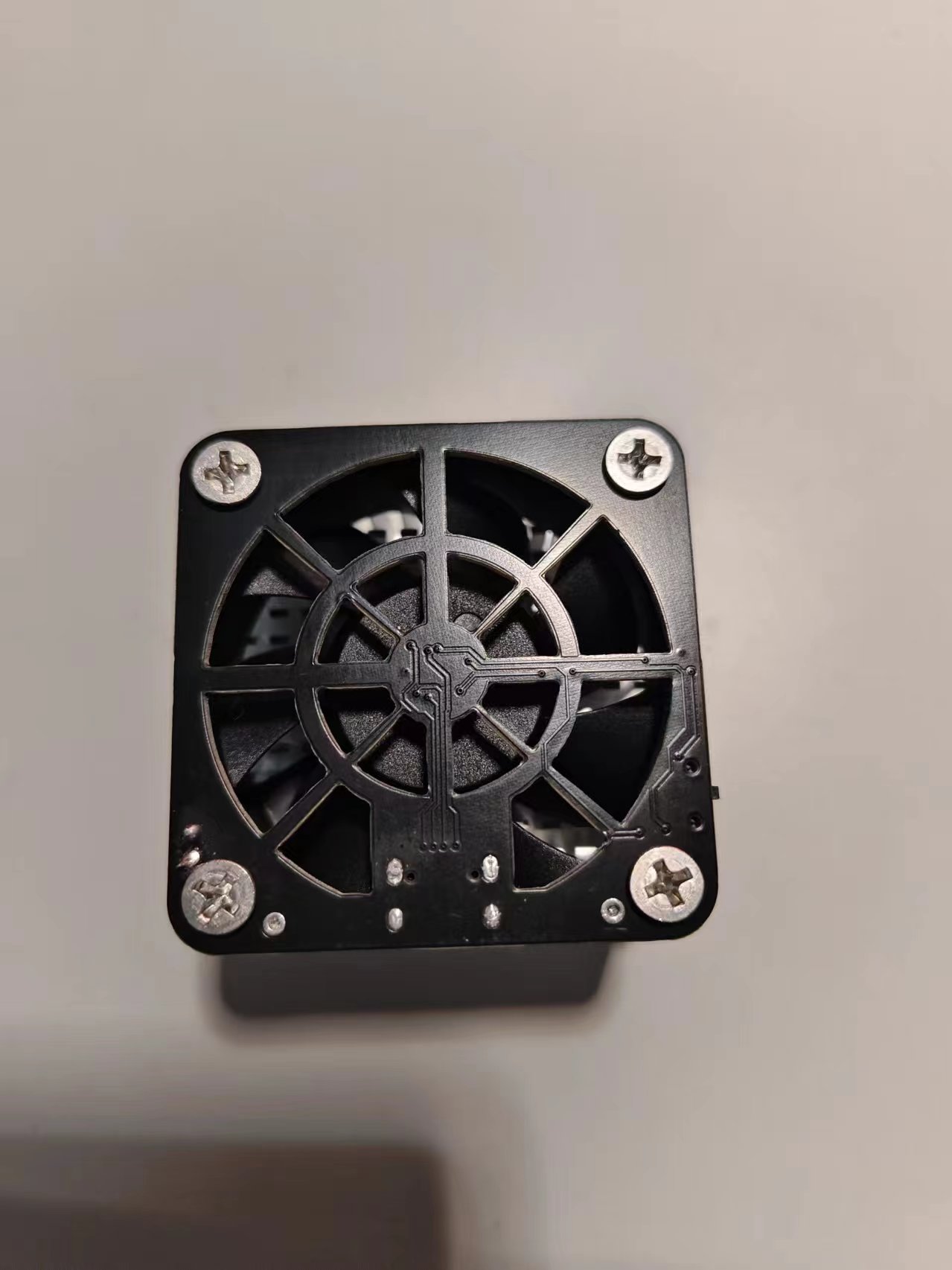
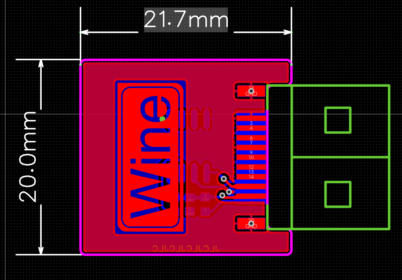
This is the dimensions diagram. Here's
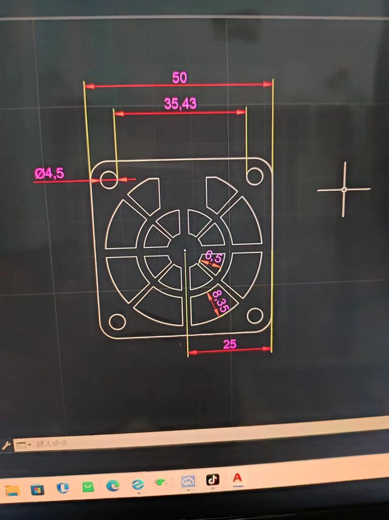

what it will look like after installation.
200f18db92a3f04d6f7179ec44b83e63.mp4
PDF_Fan shroud based on ch224kPD decoy 50x50 5-9-12 switchable.zip
Altium_C224kPD decoy-based fan shroud 50x50 5_9_12 switchable.zip
PADS_Fan Cover 50x50 5_9_12 Switchable Based on ch224kPD Decoy.zip
BOM_Fan shroud based on ch224kPD decoy 50x50 5_9_12 switchable.xlsx
91630
Smart door lock
This servo door lock, based on the LCSC STM32F103C8T6 microcontroller, is equipped with modules for voice control, Bluetooth, DHT11, and OLED display. It allows for door opening via voice and Bluetooth control of the servo motor, and displays the control mode (voice, Bluetooth), servo angle, and current ambient temperature and humidity on the OLED screen.
Project Overview:
This project is an intelligent servo motor door lock system integrating multiple sensors and communication modules. The core control unit uses the LCSC STM32F103C8T6 microcontroller. The system achieves contactless door lock control through voice recognition and Bluetooth technology, and is equipped with a DHT11 temperature and humidity sensor and an OLED display to provide real-time environmental information and operational feedback.
Project Functions:
This project designs a multi-functional intelligent servo motor door lock system with the following core functions:
Voice Control: Through the integrated voice recognition module, users can issue voice commands to control the opening and closing of the servo motor, achieving automatic door unlocking.
Bluetooth Remote Control: Users can connect to the door lock system via Bluetooth and remotely control the door lock using a mobile phone or other Bluetooth devices.
OLED Display: The system is equipped with an OLED display to show the current operating mode (voice or Bluetooth), the opening and closing angle of the servo motor, and environmental temperature and humidity data acquired by the DHT11 sensor in real time.
Temperature and Humidity Monitoring: The DHT11 sensor can monitor the environmental temperature and humidity in real time and display the data to the user through the OLED display, ensuring the user has an intuitive understanding of environmental conditions.
Status Feedback: When performing door opening or closing operations, the system displays the current servo angle on the OLED screen, providing operational feedback to the user.
Project Parameters:
This design uses the LCSC STM32F103C8T6 microcontroller, featuring a high-performance ARM Cortex-M3 core, providing powerful processing capabilities.
The design employs the LD3320 integrated high-performance voice recognition module, accurately recognizing user voice commands for contactless door lock control.
A Bluetooth HC-05 module supports low-power Bluetooth communication, ensuring stable connection with smart devices.
An SG90 servo module provides precise angle control, ensuring smooth door lock opening and closing.
A fully digital DHT11 temperature and humidity sensor with a wide temperature measurement range meets general needs;
a 0.96-inch OLED display provides clear text display for showing operating modes, servo angles, and ambient temperature and humidity.
The system supports 5V DC power input and can be powered via USB interface.
Principle Analysis (Hardware Description)
The design principle of this project can be divided into the following core parts: voice recognition, Bluetooth communication, servo motor control, temperature and humidity monitoring, and OLED display output. This project mainly enables door opening via voice and Bluetooth control of the servo motor. When the user outputs corresponding commands via voice or Bluetooth, the corresponding control operation is performed. Simultaneously, the control mode (voice, Bluetooth), servo motor angle, and current ambient temperature and humidity are displayed on the OLED screen.

Figure 1 – Voice Recognition:
The LD3320 integrates a high-performance voice recognition module, which can accurately recognize the user's voice commands, realizing contactless door lock control. It operates on 5V power and communicates via interrupts (9600 baud rate) through PA2 and PA3.

Figure 2 – Bluetooth HC-05 Module:
The Bluetooth HC-05 module is responsible for wireless communication with the user's smart device (such as a smartphone). The user sends a door opening command via Bluetooth through a smart device (such as a smartphone). After receiving the command, the Bluetooth module controls the servo motor to execute the door opening action. It operates on 5V power and communicates via interrupts (115200 baud rate) through PA9 and PA10.
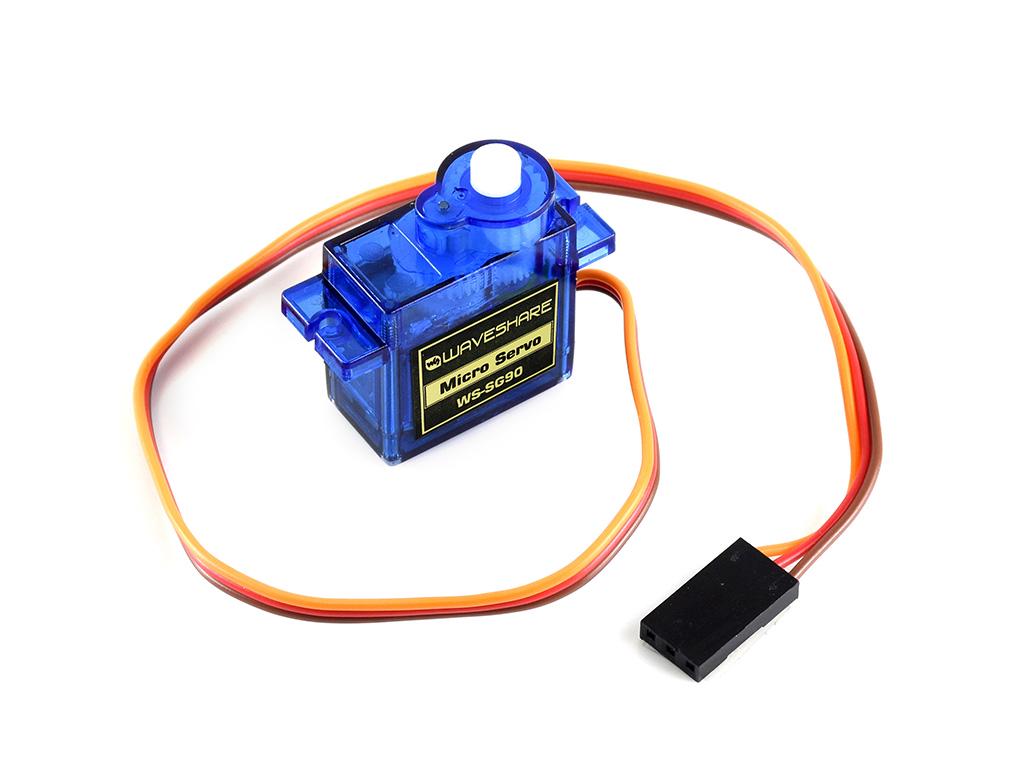
Figure 3 – SG90 Servo Module:
The SG90 servo module receives PWM signals from the microcontroller and adjusts the servo's rotation angle according to the PWM duty cycle to open and close the door lock. The PWM signal is output through CH1 (PA0) of TIM2 to control the servo's rotation angle.
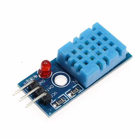
Figure 4 – DHT11 Module:
The DHT11 sensor monitors the ambient temperature and humidity and transmits the data to the STM32 via PB11. After processing the data, the STM32 sends it to the OLED display via the IIC interface.
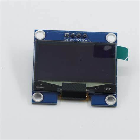
Figure 5 – OLED Module:
The OLED display shows the system's real-time operating status, including operating mode, servo angle, and ambient temperature and humidity.
The display communicates with the STM32 via the IIC interfaces (PB8, PB9) to receive and display data sent by the microcontroller.
The software code is as follows
: `int main(void)
{
OLED_Init();
Servo_Init();
USART1_Init(115200);
USART2_Init(9600);
DHT11_Init();
OLED_ShowString(2, 1, "Angle:");
OLED_ShowString(1, 1, "Mode:");
while (1)
{
//servo motor to open/close door
control_door();
//OLED display mode
oled_mode();
//OLED display temperature and humidity
oled_dht();
} }
`
This displays the main program code. See the project attachment for detailed code.
**Notes :**
The voice module requires downloading the corresponding program via serial port (see attachment).
The Bluetooth module requires AT command settings; many are available online.
**Note:** Modules must be connected correctly; do not connect them backwards. **Note
:** Modules may vary; adjust the spacing between modules on the PCB accordingly. For example, increase the spacing between the LD3320 and STM32, and modify the position of the DHT11. **
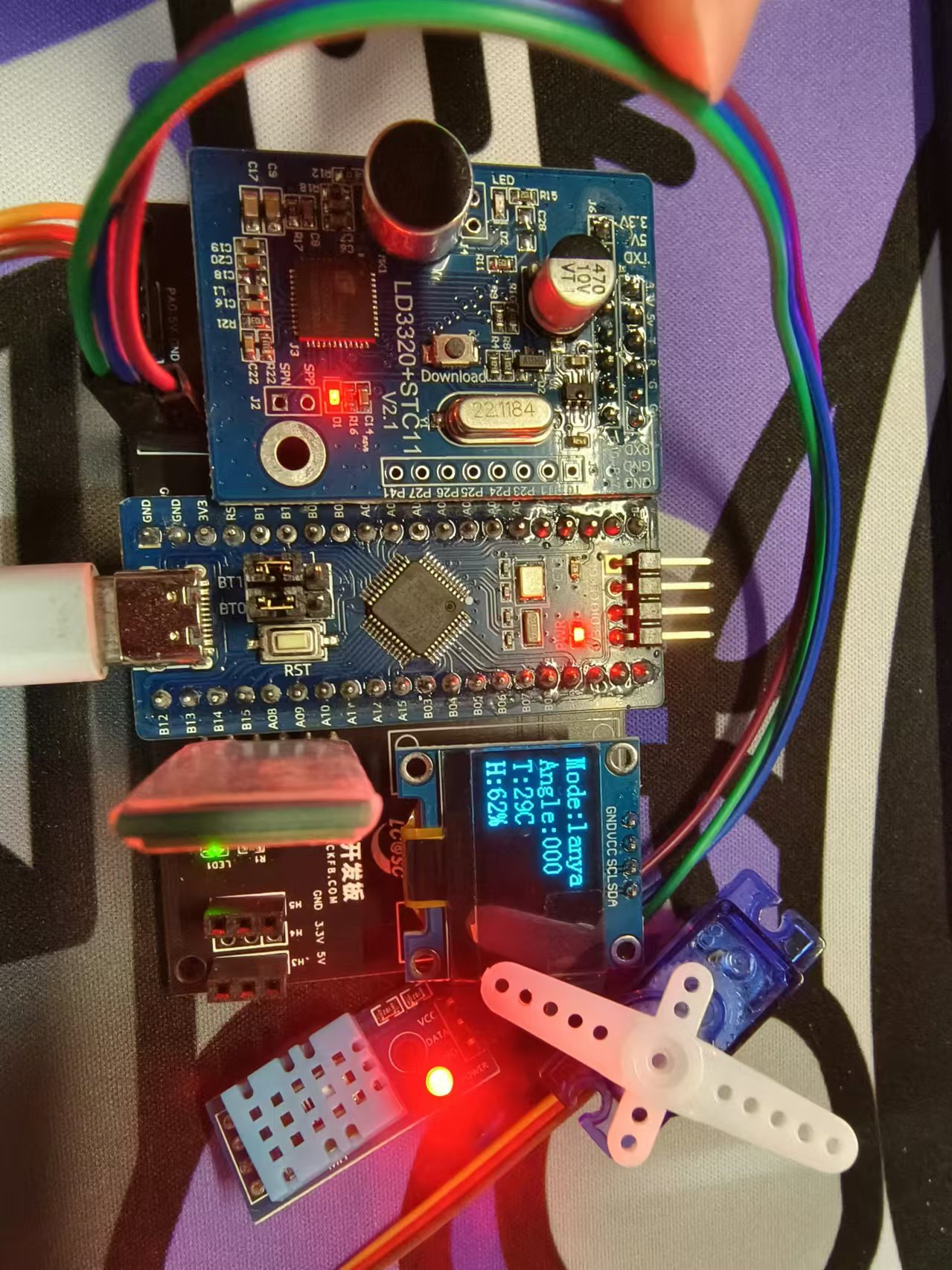
Assembly Process:
** Connect the corresponding modules; do not connect them backwards. Figure 6: Actual product
image
Smart door lock.zip
LDV7 Voice Recognition Module (Password Mode).zip
Documentation.txt
Smart door lock demonstration video.mp4
Smart door lock demonstration video 720p.mp4
PDF_Smart Lock.zip
Altium Smart Lock.zip
PADS_Smart Lock.zip
BOM_Smart Lock.xlsx
91631
Voron CAN XT30 2+2 to MX3.0 2x2P
CAN expansion board for connecting CAN lines from Voron XT30 2+2 interface to MX3.0 2x2P interface.
Voron CAN XT30 2+2 to MX3.0 2x2P Interface Converter.
For CAN expansion boards compatible with Voron XT30 2+2 interface CAN lines to MX3.0 2x2P interface.
Soldering aid mold design and 3D printing files are included to facilitate interface soldering.
Housing design and 3D printing files are also included. Note that when printing the housing, a layer pause is required for PCB placement and infill.
SolderingTemplate.f3d
SolderingTemplate.stl
Shell.f3d
Shell Body.stl
Shell Padding.stl
PDF_Voron CAN XT30 2+2 to MX3.0 2x2P.zip
Altium_Voron CAN XT30 2+2 to MX3.0 2x2P.zip
PADS_Voron CAN XT30 2+2 to MX3.0 2x2P.zip
BOM_Voron CAN XT30 2+2 to MX3.0 2x2P.xlsx
91634
mori's GBASP original replica PCB
The GBASP motherboard was built based on open-source schematics from GitHub and scanned images of the original GBASP motherboard.
Thanks to the original author Gekkio for the open-source schematic: gb-schematics.
Update Log
2024-10-15: VDRV3 was missing a circuit, now complete. The circuit is located between pin 4 of U4 and VDRV3. For those who have already boarded and moved the board for troubleshooting, please run a jumper wire from pin 4 to the VDRV3 test point; it's very close.
2024-10-16: v1.1 verified and working normally.
The initial motivation for drawing this version was that I bought a refurbished GBASP with jumper wires, which annoyed me. So, on a whim, I searched GitHub extensively, but couldn't find any ready-made PCBs or gerbers, only schematics.
After importing it into LCSC EDA, I found that even the packages were missing. Faced with hundreds of fatal errors, I had to painstakingly complete the packages one by one. It took several months to reach this level.
The replication accuracy is only about 80%. Many silkscreens and fonts are not completely identical; they are slightly thinner than the original, and the large areas of white highlights around the buttons are not addressed.
I don't think this is a project for sale, so there's no need for a complete replica. Otherwise, it would be easier to just buy a 1:1 replica from Xianyu (a second-hand marketplace).
The main purpose of this project is to help those who want to repair things but don't have a component diagram, providing a repair reference.
Those who feel confident in their DIY skills can also try to reassemble the board themselves.
Regarding the BOM, the resistors and capacitors are corresponding. The transistors and diodes can theoretically be used directly. Other chips require reassembly.
Regarding the original console:
Let me promote our retro game console DIY exchange group: 771688226 (QQ group).
Our group currently has open-source projects including the GBA flashcart Chisflah ferroelectric version and the Chisflash SRAM version.
More replica projects will be open-sourced in the future, so stay tuned!
Regarding open-source emulators:
GBA-style open-source handheld console: FunKey A32G.
FunKey handheld console building and discussion group: Experts in the group help answer building questions, and there are various FunKey handheld console building materials.
FunKey enthusiasts group 1: 825088536 (full).
FunKey enthusiasts group 2: 921179758 (password required, any password will do).
PDF_mori's GBASP Original Replica PCB.zip
Altium_mori's GBASP original replica PCB.zip
PADS_mori's GBASP original replica PCB.zip
BOM_mori's GBASP original replica PCB.xlsx
91635
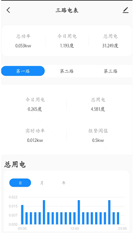
Pui Ching Graffiti Electricity Meter - Three-way
A three-way WiFi meter made using a 17h65 BLE chip, Tuya WBR3, and Peizheng power module.
This project
introduces a three-way WiFi power meter built using a 17H65 BLE chip, Tuya WBR3, and Peizheng power module.
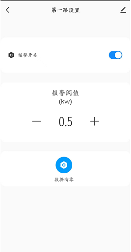
Through configuration, it can monitor home electricity usage in real time
and set alarm power levels.
It also monitors three power sources simultaneously. **
Note:** This project involves high-voltage electricity; please exercise caution. The project owner is not responsible for any consequences arising from its use. Open
source link
- Software open source link
. All materials,
code, and project configurations are attached.
Configure the Tuya platform product key in the protocol.h file to use
the Tuya platform. Configure
data points. Configure
Tuya data points.
Configure the Studio panel. Configure
the hardware
casing. **
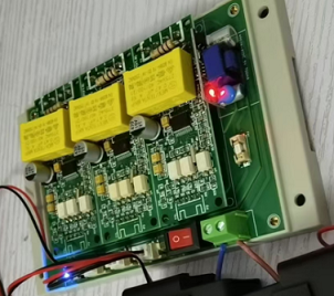
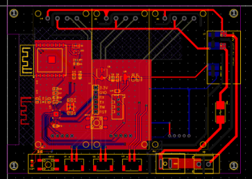
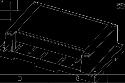
PS:** Why is it a four-layer board? Because the PCB exceeds 10cm. [dog emoji]
h65_ty_pet_power-main.zip
PDF_Peizheng Graffiti Electricity Meter - Three-way.zip
Altium_培正画画电米-三路.zip
PADS_Peizheng Graffiti Electricity Meter - Three-Way.zip
BOM_Peizheng Graffiti Electricity Meter - Three-way.xlsx
91636
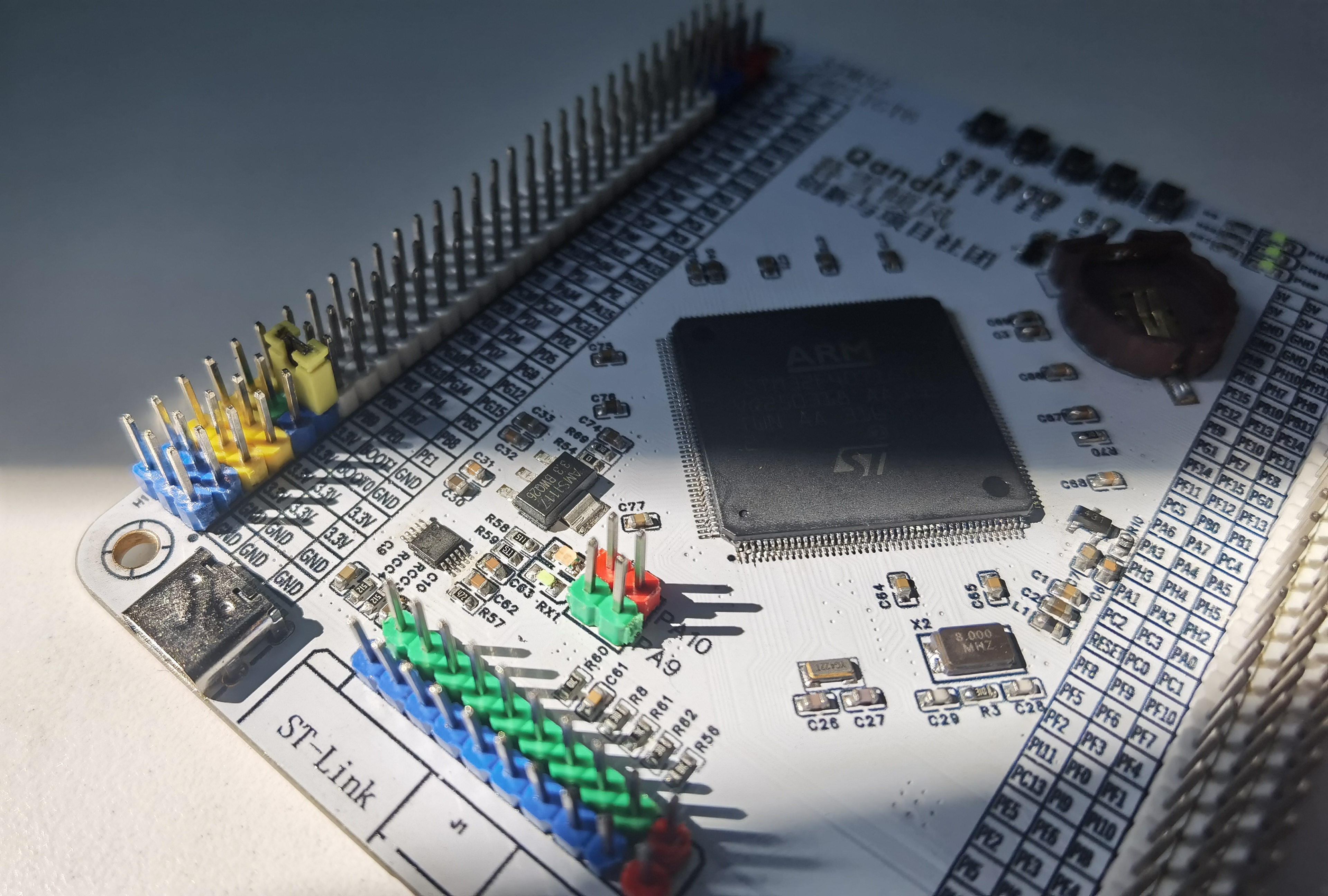
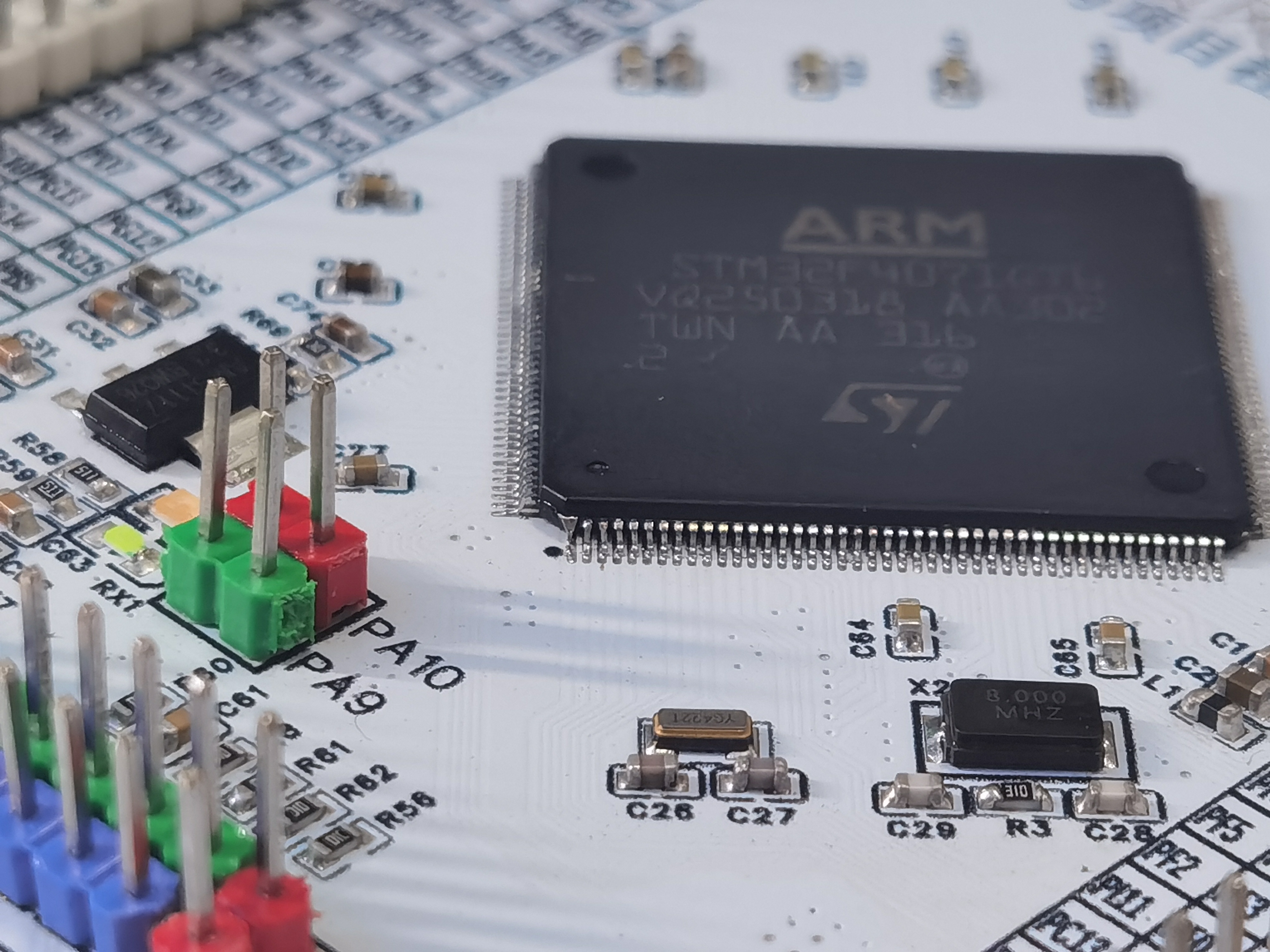
STM32 minimum system board
I found a cheap 32-chip, so I designed a board. The F401 is basically cheaper than the F103 (and its performance is better than the F103 in most common functions except for CAN).
(I have also designed F103F4P6, F103C8T6, and F407VET6, which I will share later.)
I. Team Introduction
: We are electrical engineering students who design circuit boards in our spare time.
II. Design Summary:
I saw a cheap chip online, the F401RCT6, which is even cheaper than some vendors' F103 chips. I wanted to make a minimal system board for our project. There's not much to say about the details. It has an onboard download port and a dedicated serial port 1 for connecting to a Type-C port for serial communication and downloading. The converter is simply an AMS1117 with two tantalum capacitors; nothing special. All pins except the crystal oscillator and download port are brought out, and it supports 5V power supply and 3V3 pin output. The main advantage of the FRKVO
(https://detail.tmall.com/item.htm?_u=g202ac0tifcb0a&id=672543808265&skuId=4847621849917&spm=a1z09.2.0.0.116b2e8djFRKVO
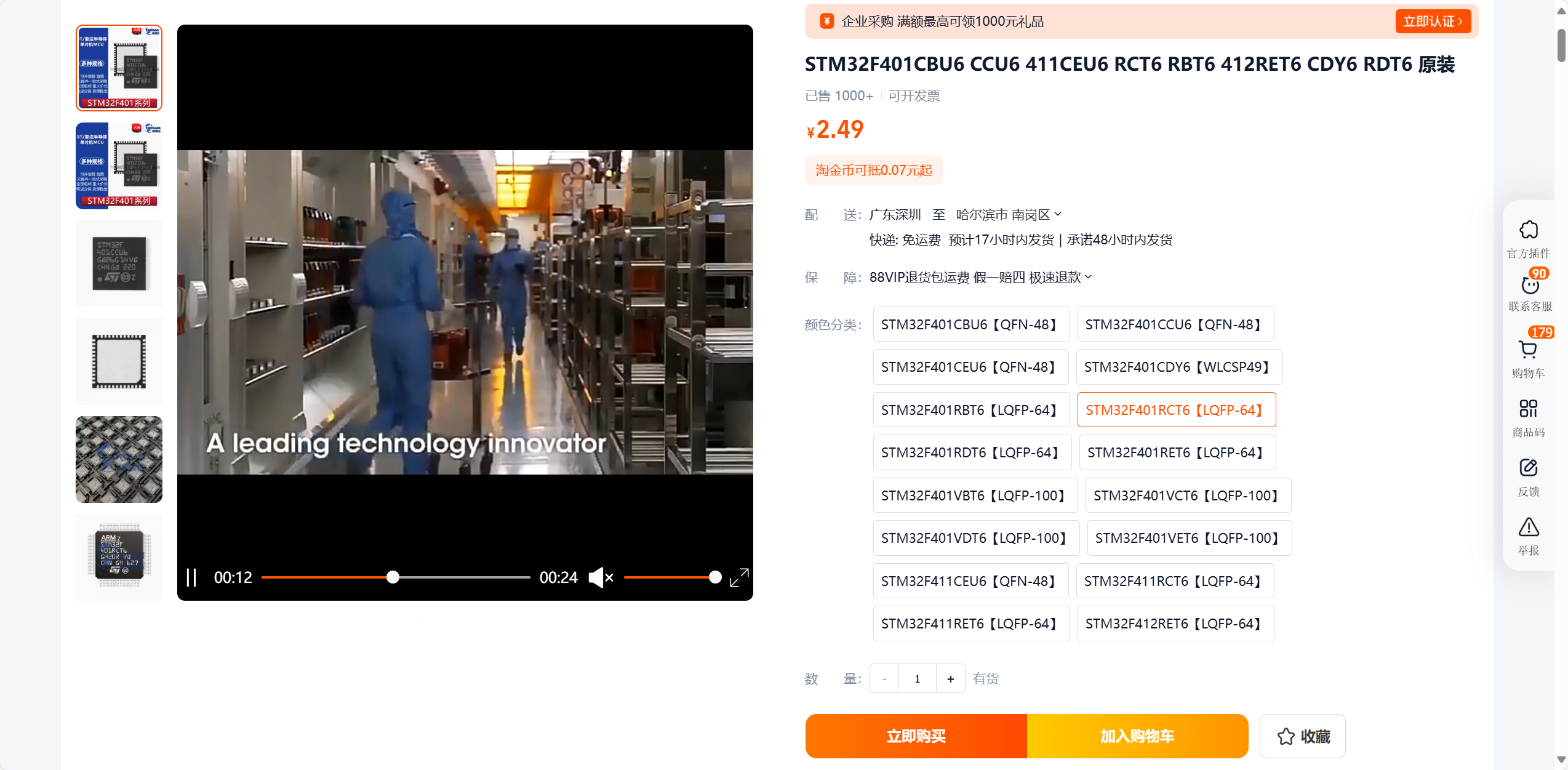
) is its low price. Excluding resistors
, capacitors, and LEDs, the cost is only about five yuan, similar to the price of a standard STM32F103C8T6 minimum system board. In terms of performance, it far surpasses the F103. It features a Cortex-M4 core, an 84MHz clock speed, 256Kbytes of Flash memory, an FPU, and a higher clock speed, enabling real-time calculations that the F103 cannot perform. With 3 SPIs, 2 IICs, 3 UARTs, and 8 timers, it's more than sufficient for normal project work. The only drawback is the lack of CAN and USB ports. I used this chip to create a FOC driver, and it works fairly well.
III. Hardware Circuit Composition
1. Power Input:
Type-C is 5V, and the download port is 3.3V. The pins can accept either 3.3V or 5V; refer to the pin labels for details.
2. Converter:
AMS1117 converter, very stable, with sufficient current, can drive small motors, OLEDs, TFTs, and other common modules (however, only recommended for driving small screens and other low-power components). The two tantalum capacitors can be replaced with 10uF capacitors, or small surface-mount ceramic capacitors can be used instead; it doesn't matter.
3. Serial Port:
Use CH340N to connect to USART1 for serial communication. It works as soon as it's connected to a computer. My FlyMCU can download (sometimes the chip locks and downloads fail, I don't know why).
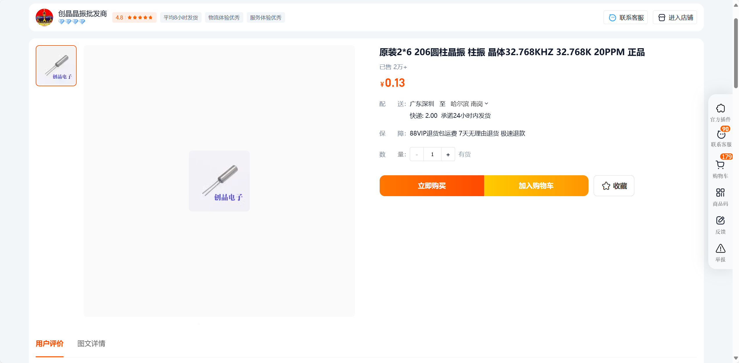
4. Crystal Oscillator:
I bought one from this company; it works well. If you don't use an RTC, you don't need to solder the 32.768 crystal oscillator and its capacitors.

5. Reset and Startup:
Normal reset circuit; just copy it, nothing much to say. The default boot mode (boot0 = 0) is Flash memory boot mode. Pressing BOOT0 changes it to (boot0 = 1; boot1 = 0) System memory boot mode. In this mode, serial port code can be downloaded; learn more online.
6. Display:
Two LEDs are used to display 5V and 3.3V. No additional onboard LEDs are reserved; I don't think it's necessary. You can write your own code to check the pin levels.
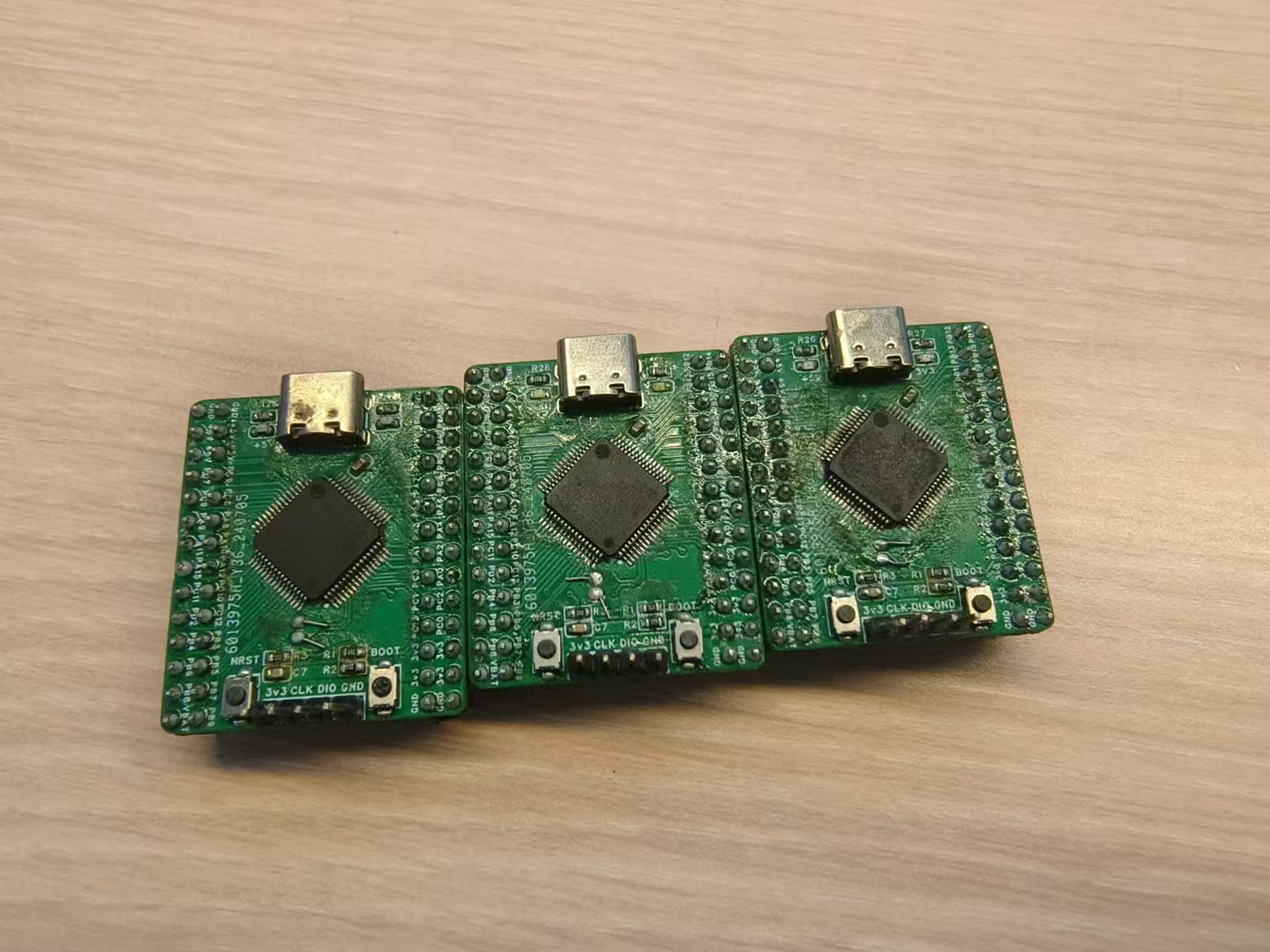
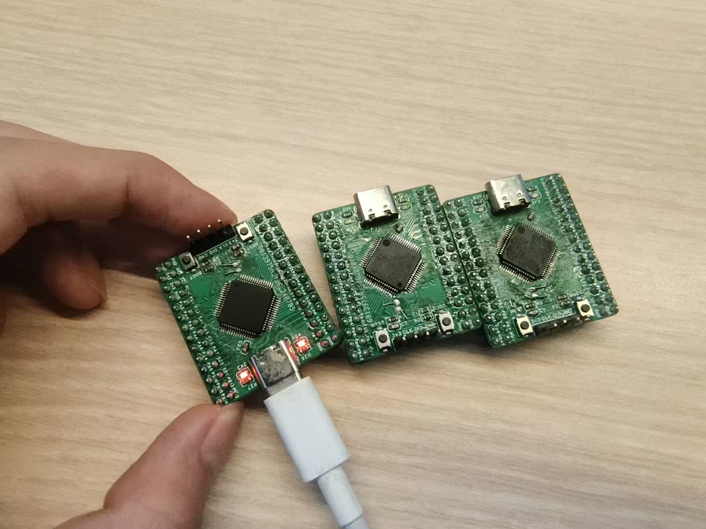
IV. Physical Demonstration:
Basic I/O pins have been tested and are usable. Timer and communication pins are also generally usable.
V. Precautions:
None at present.
PDF_stm32 Minimum System Board.zip
Altium_stm32 Minimal System Board.zip
PADS_stm32 Minimum System Board.zip
BOM_stm32 Minimum System Board.xlsx
91638
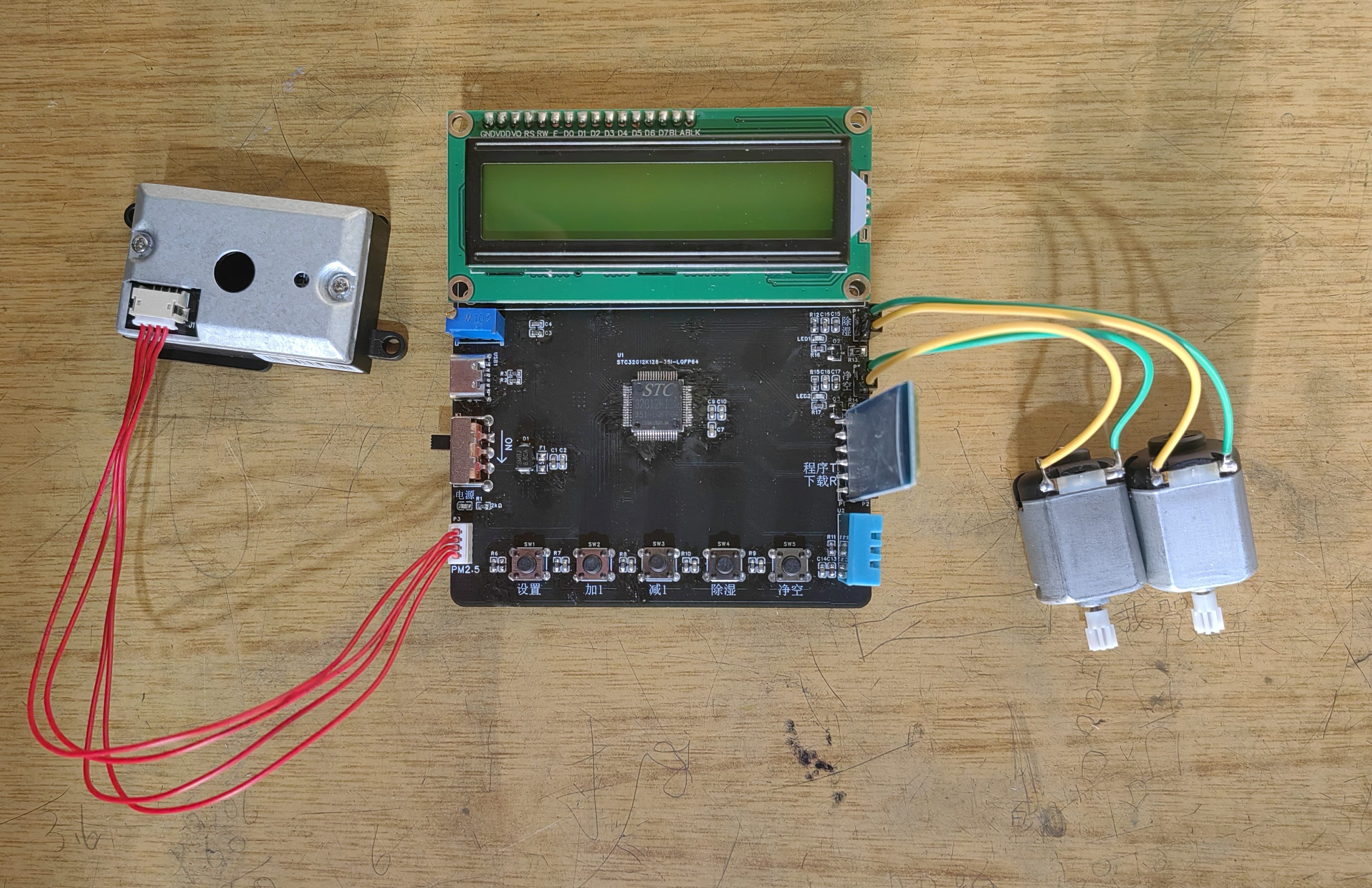
Home Air Quality Monitoring System Based on STC32 Microcontroller
The system uses a DHT11 sensor to detect ambient temperature and humidity, and a PM2.5 sensor to monitor PM2.5 levels in the air. The collected data is displayed in real-time on an LCD1602 screen and transmitted to a mobile phone via Bluetooth. Based on the air quality, the system will take actions such as activating an air purifier.
This home air quality monitoring system, based on the STC32 microcontroller, uses a DHT11 sensor to detect
ambient temperature and humidity data, and a PM2.5 sensor to monitor PM2.5 levels. The collected data is displayed in real-time on an LCD1602 screen and transmitted to a mobile phone via Bluetooth. The system will then perform actions based on the air quality, such as turning on an air purifier. The system can also be started and stopped via a mobile phone or by pressing buttons. II. Design Connection Port Description 1. Data from the DH11 temperature and humidity sensor is transmitted via port P4.7. 2. PM2.5 detection uses an external module with UART as the communication protocol, so serial port 4 (RXD4, TXD4) is used. 3. Data from the LCD1602 is transmitted via P0, using three control lines: EN connects to port P4.4, RW connects to port P4.3, and RS connects to port P4.2; backlight control connects to port 4.1. 4. Buttons are connected to ports P0.0, P0.1, P0.3, P0.4, and P4.6. 5. Bluetooth communication uses serial port 3 (RXD3, TXD3). 6. Indicator lights are driven by ports P7.0 and P7.1. 7. Motor drives are driven by ports P7.2 and P7.3. III. Software Description I. Software Requirements Functional Analysis 1. Basic Part (1) Data acquisition of DHT11 (GPIO initialization) (2) Data acquisition of PM2.5 sensor (UART4 serial port configuration) (3) Display of LCD1602 (GPIO initialization) (4) Button detection (GPIO initialization) (5) Data transmission and reception of Bluetooth module (UART3 serial port configuration) (6) LED light drive and motor drive (GPIO initialization) 2. Specific Functional Analysis In addition to the basic part of the functions, the following functions also need to be implemented: (1) The safety thresholds of temperature, humidity and PM2.5 can be set by buttons. (2) When the temperature, humidity or PM2.5 exceeds the threshold, corresponding operations are performed (starting the LED light and motor). (3) The motor can be manually started and stopped without being affected by thresholds (i.e., the user's control authority is higher than the system's control authority). (4) Temperature, humidity and PM2.5 values can be transmitted to the mobile phone via Bluetooth for display, and the mobile phone can also control the motor to start or stop. IV. Physical Demonstration ## Precautions The designed system does not have a reset button. To reset, please turn the power switch back on.
Home air quality monitoring system based on STC32 microcontroller ~1.mp4
board_demo.hex
project_stc32g12k128 (program).zip
PDF_Home Air Quality Monitoring System Based on STC32 Microcontroller.zip
Altium-based Home Air Quality Monitoring System (based on STC32 microcontroller).zip
PADS_Home Air Quality Monitoring System Based on STC32 Microcontroller.zip
BOM_Home Air Quality Monitoring System Based on STC32 Microcontroller.xlsx
91639
HDMI decoy
HDMI (High Definition Multimedia Interface) decoys with a cost that is rounded to zero
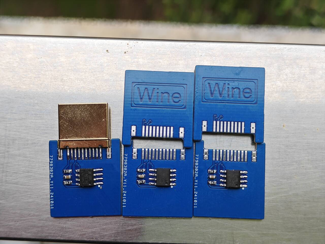
This HDMI decoy is
a DIY project I created. It uses EEPROM to simulate the Extended Display Identification Data (EDID) of a monitor via the I2C bus, tricking HDMI signal source devices into believing they are connected to a specific monitor. The HDMI signal source device reads the monitor's EDID data to obtain information such as supported resolution and refresh rate. This decoy, using custom EDID data, can trick the signal source device into outputting user-specified display parameters.
How it works:
The HDMI signal source device communicates with the monitor via the I2C protocol. The monitor's EDID information is stored in the EEPROM. This project uses a 24C32 EEPROM as memory, which can easily store custom-generated EDID data. The device reads the EDID data in the EEPROM via I2C, believing it to be genuine information from the monitor. Other EEPROMs of suitable capacity can replace the 24C32, as long as the generated EDID can be stored correctly.
Implementation process:
Custom EDID: Use an EDID generation tool to create or edit supported monitor parameters such as resolution and refresh rate.
I2C Communication and EPROM Storage: Accesses a 24C32 (32K) or other suitable capacity EEPROM via I2C to write the generated EDID. The HDMI signal source device reads this data and adjusts its output accordingly.
EDID Writing and Modification: The EDID data in the EEPROM can be updated at any time, flexibly customizing the display parameters supported by the device.
Application Scenarios:
Remote Desktop and Virtual Display: In the absence of a physical monitor, the decoy device allows the computer to continue working normally, enabling remote desktop connections and other needs.
Debugging and Testing: The device can be used for debugging video equipment, easily testing its behavior under different display parameters.
Forced Resolution Output: The decoy device can control the signal source to output a specific resolution and refresh rate to meet specific application requirements.
The other
PCB components weren't compressed much because I thought they'd be too small for easy plugging and unplugging. Further compression is possible
if needed. If you need to trick a DisplayPort, just change it to a DisplayPort interface. Nothing else needs much modification. The only thing to note is that HDMI power is 5V, and DisplayPort is 3V3. Make sure the EEPROM supports it
. You can use a CH341 to flash the EDID data before soldering. Before connecting it to the computer, check for short circuits in the power supply. For
a more advanced setup, you can use the microcontroller's I2C to simulate an EDID in real time, dynamically changing the resolution and refresh rate.
PDF_HDMI Deception.zip
Altium_HDMI Deception.zip
PADS_HDMI Deceptive.zip
BOM_HDMI Deceptive.xlsx
91640
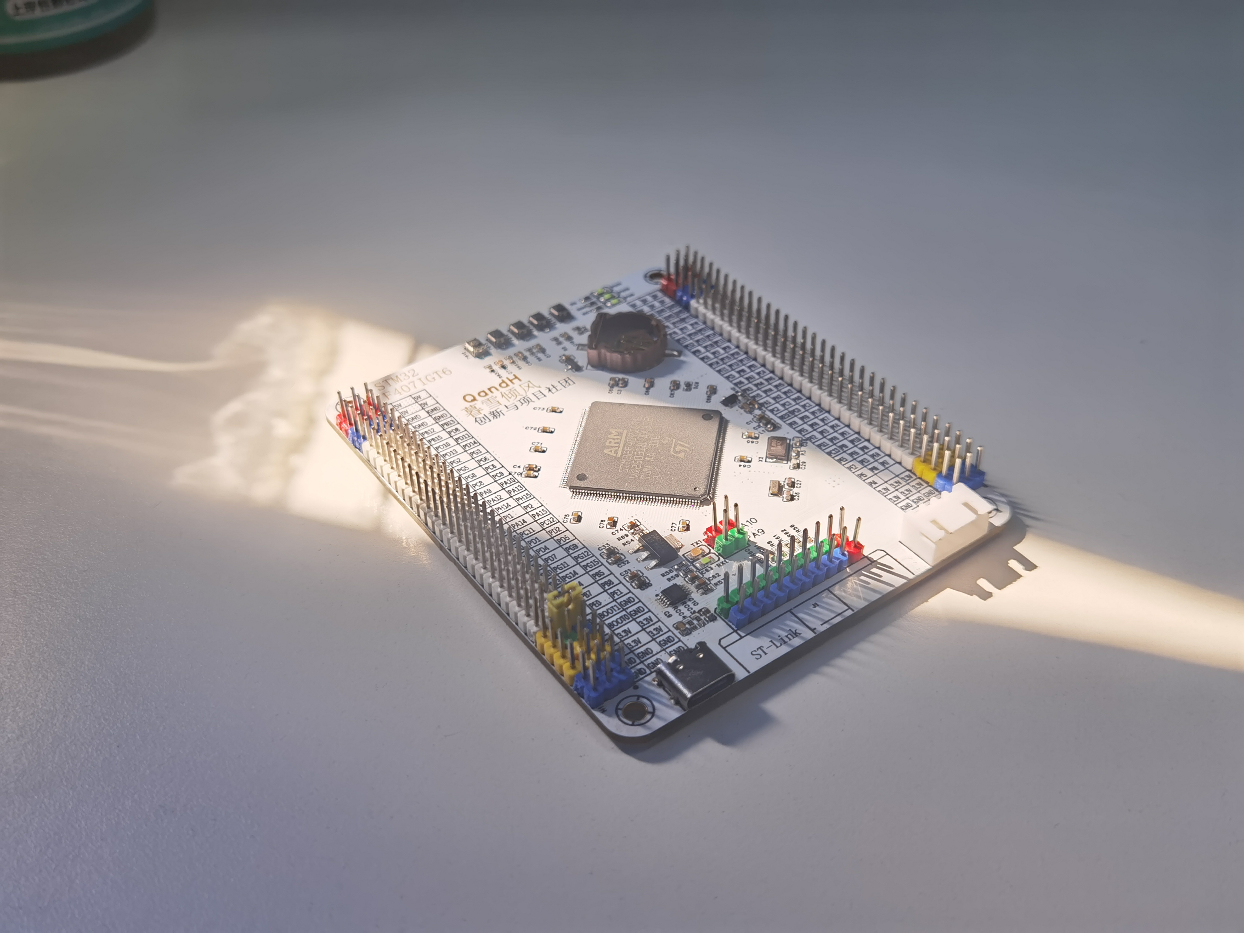
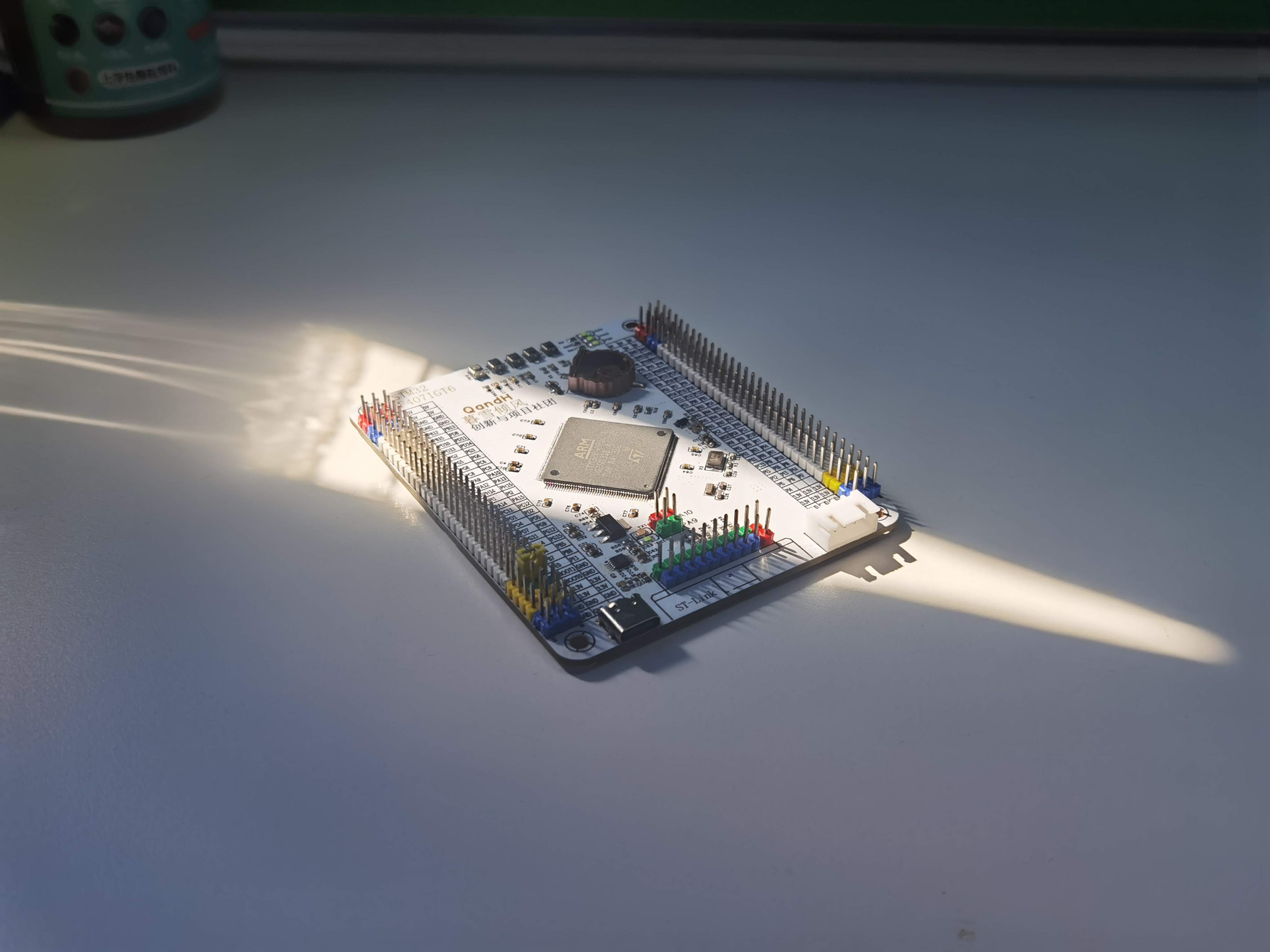
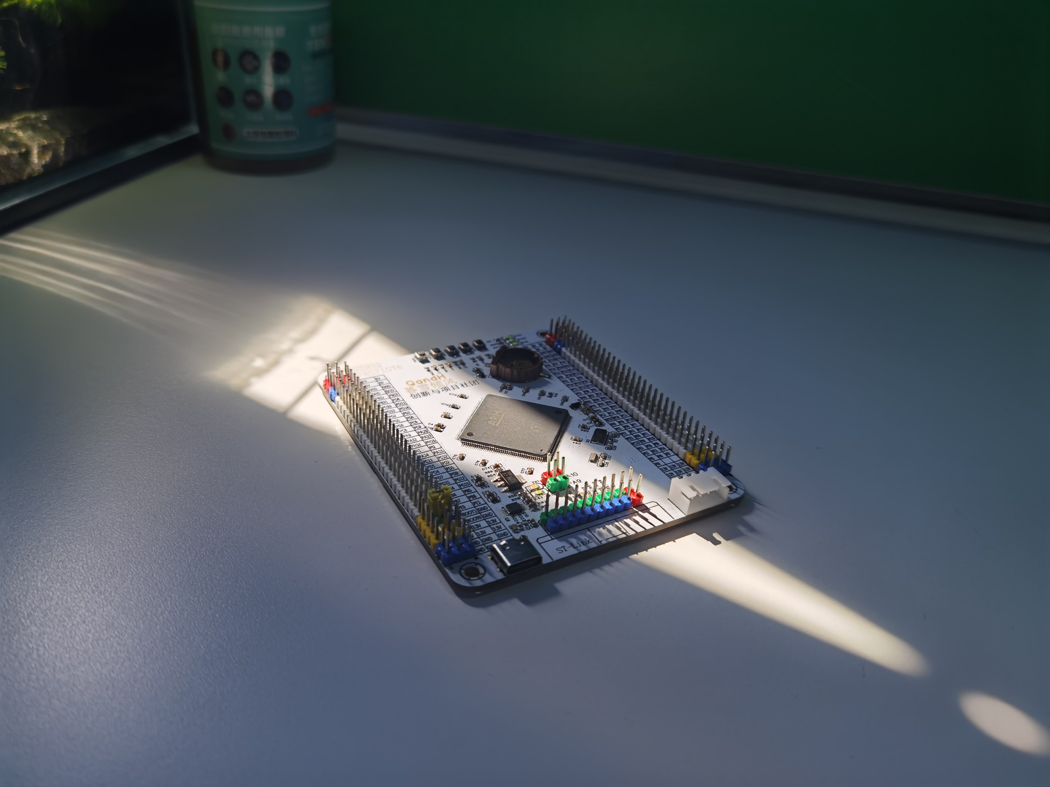
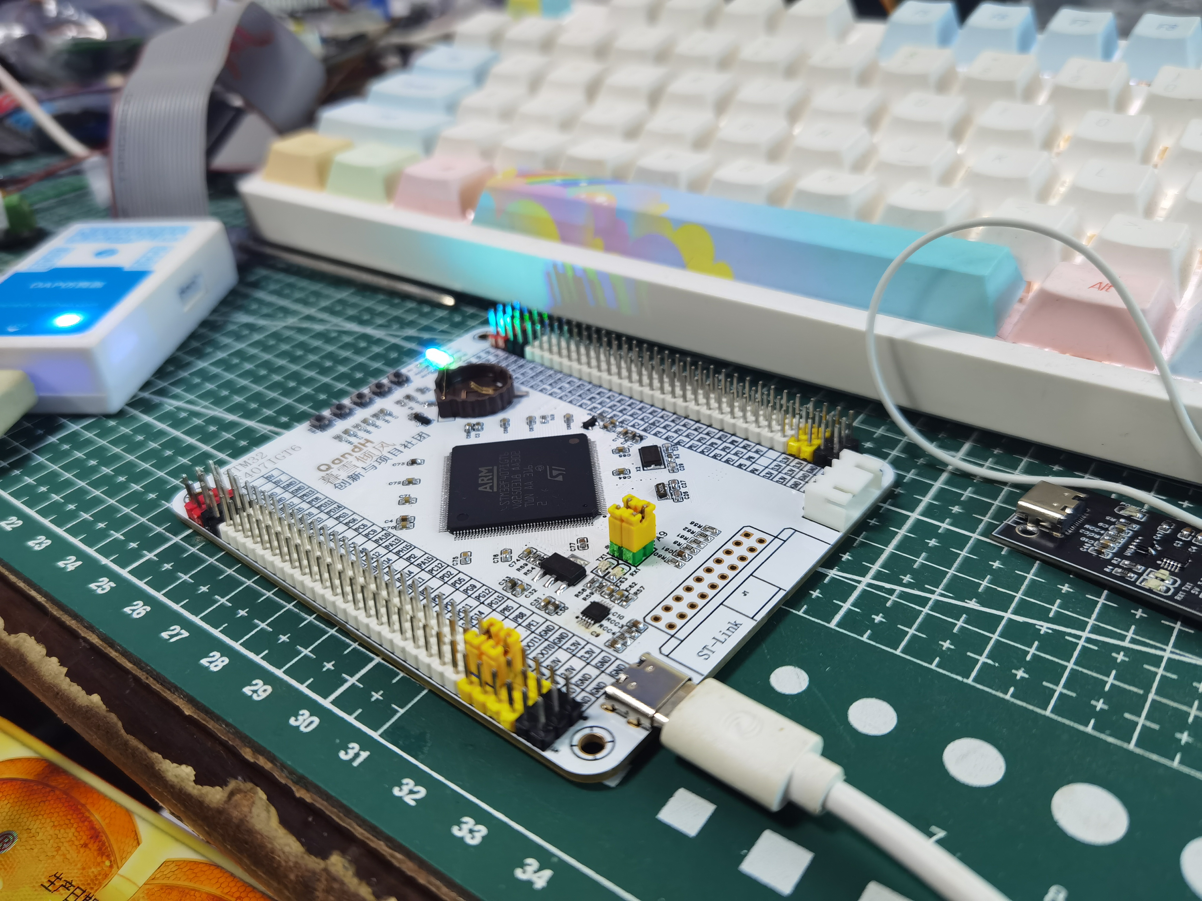
STM32F407IGT6 Minimum System Development Board - Color Silkscreen Printing
Color silkscreen version of STM32/GD32F407IGT6 minimum system development board
The functionality and layout are the same as the previous non-color silkscreen version.
(STM32F407IGT6 Minimum System Development Board
Image Gallery)


PDF_STM32F407IGT6 Minimum System Development Board - Color Silkscreen Printing.zip
Altium_STM32F407IGT6 Minimum System Development Board - Color Silkscreen Printing.zip
PADS_STM32F407IGT6 Minimum System Development Board - Color Silkscreen Printing.zip
BOM_STM32F407IGT6 Minimum System Development Board - Color Silkscreen Printing.xlsx
91642
Joule thief battery power drainer
Energy conservation and emission reduction start with me. Don't throw away old batteries! Using the Joule thief—a classic oscillating boost circuit—you can create a battery drainer that effectively utilizes the remaining battery power to make LED lights. This circuit is simple and easy to replicate, requires no microcontroller and no programming.
Project Introduction:
The Joule Thief can extract the maximum energy from a battery, even a seemingly "dead" old battery, allowing it to continue functioning. It's likened to a thief of electrical energy, a "joule." Its magic lies in the fact that an old AA battery, while seemingly empty, still retains about 1V. Since LEDs require 2-3V, the Joule Thief can boost this voltage, allowing the old battery to continue powering the LED. Project Functions:
1.
Can be used as an LED flashlight, providing light in the dark;
2. Further utilizes the remaining battery power, contributing to energy conservation and emission reduction;
3. Learns the classic Joule Thief oscillating boost circuit and masters related circuit knowledge.
Project Parameters:
This design uses a 5V battery box as the container for the low-power battery;
a 1KΩ resistor is used as a current-limiting resistor to provide current to the BE path of the transistor;
an NPN transistor is used, with a circuit voltage drop of approximately 0.7V. A
5mH common-mode inductor is selected as the key component (the inductance can be appropriately increased to enhance the boost effect);
an LED is used as the lighting circuit, with a measured turn-on voltage of 2.4V; a push-button switch is used.
Principle Analysis (Hardware Description):
When the switch is pressed and power is applied, current flows through the coil, providing a trigger signal to the base of the transistor, turning it on. Simultaneously, an electromotive force is generated in the inductor coil, hindering current flow. The current in the coil is insufficient to maintain transistor conduction, causing the transistor to turn off. The inductor
releases its stored energy, which, in conjunction with the power supply, generates a voltage higher than the power supply voltage, outputting pulsating DC to light the LED. Boost capability and load capacity are related to both the transistor and the coil.
The transistor continuously turns on and off, this process continuously cycles, generating a stable pulse output. Due to the afterglow effect of the human eye, there is actually no flickering sensation when viewing LEDs. Therefore, the battery drainer in this project can be used as a flashlight.
Related Reference Links 1
Related Reference Links 2
Related Reference Links 3
Software Code
This project does not have a microcontroller and requires no programming.
Notes:
When soldering, first use a hot air gun to solder the surface-mount resistors and LEDs, then solder the through-hole components;
when the circuit is connected and oscillating to boost the voltage, the inductor will produce high-frequency noise, proving that the circuit is working properly.
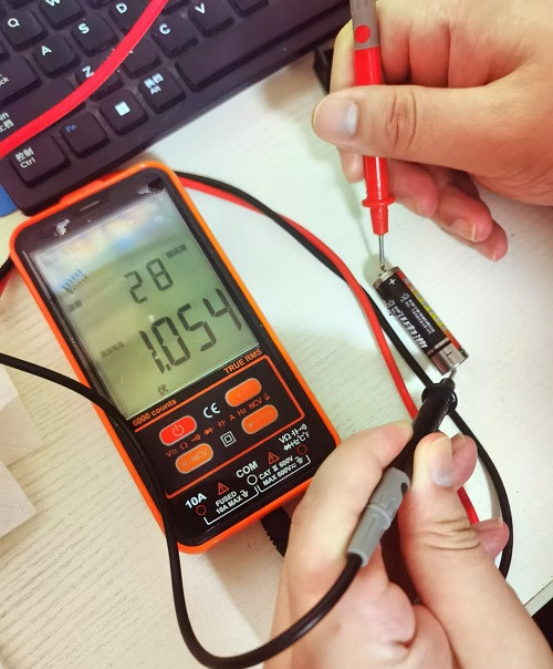
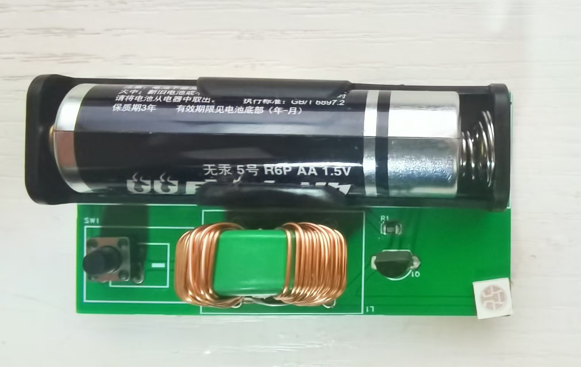
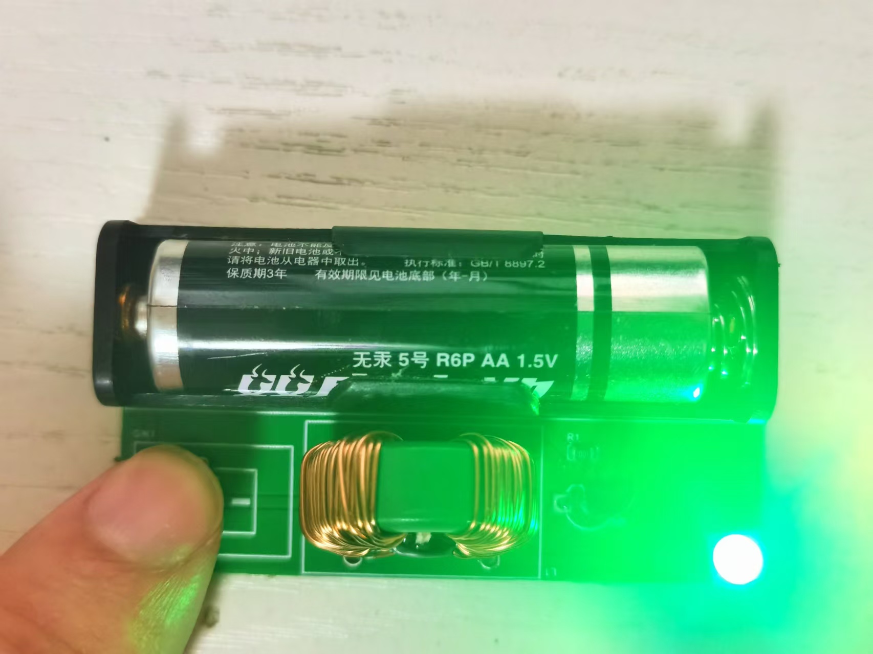
Actual Component Image
Measured Old Battery Voltage: 1.054V
Switch Not Closed:
Switch Closed:
PDF_Joule Thief Battery Power Drainer.zip
Altium_Joule Thief Battery Power Drainer.zip
PADS_Joule Thief Battery Power Drainer.zip
BOM_Joule Thief Battery Power Drainer.xlsx
91644
electronic


 京公网安备 11010802033920号

 MS1-B-14-250-2-1AB-A-A


