I. Project Background
Participated in JLCPCB/LCPCB Open Source Hardware Platform/JLCPCB EDA activities: Simple Oscilloscope Training Camp, and replicated the simple oscilloscope based on OSHWHub.
OSHWHub Simple Oscilloscope (Plug-in Version) Open Source Address
Hardware Parameters:
(1) AC/DC input;
(2) Low voltage range measurement range: -1.6V~5V, high voltage range measurement range: -80V~250V;
(3) Single channel;
(4) Input signal VPP measurement and Fre measurement;
(5) PWM output channel, adjustable duty cycle;
(6) Human-computer interaction (including TFT, LED*n, KEY*n, EC11, etc.).
II. Replicated Extended Specifications
Simple Oscilloscope (Replica Version) Open Source Project Address
Hardware Parameters:
(1) AC/DC input;
(2) Low voltage range measurement range: -1.6V~5V, high voltage range measurement range: -80V~250V; slightly different
(3) Dual channel;
(4) Input signal VPP measurement and Fre measurement;
(5) PWM output channel, adjustable duty cycle; Add MOS switch to allow current-sensitive loads to use PWM voltage regulation;
(6) Human-machine interaction (including TFT, LED*n, KEY*n, EC11, etc.);
(7) Connect to MDAQ module to expand data acquisition function;
(8) Operational amplifier negative voltage is generated by TPS65135, which can be adjusted by feedback resistor;
(9) LED is changed to RGB;
(10) Add SDCard;
(11) Add onboard CH340, enable UART-USB-DEBUG;
(12) Range adjustment is replaced by analog switch instead of toggle switch.
III. Hardware Design
This section mainly describes the design of the baseboard. Some related onboard modules will be omitted to avoid deviating from the topic.
For the purpose of replication, it is to facilitate beginners in the field of hardware product design, train the complete product design process, use the modular design concept, design the overall architecture based on the baseboard + expansion module board, and complete some performance improvements with surface mount devices.
In actual training, the parts that are needed are directly soldered/connected, and the parts that are not needed can be kept for future use without processing.
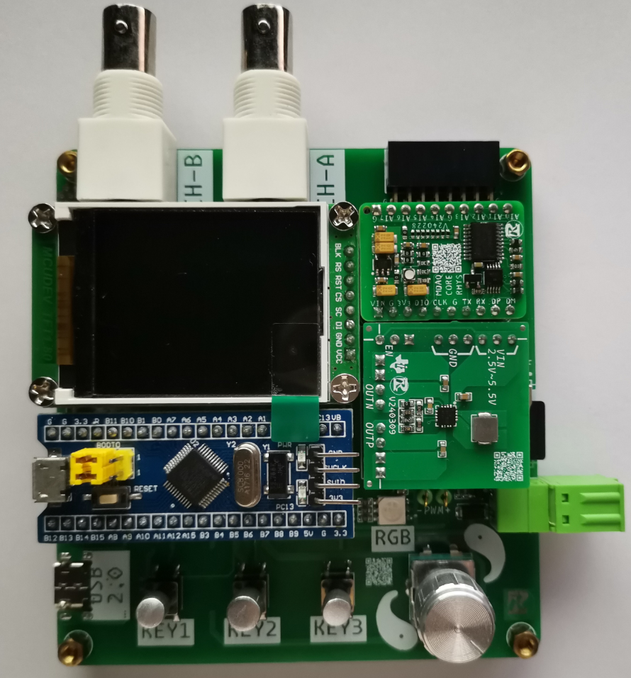
The finished product design is laid out as shown in the figure:
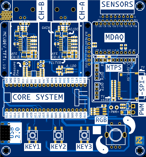
(1) All interactive parts are laid out on the top surface; among them, the buttons and other components that need to be operated are placed in the lower position, the TFT display screen is placed in the middle and upper position, and the interface for accessing signals is placed on the upper edge;
(2) The motherboard power supply is placed on the bottom surface using surface mount;
(3) The operational amplifier and other analog parts are hidden under the TFT screen;
(4) In addition to power supply, the USB-TYPE-C also has UART, which is connected to PA9/PA10 of the core board, corresponding to the peripheral USART1;
(5) Reasonable silkscreen instructions are provided.
The official documentation provides a more professional explanation than that of the copyist (me) regarding the relevant hardware design. See:
https://www.yuque.com/wldz/jlceda/dso.
The following only explains the different parts. For the same parts, please refer to "202: Simple Digital Oscilloscope Project Document".
(1) SCH_P2_POWER

1> CC1/CC2 pull-down, satisfying UDF, can be powered from PC or other sources;
2> TYPE-C interface uses 16P, with forward and reverse connection, USB2.0, and VBUS functions;
3> Add ESD protection circuit to protect power supply and signal lines;
4> Add fuse, current limit 0.5A, to prevent special accidental damage to PC USB port; (The measured current of this system is 100mA during normal use and 150mA at full brightness TFT)
5> Add power supply pre-filter and interface ground isolation. (Please note that capacitors here can easily affect startup time. If you have specific requirements for this parameter, please choose to solder smaller capacity capacitors.)
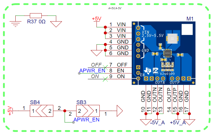
The positive and negative power supplies of the op-amp use a dual-rail power supply scheme based on the TPS65135 (because the op-amp I used required power supply limitations, the actual output was adjusted to ±3.5V).
This module is designed strictly according to the chip's recommended application examples. If you need to replicate this project or need this module, you can refer to the TPS65135 datasheet or contact me for relevant information.
Additionally, the baseboard is used for the APWR_EN pull-up, and this pin can also be used to detect whether the module is connected.
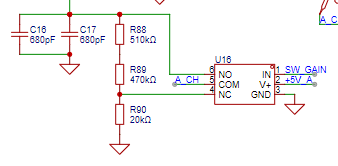
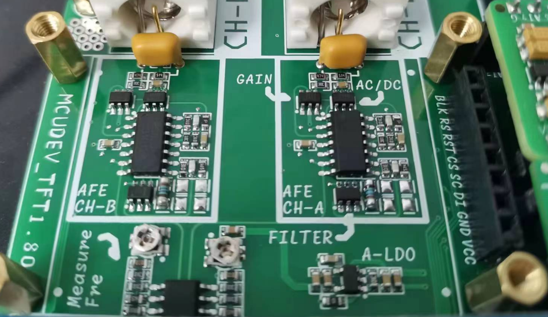
(2) The SCH_P3_AFE
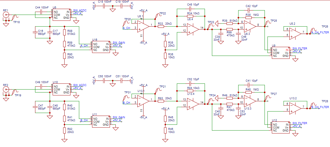
signal conditioning circuit uses CV. As you can see, the hardware design of CHA and CHB is exactly the same.
1> The gear adjustment uses analog switches instead of RS2103, which is a common single-pole double-throw (SPDT) switch.
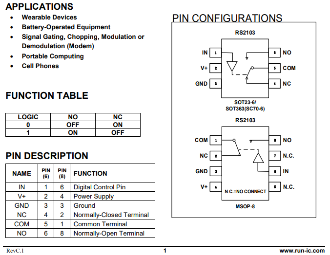
In its datasheet, through the truth table, we can know that when the user inputs different logic levels, NO or NC will be closed respectively.
2> There is one more capacitor (C16/C47) than the original circuit. This is a special package. I hope to use it to beautify the circuit or the signal.

3> By the way, you should be able to see from the figure that I have replaced the test points with surface mount ones. The main consideration is to save space.
4> Another reason for deciding to expand to dual channels is that the LM393 comparator has two channels inside. This makes full use of them.

In addition, I added potentiometers (R86/R87) here. They are used to fine-tune the hysteresis comparator threshold. If fine-tuning is not required, they can be left unsoldered.
(3) SCH_P1_CORE

At this point, almost all the pins on the core board are used, with different colors highlighting different blocks;
1> TF Card Module

TF cards are also called SD cards. Common communication methods include (SPI and SDIO). I am using a small card and using SPI communication for data reading and writing;
2> TFT Module (1.8-inch Display)
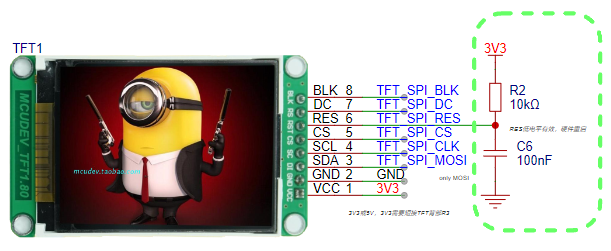
Because of budget constraints, I had to use whatever I had. Therefore, the pinout of this TFT is inconsistent with the TFT used in the official reference project. Please pay special attention!
3> Button Section:
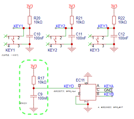
The button section has added a hardware filtering part, reducing the pressure on the code;
4> MDAQ Module:
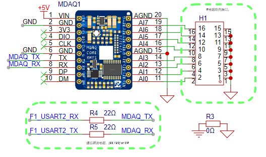
This is a small acquisition module that I made for the first color PCB project. It uses the MCU's internal ADC, with a precision of 12 bits, 8 channels, and an onboard serial communication chip.
Here, it is connected to the TX/RX of the core board through the RX/TX pin, which is actually connected to PA2/PA3 (i.e., USART 2) of the core board;
5> PWM Stepless Voltage Regulation:
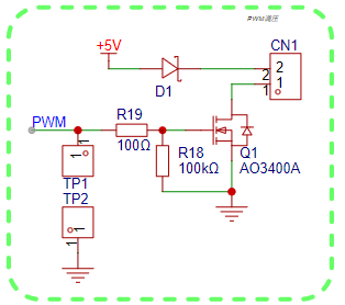
This is a very common and simple PWM voltage regulation circuit, suitable for current-sensitive loads such as heating wires and constant voltage LEDs;
6> UART to USB circuit based on Nanjing Qinheng CH340:
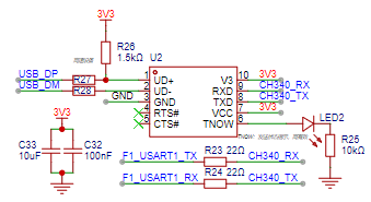
Due to the need for frequent code debugging, it is inconvenient without serial port logging. Therefore, this chip and its peripheral components were added.
IV. Software Design
Tips: This section only provides in-depth explanations of some parts of the software code. Routine operations will be omitted here. If you encounter any problems, please contact the author for discussion.
(1) Hardware driver debugging

Before the overall program design, it is necessary to debug the drivers of each hardware part to ensure that each hardware part works normally as designed.
I will start from the simple part and gradually introduce the driver debugging process:
1> GPIO
GPIO debugging is divided into RGB and RS2103, because they are actually OUTPUT functions of GPIO:
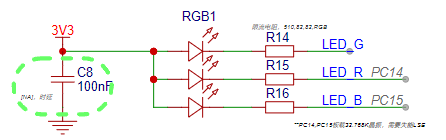
In the schematic diagram, I can see that the RGB driving situation is:
0
Light up
logic low
1
Turn off
logic high
First, do a simple define mapping,
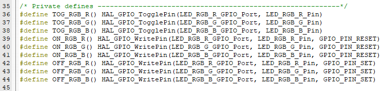
and then write some simple functions for initialization and integration testing.

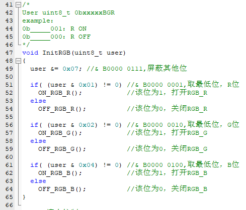
The following only introduces the initialization function:
For the RS2103 driver part, the same steps are followed. Before this step, the truth table is corrected:

define mapping,

initialization function

2> EXTI (KEY)
This is mainly the driver of the button part. Before the code is explained, the hardware configuration is explained:
Button name/chip pin
GPIO MODE
Pull-up/Pull-down
interrupt line (NVIC)
priority (you can choose)
KEY1/PB3
EXTI---Falling Edge
LINE3
KEY2/PB4
EXTI---Falling Edge
LINE4
KEY3/PB5
EXTI---Falling Edge
LINE[9: 5]
KEYA/PB6
EXTI---Falling Edge
Pull-up
LINE[9: 5]
KEYB/PB7
Input mode
Pull-up
KEYD/PB8
EXTI---Falling Edge
LINE[9: 5]
Here, the author designed a pseudo-thread for key events to record key actions and trigger responses in the main thread.
The roles of each bit in KEY_EVENT are:
BIT 8
BIT 7
BIT 6
BIT 5
BIT 4
BIT 3
BIT 2
BIT 1
X
X
Reverse
Forward
KEYD
KEY3
KEY2
KEY1
In main.c, void HAL_GPIO_EXTI_Callback(uint16_t GPIO_Pin)

points to void EXTI_Callback_2_EVENT(uint16_t GPIO_Pin) is used to map to the corresponding EVENT:
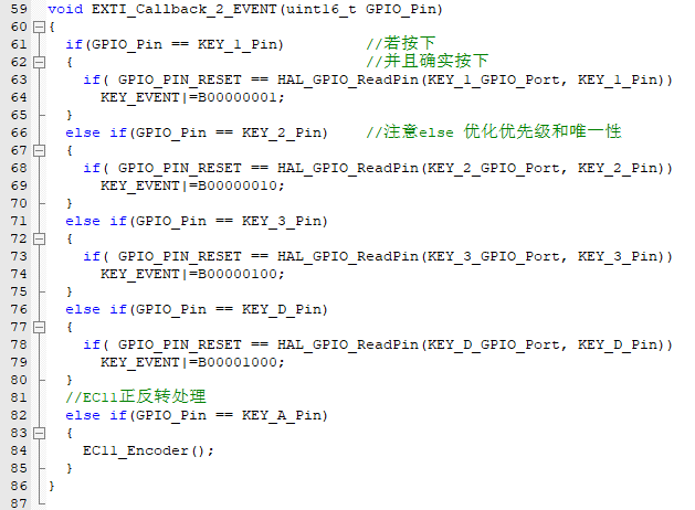
Forward and reverse involve the encoder and need to be handled separately, pointing to void EC11_Encoder(void)
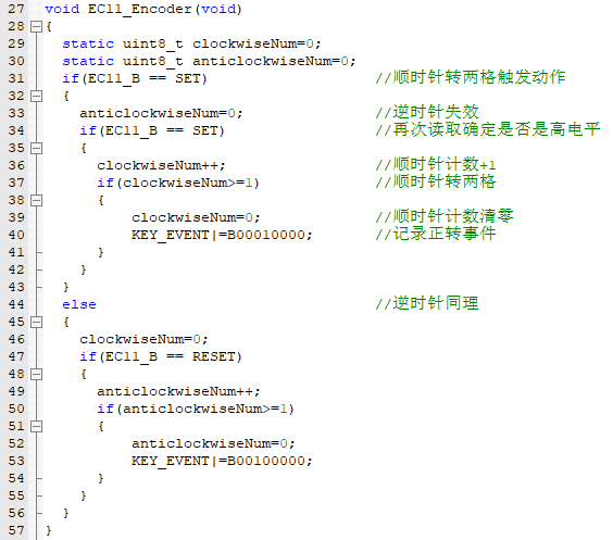
where EC11_A and EC11_B are defined and mapped macros:

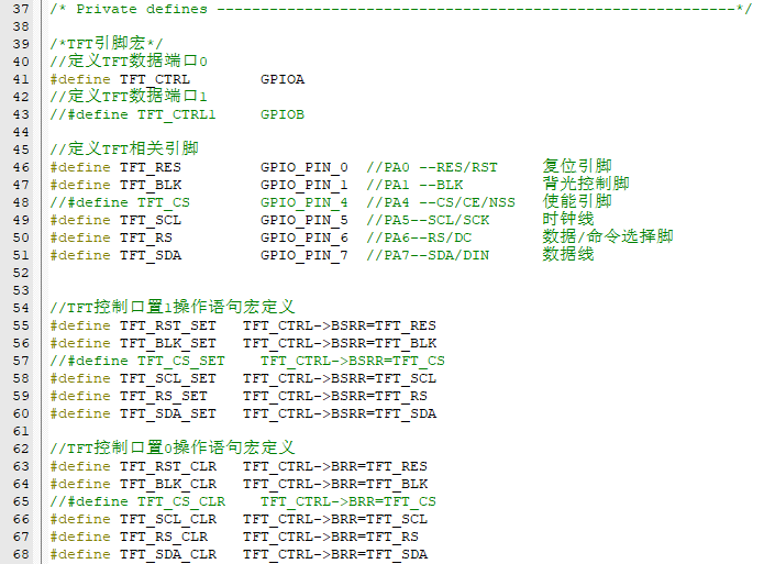
3> TFT (SPI1)
control of the display screen. The author referenced most of the code in the example, but made minor local modifications due to some differences to adapt to the hardware used:
Chip pin
purpose/multiplexing function
details
PA00
RES/RST
reset control
PA01
BLK
backlight control
PA04
CS/NSS
SPI hardware enable
PA05
CLK
SPI clock line
PA06
DC
command/data instruction switching
PA07
MOSI/SDA
SPI data line
According to the hardware connection, write the corresponding defined macros to facilitate the porting of TFT related functions:
It should be noted that the author enabled the hardware SPI1 NSS and OUTPUT to automatically enable CS according to the HAL underlying layer. Therefore, in many codes, the author omitted the processing of the CS pin.

Many examples and manufacturer-provided ST7735S drivers are almost compatible with both software SPI and hardware SPI, and have strict control over data bits. To simplify the code and facilitate learning SPI-TFT control, I've optimized the code.
SPI control can vary significantly depending on the HAL library API, so I first encapsulated the SPI read/write functions:
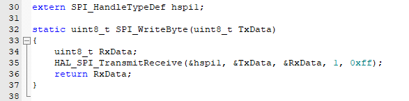
(It's important to note that HAL_SPI_TransmitReceive() is superior to writing 8 bits of data at a time. For writing 16-bit data frames, refer to my subsequent approach, which is simpler and avoids rewriting a dedicated function for sending 16-bit data frames.)
Next, I rewrote the two lowest-level TFT operation functions (TFT_WR_REG) and (TFT_WR_DATA). These functions are used during initialization of almost all TFT functions
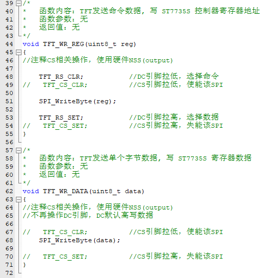
. Since my ST7735S seems to sometimes disregard the initialization sequence, often resulting in screen flickering after writing the initialization sequence,
I haven't found a complete solution to this display issue. Therefore, before initialization is complete, I turn off the backlight, refresh the screen to a black screen, and then turn the backlight back on:

For other functions, let me think about what aspects CV engineers need to pay special attention to. Hmm, it's here:

For example, this specified area filling function. The example shows sending a 16-bit data frame, but I've already selected an 8-bit frame when initializing SPI1. What to do?
That's right, as in (r322/r323), send it twice. Sending it twice solves the problem, saves a function, reduces program coupling, and makes the code easier to read and understand!
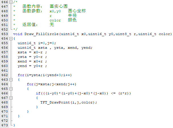
For one of the functions, I need to draw a solid circle. Here's the relevant code, using the standard circle equation x^2 + y^2 = r^2.
Based on this formula, I check in the function whether a point is inside the circle. If it is, I draw the point to achieve the effect of drawing a solid circle.
To ensure compatibility with both CHA and CHB dual-channel rendering, I rewrote the rendering function in the example (mainly modifying the number of channels and rendering position, and fixing a bug to make the refresh more seamless).
Pay attention to these parameters, as dual-channel rendering requires two permanent buffers to store information from the previous point; this is the biggest difference from single-channel

rendering. Dual-channel simultaneous display also requires adjustments to the display position.

Secondly, the original single rendering is replaced with double rendering.
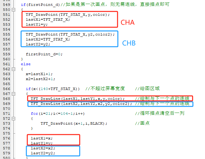
For better display, the original example code might have residual images from the previous round due to display issues during a new round of display; a double clear is performed here.

There are no other points to note; dual-channel rendering is now complete. Finally, it must be said that this older ST7735S model has a ridiculously high offset; it's best to buy a brand new model if possible.
Regarding offset, you can refer to my work for minor adjustments, which can be seen in the full-screen clear function. This is how I handled the offset issue. Of course, you can also use the method of increasing the drawing area to make up for the offset area.

4> SDCard (SPI2)
chip pin
uses/multiplexing function
details
PB12
CS/NSS
SPI hardware enable
PB13
CLK
clock line
PB14
MISO
data line SDI
PB15
MOSI
data line SDO
This driver is a bit complicated. In fact, if it weren't for the capacity limitations of the STM32F103C8T6, I would recommend using the middleware-based FATFS approach, as HAL has built-in compatibility. However, adding other modules would make this middleware too large, with insufficient RAM and ROM for a full compilation.
As a last resort... well, not the worst option, I ported it according to the official documentation:
[FATFS Open Source FAT File System Module Official Website]
. From the official website, I obtained the FATFS source code. The latest version is R0.15, but it seems to have increased in size. I lowered it to R0.09, which is more stable and smaller.
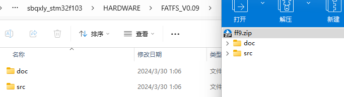
I unzipped it and placed it in the project path, then rebuilt diskio.c under src, implementing several functions
: `DSTATUS disk_initialize (BYTE); //SDCard InitDSTATUS disk_status (BYTE); //get SDCard statusDRESULT disk_read (BYTE, BYTE*, DWORD, BYTE);//read SDCardDRESULT disk_write (BYTE, const BYTE*, ... DWORD, BYTE);//write SDCardDRESULT disk_ioctl (BYTE, BYTE, void*);//get SDCard info
Implementation thanks to various forums, open-source websites, and experts. The cv process will not be described here, and I certainly recommend that everyone type it by hand. -- If time permits,
in addition to the .c file independent of the HARDWARE folder, other peripherals used also need to be configured:
5> DEBUG USB2.0 (USART1)
Redirection three steps:

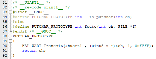
Then you can happily printf();
6> MDAQ (USART2)
Here, interrupt reception is used, idle indefinite-length interrupt reception, and data integrity is verified by handshaking with MDAQ:
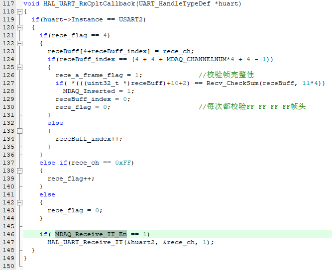
Since I have not yet established the NVIC priority order, if not in the MDAQ display interface, I control the interrupt enable of USART 2 through the MDAQ_Receive_IT_En bit.
Simply put, if not in the MDAQ interface, USART interrupt is not allowed, so as to avoid interference with other program interrupts, thereby preventing the related processes of the bare metal program from being blocked.
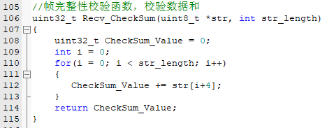
Since the MDAQ data protocol is custom-defined, the author added a checksum mechanism at the end to verify the integrity of the transmitted data frame and prevent data corruption due to frame loss.
7> Oscilloscope channels A/B (ADC+DMA)
CHA/CHB acquisition correspond to the hardware ADC1-IN8 and ADC1-IN9
chip pin
uses/multiplexing functions.
Specific descriptions:
PB00
ADC1-IN8
sampling channel CHA
PB01
ADC1-IN9
sampling channel CHB
mode uses regular grouping, ADC_Regular_ConversionMode.
For sampling continuity, ADC+DMA is used, and the internal sensor and Vrefint are also directly used. The CPU temperature and sampled voltage are polled together.
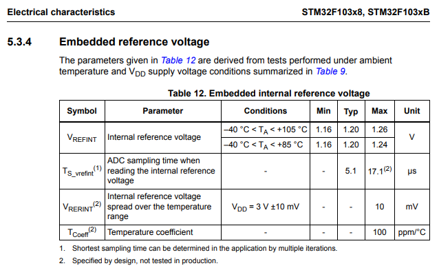
It's important to note that the Vrefint channel is used for sample verification and is particularly crucial. A slightly longer sampling period is recommended for stability. Here, all channels used the longest possible sampling period for more accurate sampling.

In DMA, the system moves the sampled value to a specified cache, but it stores the corresponding (12-bit) 4096 value. Therefore, it needs to be converted to voltage. A function is encapsulated here to specifically map the sampled 4096 value to voltage or temperature.
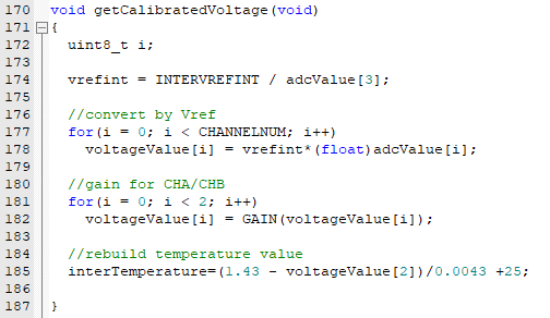
Simultaneously, due to signal amplification, attenuation, and offset conditioning in the AFE circuit, there is a deviation between the ADC sampled value (Vadc) and the actual detected value (Vin). Therefore, Vin needs to be calculated back based on the hardware circuit.
My hardware circuit involves three instances of this back-calculation:
If a /1 gain is selected, then Vo = Vi;
if a /50 gain is selected, then Vo = Vi * 20 / (510 + 470 + 20).
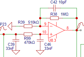
If the filter setting is selected, then Vo = (1+1M/510k)*Vi.
If the pass-through setting is selected, then Vo = Vi.
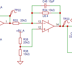
This is the most important part, the configuration of the sample, which is always enabled, so a reverse calculation mapping must be done:
If the configuration in the diagram is as shown, then Vo = (5-Vi) *2.
However, the author did not actually have a +5V input, but rather +2.97V, so two hardware parameters were adjusted:
Component number,
original configuration,
author's configuration:
R33
20kΩ
50kΩ
, R35
20kΩ
15kΩ.
Therefore, Vo = 1.44 - 0.2*Vi. This is the theoretical calculation formula. Oh,
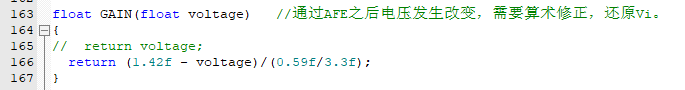
some people might ask again, isn't it Vo = 1.44 - 0.2*Vi? The calculated Vi = (1.44 - Vadc) / 0.2, so how come the actual programming becomes the one in the diagram?!
1.42f is the actual measured V+ boost voltage;
0.59f / 3.3f is the standard voltage input, and the resulting α value (gain).
With an input Vi = 3.3V
and a measured Vadc = 0.83V
, α can be calculated using the theoretical formula: 0.83 = (1.42 - α*3.3)
, resulting in α = 0.59 / 3.3 = 0.17878787878...
Because it's an infinite decimal, we directly substitute α = 0.59 / 3.3 into the original theoretical formula.
The final corrected and calibrated inverse calculation formula is: Vi = (1.42 - Vadc) / (0.59 / 3.3).
To prevent optimization during compilation, 'f' is added to force the data to be of float type, avoiding optimization calculations and ensuring the output is calculated according to the predetermined inverse calculation.
8> Frequency measurement channel A/B (TIMER - Input Capture Mode)
measures frequency using the hysteresis comparator circuit in the AFE schematic. The official example explains the specific principle more thoroughly than I understand it, so I won't elaborate further.

In some differences, R86 is an extra component used to fine-tune the hysteresis comparator's threshold; it can be left untouched.


[This diagram is from https://www.yuque.com/wldz/jlceda/ga83zq8s4b55hpqm]
In terms of hardware configuration,
the chip pin
multiplexing functions
correspond to the following channel
modes :
PB10
TIM2_CH3
CHA-FRE
Input Capture direct mode;
PB11
TIM2_CH4
CHB-FRE
Input Capture direct mode.
[Let me first point out the shortcomings of my algorithm. The shortcoming is that it cannot calculate the duty cycle because I simply set all capture interrupts to be triggered on the rising edge.]

Furthermore, my algorithm doesn't specifically address this. If you need to calculate the duty cycle, you can use a combination of switching the trigger edge and double capture to calculate the duty cycle
. The specific algorithm is roughly as follows: capture twice, keeping the trigger edge the same, capture twice consecutively, and calculate the difference. This difference is the captured period.

We know that Fre = 1/period
, assuming Fre's unit is Hz and period's unit is
seconds. The specific period unit is not seconds, but 1/(clock frequency/prescaler + 1).
Here, we use HAL_RCC_GetHCLKFreq() to obtain the CPU clock frequency (72MHz), and the prescaler is (72-1). Therefore, the timer counting period is 1/(72MHz/72) seconds.
The final calculation formula is: Fre = HAL_RCC_GetHCLKFreq()/72/(capture2 - ... Similarly ,
CHB is calculated in the same way, but it should be noted that a new buffer needs to be defined statically: capture3, capture4, frequency2.
9> PWM Output Channel (TIMER--PWM Mode)
PWM uses hardware PWM output. The STM32F103C8T6 has an internal PWM peripheral, corresponding to PB9------PWM Generation. CH4
uses PWM mode 1.
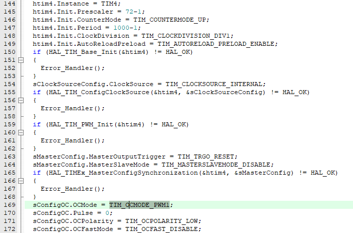
As for the principle of PWM, this diagram is particularly good: (In particular, in the diagram, less than Vth is OCPolarity, which I set to LOW for low polarity).

In order to adjust the PWM output frequency and duty cycle in the program, two functions need to be written:

10> System Running Time (TIMER--ClockInterrupt)
This is a general timer used for testing, set to TIM1, 1ms, interrupt once. It is too simple and common, so I won't explain it here.
(2) Application Programming
1> APP (Static Interface)
The static interface is a function that only needs to be operated once for the first time under different modes. Its function is to write the background of the display interface.
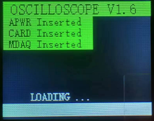
***Loading Interface***
**keyword: Module detection, progress bar**
>>>S1 Clear screen to ensure the screen is clean
>>>S2 Draw title
>>>S3 Draw simple progress bar
>>>S4 Module detection (APWR, MDAQ, SD_Card)
>>>S5 Force jump to oscilloscope interface
Segment display:

Actual interface:
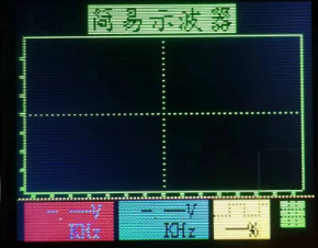
***Oscilloscope interface***
**keyword: Initialize oscilloscope interface**
>>>S1 Clear screen to ensure the screen is clean
>>>S2 Draw title
>>>S3 Draw coordinate system, grid lines
>>>S4 Draw initial parameter position, initial parameter assignment
Segment display:

Actual interface:
***Acquisition card interface***
**keyword: Initialize acquisition card interface**
>>>S1 Clear screen to ensure a clean screen
>>>S2 Draw title
>>>S3 Draw coordinate system and grid lines
>>>S4 Draw initial parameter positions, assign initial parameter values, and channel prompt button
. Example:

Actual interface:

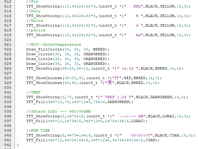
***Background Interface***
**keyword: Initialize background interface**
>>>S1 Clear screen to ensure a clean screen
>>>S2 Draw PWM related initial parameter positions, assign initial parameter values, square wave LOGO, etc.
>>>S3 Draw temperature, temperature LOGO, temperature unit, etc.
>>>S4 Draw internal reference voltage, SD card initial parameters, and running time initial parameters.
Example:
Actual interface:

2> APP (Running Interface)
The running interface is the continuously running function after the static interface.
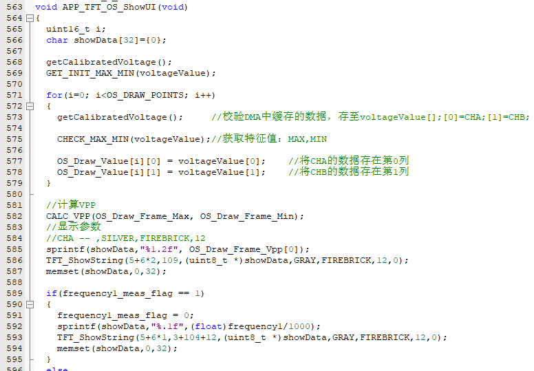
***Oscilloscope Interface***
**keyword: Oscilloscope voltage, frequency continuous detection, duty cycle real-time adjustable and switchable**
>>>S1 Assign initial values (including VPP/MAX/MIN)
>>>S2 Get display length CHA and CHB
>>>S3 Calculate VPP/MAX/MIN
>>>S4 Plotting parameters VPP/FRE
>>>S5 Plotting curve
segment display:
Actual interface:

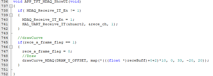
***Acquisition card interface*** [Semi-complete] The author only plotted CH1
**key word: acquisition card curve plotting**
>>>S1 Initial value assignment (including VPP/MAX/MIN)
>>>S2 Get display length CHA and CHB
>>>S3 Calculate VPP/MAX/MIN
>>>S4 Plotting parameters VPP/FRE
>>>S5 Plotting curve
segment display:
Actual interface:

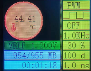
***Backend interface***
**key word: CPU temperature, internal reference voltage, SD card attributes, system runtime, PWM related parameters**
>>>S1 Calculate and assign internal CPU temperature
>>>S2 Calculate and assign internal reference voltage
>>>S3 Calculate and assign system runtime
>>>S4 Calculate and assign SD card attributes
>>>S5 Calculate and assign PWM related parameters
Segment display:

Actual interface:
3> APP (passive interaction)
mainly refers to plotting or data refreshing.
When the user does not perform any active operation, the system should run stably in the corresponding mode. The functions I mentioned above only refresh the entire screen once, so a top-level function is needed to schedule these SHOW functions:

In the main function, you only need to call the UI_Run_Switch() function;

if frequent refreshes are not required, you can increase the delay slightly.
4> APP (Active Interaction)
mainly refers to button operation and event response.
Pay special attention to the priority here. From top to bottom, the priority is from high to low. This is easy to understand. It is the order of running decisions .

I have many preset functions that I did not have time to put on the releaseV1.89 version,
such as EC11 knob--->switch selected blocks;
such as EC11 button--->confirm entry function;
such as PWM Fre can be modified;
such as grid display or not;
... ...
I left some of these related tests in part.

V. Review of the main thread architecture
Overall design scheme
In the main function process, it is necessary to reuse and initialize the relevant enabled peripherals:

it is also necessary to enable various peripherals, initialize the modules, and load the interface:

then enter the while(1) loop of the main thread to perform the above active/passive interaction:

VI. Physical display
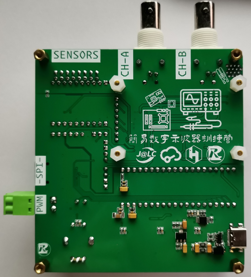
Complete front, back, AFE partial front
soldering reference
Back soldering reference
AFE partial selection soldering reference
VII. Demonstration video
Tip: Demonstration video, test the above functions, and upload the source code in the attachment. It is too big, see the link.
【LCSC Training Camp】Simple Oscilloscope https://www.bilibili.com/video/BV1zm41167ri/?share_source=copy_web&vd_source=5d12763b5ade8bc59d748a8f28a5d25e
VIII.
Notes: The code is for reference only. Please note the open-source license. For cooperation, please contact the author.
IX. Attachment Contents
: releaseV1.89 is the version used in the author's test demonstration video. Attached firmware: releaseV1.89_.hex Attached project: releaseV1.89_.zip


 京公网安备 11010802033920号

 177-710-2-51CS6K7-24PDN


