project uses an ESP32 microcontroller as the main control and communication module. It utilizes the Diandeng Technology IoT platform, employing Wi-Fi to remotely control a servo motor to pull the lock, achieving remote door opening.
, and an MG995 servo motor (an SG90 can also be used, depending on the lock's resistance). The required environment includes a
and a password-protected Wi-Fi network (the campus Wi-Fi is not acceptable).
. On-site demonstration:
(Powered from the dormitory Wi-Fi's USB port, or powered by a charger (a cheap and stable 5V 1A charger will suffice)).
[Adorable Newbie's Daily Mishaps with Remote Control] https://www.bilibili.com/video/BV1vj421S7ZF/?share_source=copy_web&vd_source=97d2780f4be264bcdcbdc136b63163f9

Loli New 6-Channel Receiver A.10.hex
Loli Remote Control_2024-01-31.zip
[Batch Download] Burning Options, etc. .zip
A certain robot.7z
PDF_Loli Remote Control.zip
Altium_Loli Remote Control.zip
PADS_Loli Remote Control.zip
BOM_Loli Remote Control.xlsx
95582
Intelligence Power Recharge Machine
IQ Power Recharge Machine:
Main Controller: STM32F103C8T6
; Display: 1.8-inch TFT color screen;
Monitoring: Heart rate and blood oxygen module (MAX30102);
Recharge Electrodes: WS2812B LED string.
1. Project Description:
To fit the theme of amusement, a machine was specially created that can "recharge" human intelligence and strength.
It is hereby declared that the "Intelligence and Strength Recharge Machine" is purely for entertainment and has no health or medical benefits whatsoever.
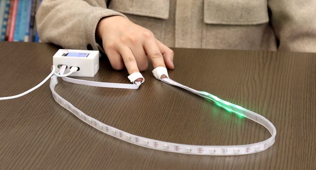
2. User Guide (Intelligence and Strength Recharge Machine_Bilibili_bilibili)
1. Place the sensor on your finger or wrist to collect intelligence and strength values. Wait for the specific values to be displayed on the screen.
2. Set the intelligence or strength data to be recharged on the screen, install the recharge electrode, and then click "Start Recharge."
Note: Do not remove the sensor during recharge. Excessive recharge may cause discomfort. The system will monitor your body indicators in real time. If any discomfort is detected, the system will immediately stop recharge and observe for 1-3 seconds before deciding whether to withdraw the recharged amount to prevent the body from being overwhelmed. Individual differences may occur.
3. Once the system indicates that recharge is complete, you can remove the recharge electrode and sensor.
After being recharged, you'll feel refreshed:

During recharge, heart rate and blood oxygen levels are monitored, and the recharge progress is displayed:

During recharge, be sure to wear the recharge electrode and monitoring electrode properly:
Recharge successful:

Recharge failed:

For a detailed demonstration, please watch the video: IQ Power Recharge Machine_Bilibili_bilibili
Software open source address: Jgcoder2023/iq: IQ Power Recharge Machine (Yule) (github.com)
Technical solution:
Main controller: STM32F103C8T6
Display: 1.8-inch TFT color screen
Monitoring: Heart rate and blood oxygen module (MAX30102)
Recharge electrode: WS2812B LED string
PDF_Intelligence Power Recharge Machine.zip
Altium_Intelligence Power Recharge Machine.zip
PADS_IQ Power Recharge Machine.zip
BOM_Intelligence Power Recharge Machine.xlsx
95583
[Open Source] STM32F103C6T6 Minimum System Board
STM32F103C6T6 Minimum System Board
Unable to tolerate the haphazardly arranged I/O ports on system boards sold online, I decided to build my own with orderly arranged I/O ports. To be honest, it was quite difficult to design; I even considered building a four-layer board. I went through two or three rounds of complete deletion and redesign, but finally, it's finished (this might be no problem for experienced programmers).
This system board integrates a boot selection circuit, a CH340, and USB-to-serial communication. The USB interface uses Type-C, and the power supply uses an AMS1117 linear regulator. The orderly arranged I/O ports make peripheral circuit development and programming easier.
However, some parts are poorly designed. For example, without a jumper cap, the boot pin is floating, and some lines seem to circle the board before reaching the MCU, which is extremely unfriendly for communication. As for whether it has any impact, and how much, I haven't tested it, and I'm too lazy to fix it. I also wanted
to include the CH340 reset circuit, but there was simply no room on the board, and it wasn't necessary
to connect the PC3 pin to the LED next to the power indicator; it wasn't brought out.
PDF_[Open Source]STM32F103C6T6 Minimum System Board.zip
Altium_[Open Source]STM32F103C6T6 Minimum System Board.zip
PADS_[Open Source] STM32F103C6T6 Minimum System Board.zip
BOM_[Open Source]STM32F103C6T6 Minimum System Board.xlsx
95584
Nine-day environmental instrument
The Jiuri Environmental Analyzer is a small, portable environmental monitoring device. Currently, it is designed to measure temperature, humidity, air pressure, and harmful gas levels.
Its innovative features include: the use of 2.4G and 4G communication, a high-precision sensor, and an LVGL-based page design.
一、项目介绍
1.背景
我国目前的产业地区分布地域辽阔,地形复杂,导致工矿企业和乡镇企业分布很广,这给环境监测人员的监测工作带来很多的不便,环境监测人员不可能将大型的实验室检测设备运送至各处。尤其相当量的乡镇企业已经蓬勃兴起,但许多乡镇还没有具备检测的能力,在预防和治理的过程中有着很大的不便和患。便携式检测仪器的使用不仅可以减少环境式样在传输过程中的污染问题,减少样品固定和保存的繁杂手续,而且可以大大减少检测人员的工作量,实时掌握环境等动态变化趋势,从而尽可能地将潜在的风险降至低。因此需要设计一款基于梁山派的无线手持环境检测仪。
2.特点
九日环境仪是一款小技,携带方便的环境检测装置,目前设定的功能有测量温湿度、气压、有害气体的数值;该设备创新点:采用了2.4G,4G通信的方式,采用了高精度的传感器,3.使用了LVGL的页面设计。
3.采用的技术
I2C,USART,API通信协议,2.4g,4g无线通信技术,电路设计,原理图绘制,PCB设计,元件采购,焊接,LVGL界面设计等技术
二、整体设计框图

三、原理图设计
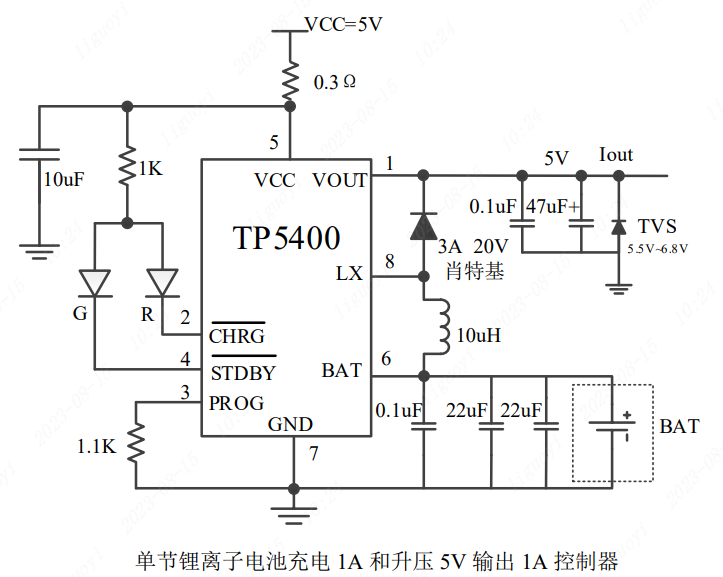
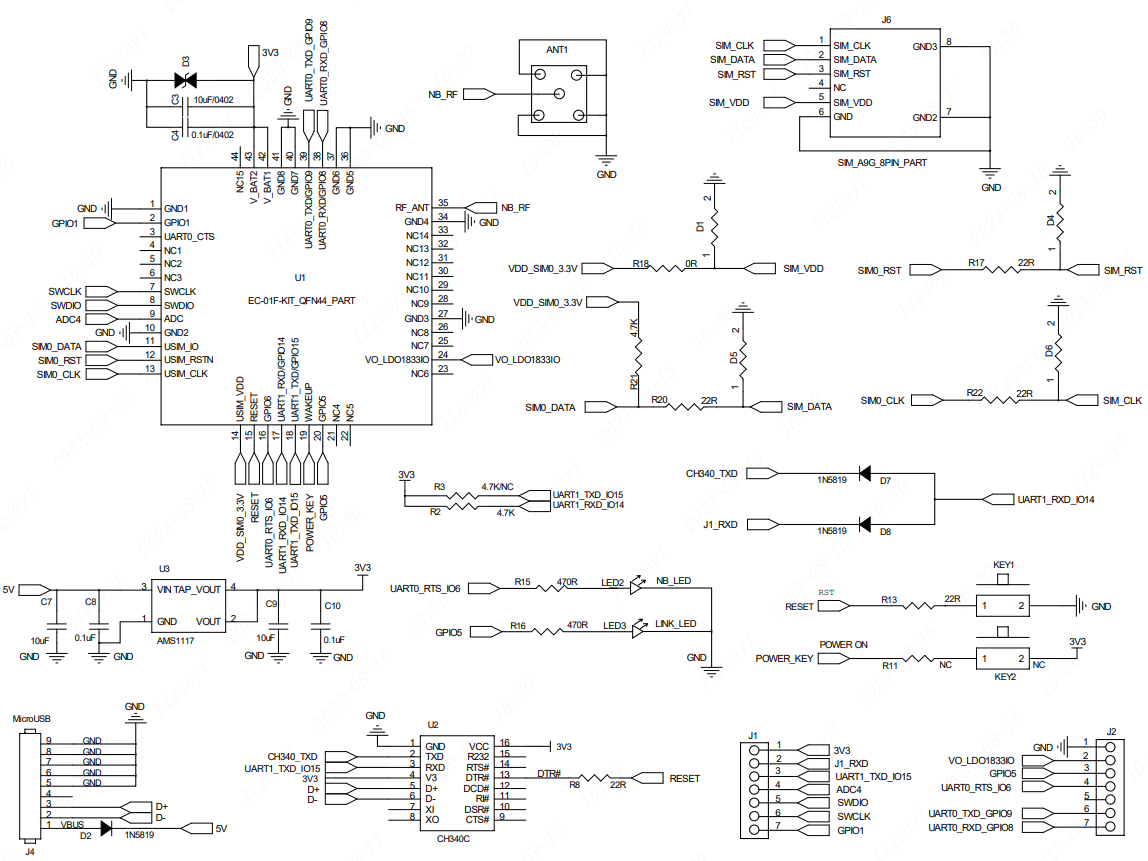
1.电源模块的电路设计:
该电路主要是根据芯片手册上的电路图实现的
TP5400 为一款移动电源专用的单节锂离子电池充电器和恒定 5V 升压控制器,充电部分集高精度电压和充电电流调节器、预充、充电状态指示和充电截止等功能于一体, 可以输出最大 1A 充电电流。
、

电池电压为 BAT+,Type-C充电电压为VCCIN,VOUT为5V输出电压。实际应用电路中,STDBY引脚未使用,该引脚为充电完成指示引脚,充电的时候我们亮一个灯(CHRG),表示正在充电;充电完成(STDBY)我们可以什么都不做,毕竟充电灯都不亮了,代表已经充满电了。
2.传感器模块的电路设计:
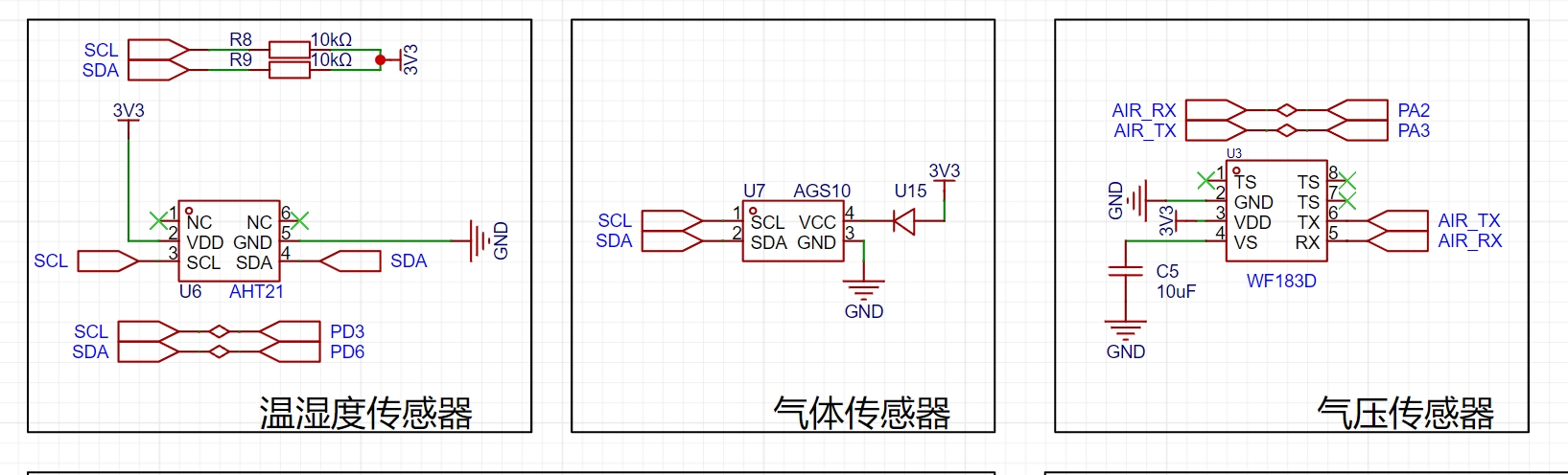
分别采用了AHT21温湿度传感器、AGS10气体传感器、WF183D气体传感器。
(1)AHT21作为新一代温湿度传感器,采用数字输出,I C 接口,有优异的长期稳定性,使用SMD封装适于回流焊并且响应迅速、抗干扰能力强,我们根据其电气特性可以知其输入电压应在输入电压为2.0~5.5V。
(2)气体传感器WF183D是一颗经济型数字压力温度传感器内部包含一个MEMS压力传感器和一个高分辨率 24位△∑ADC及DSP。WF183D通过UART提供高精度已校准压力和温度数字输出,通讯连接非常简单。它的数字压力温度直接读取
工作电压: 2.4V~3.6V压力量程: 0~180kPa(绝压)工作电流: 1.5mA待机电功耗:
(3)AGS10是一款采用数字信号输出的MEMS TVOC传感器。配置了专用的数字模块采集技术和气体感应传感技术,确保了产品具有极高的可靠性与卓越的长期稳定性,同时具有低功耗、高灵敏度、快速响应、成本低、驱动电路简单等特点。AGS10主要适用于侦测各类有机挥发性气体,如乙醇、氨气、硫化物、苯系蒸汽和其它有害气体,可应用在空气净化器、家用电器、新风机等设备。传感器采用标准IIC通信协议,适应多种设备。IIC的物理接口包含串行数据信号(SDA)与串行时钟信号(SCL)两个接口。设计时两个接口需通过1kΩ~10kΩ电阻上拉至VDD。
3.电路测量电路设计

因为GD32的IO口最大可以兼容5V,超过5V就会把IO口烧坏;而测量电压的外设ADC,它的参考电压在立创·梁山派开发板上是3.3V。所以如果使用ADC直接测量电池的电压,那么它无法测量3.3V以上的电压。
为了解决这个问题,我们可以通过电阻分压的形式测量电池电压。电阻的大小可以根据IO口电平计算,分压后不要超过IO口容忍的电压的即可,选取一个合适的值。这里我们选择最常用的10K电阻进行分压
4.屏幕的电路设计

该屏幕使用的是SPI通信方式,为了达到更快的刷屏效果,我们在选择连接开发板的引脚时,可以连接到硬件SPI引脚上。本案例连接的是PB3(SPI0_SCK)PB5(SPI0_MOSI)。
5.2.4G无线模块的电路设计
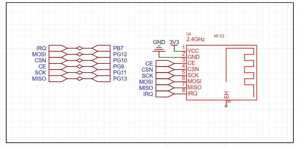
本方案采用的是NF-03 2.4G模块
2.4GHz频段是一种常用的无线通信频段,具有较好的穿透能力和较远的传输距离,适用于各种无线通信应用。该模块能够同时实现数据的发送和接收功能,提供了更方便的无线通信解决方案。具有高速数据传输可以满足大多数应用的需求,如传输音频、视频、图像等。低功耗设计:为了延长电池使用寿命或减少电源消耗,这种模块通常采用低功耗的设计,以提供更长的使用时间。
特点:简单易用:2.4G无线收发一体模块通常提供简单易用的接口和协议,方便用户进行配置和控制。这种模块可以广泛应用于无线遥控、无线数据传输、无线传感器网络等领域,为各种设备和系统提供稳定可靠的无线通信能力。
引脚说明CE 可以长期接高电平,但是模块写寄存器的时候必须设置为掉电模式,建议 CE 脚连接单片机的 GPIO 口;IRQ 可不接,可采用SPI 查询方式获取 STATUS 寄存器的中断状态。但建议使用单片机的硬件外部中断,让 IRQ 接单片机外部触发引脚,触发单片机中断;注意接地良好,有大面积的铺地,电源纹波小,应增加滤波电容并尽量靠近模块 VCC 与 GND;
6.4G模块的电路设计
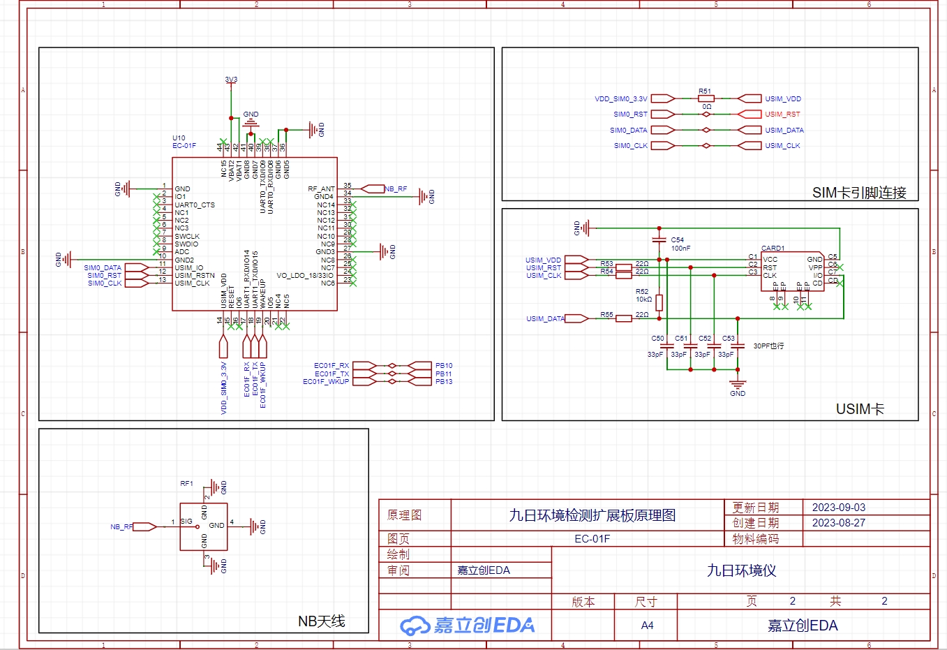
本方案采用的是EC-01FNBIOT模块,电路图也是根据芯片官方给出的电路图进行设计
NBIoT(Narrowband Internet of Things)模块是一种专门用于窄带物联网通信的硬件模块,它提供了一种省电、低成本、远距离通信的解决方案,适用于物联网(IoT)设备和应用。
以下是NBIoT模块的一些主要特点和功能:
窄带通信:NBIoT模块采用窄带通信技术,其优势是具有较低的功耗和较长的通信距离。窄带通信技术可以有效地解决物联网设备面临的能耗和覆盖范围限制的问题。
高覆盖能力:NBIoT模块能够在复杂的环境中提供广泛的覆盖能力,包括室内、室外和地下等。它可以穿过墙壁和障碍物,实现远距离通信。
低功耗设计:NBIoT模块的设计注重功耗的优化,以延长设备的电池寿命。它采用了低功耗模式,只在数据传输时才启动无线模块,其他时候处于休眠状态。
Data Transmission Security: The NBIoT module provides secure data transmission guarantees. It supports security mechanisms such as encryption and authentication to ensure the security of devices and communication data.
Wide Applications: The NBIoT module can be applied to various IoT devices, such as smart cities, smart agriculture, smart homes, smart energy management, and smart transportation. It provides these applications with long-distance, low-power, and low-cost communication solutions.
Compatibility: NBIoT modules typically have good compatibility and can be integrated with other devices and systems. It supports standard NBIoT communication protocols, connecting and interacting with existing networks and platforms.
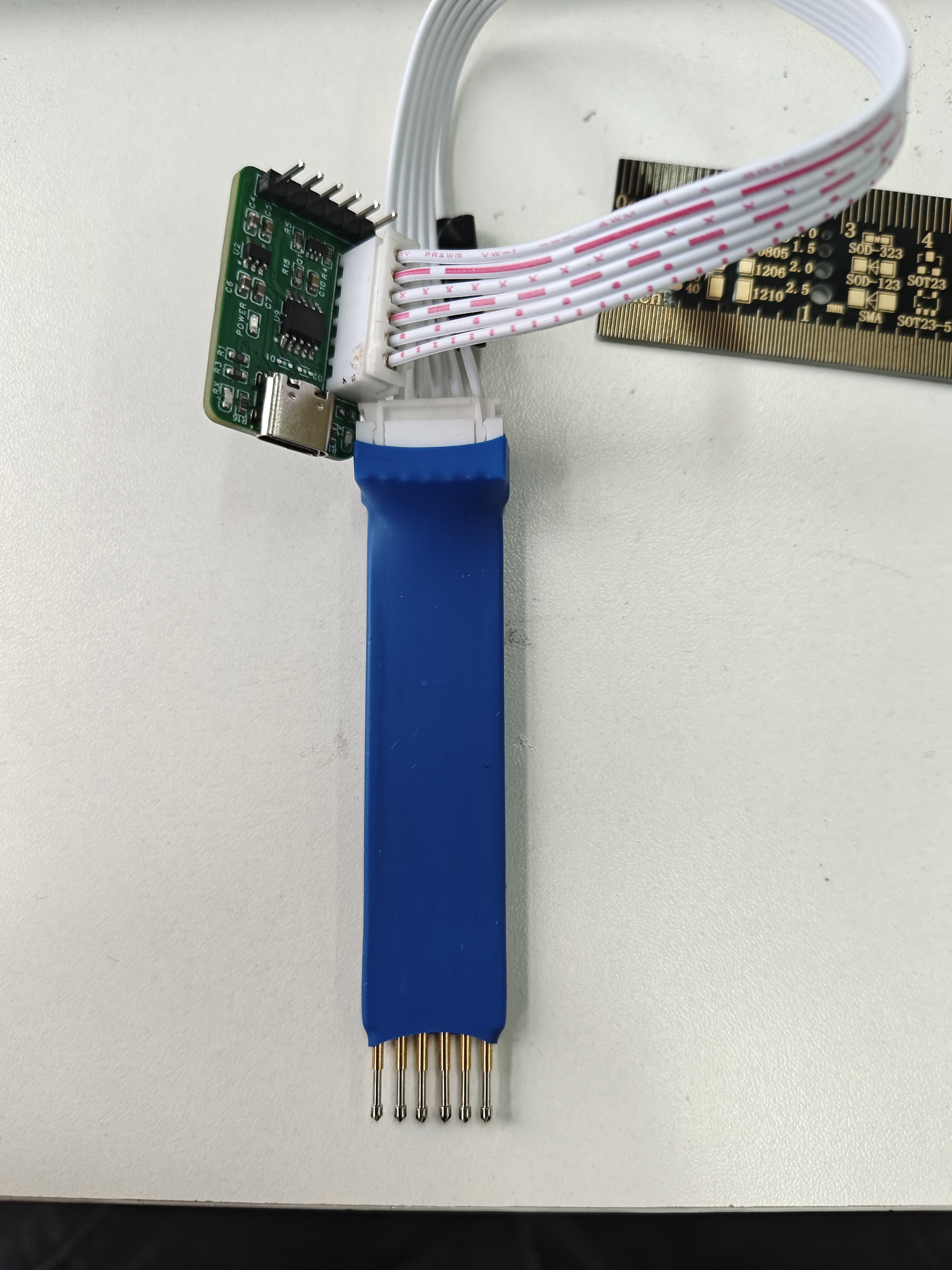
7. Slave Display Circuit Design:
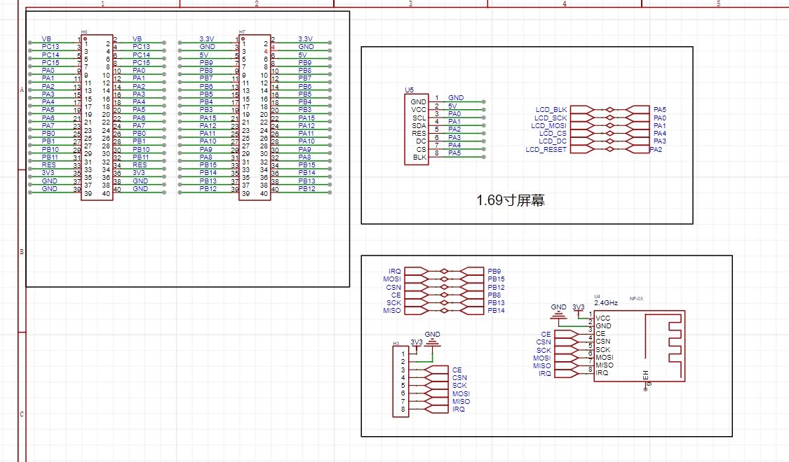
I used an STM32F103C8T6 for the slave device, employing a double-row female connector for easier debugging of other modules later.
This circuit mainly involves the design of the 2.4G module and the screen. Pin selection can be found in the datasheet or by referring to the datasheet for pin assignments.
IV. PCB Design:
The PCB design mainly involves several aspects: 1. Traces should not have right angles; 2. Power lines should be thicker. 3. Data transmission of some modules is easily interfered with. For example, there should be no metal underneath the 2.4G module, and other traces or components should be avoided under the antenna traces of the 4G module.
Master Unit: The layout is based on personal preference and the direction of the flying wires
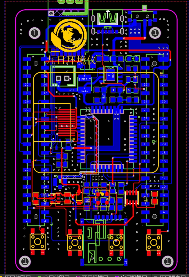
. Slave Unit: The screen components are drawn according to the manual to help you grasp the component dimensions and facilitate soldering. Bringing out the pins of the 2.4G module also facilitates debugging.

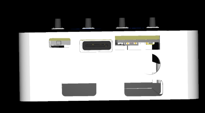
V. 3D Shell Design

VI. Program Explanation:
The code contains corresponding comments. If you have any questions, please leave a comment. The main point is to remember to change the device number, key, and name in the 4G module section to your own code. It has been tested and works without problems. If it doesn't work, it's mostly a hardware circuit issue.
VII. Functional Video Demonstration:
【Environmental Detector Production - Bilibili】 https://b23.tv/2csq6Hy
3DShell_Nine-Day Environmental Instrument.zip
BOM_Jiuri Environmental Monitoring Expansion Board_Jiuri Environmental Instrument PCB_2023-10-14.xlsx
32lcd slave.zip
PDF_Nine Days Environmental Meter.zip
Altium_Nine-Day Environmental Meter.zip
PADS_Nine-Day Environmental Meter.zip
BOM_Jiuri Environmental Instrument.xlsx
95585
Foolish Spectrum Light
A Fool's Spectrum Light
First, this is a rhythmic light; second, it can shock people!!!
The light board uses a WS2812B.

Regarding the capacitor issue, not every LED needs a capacitor. I didn't add any, and there were no problems. Hand soldering surface-mount components is quite tiring, especially with 64 LEDs, right? If there are no problems, it saves time. If problems arise, we can add capacitors later.
The control board uses the LCSC ESP32R8N8

pickup circuit, and the microphone circuit uses the MAX9814 solution.

Of course, for those who have difficulty soldering, a module interface can be used.

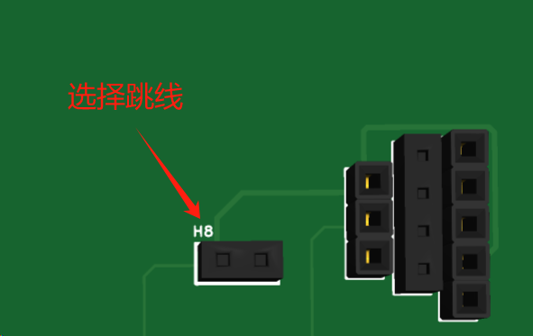
By selecting jumpers, you can decide whether to use a module or onboard soldering. The choice is yours. You can use the MX9814 (slightly expensive), the MAX4464 (mid-range price), or a microphone module based on the LM393 from Taobao (the cheapest). Looking at the wallet-shaped giant cauldron module, anyway, all the interfaces are reserved. When using the module
, pay attention to
the power supply and do not reverse it. Pay attention
to the power supply and do not reverse it. Pay attention to the power supply and do not reverse it .
I will say it three times because it is important
. Since this is a joke theme, pranks are indispensable .
The electric shock module
uses the universal chip NE555 to generate pulses, drive the transistor, and then drive the three-pin inductor (autotransformer). A high voltage is generated between the toggle switch and the back panel (don't worry, it's not fatal. You've all played with electric chewing gum when you were a kid, right? The principle is the same). Because this generates high voltage, I am worried about damaging other modules (mainly the development board. As a fan of women, I am very careful with the development board). Therefore, it is powered independently (6V or higher, below 12V is recommended).

H5 forms a circuit with the toggle switch and the battery.
H3 connects the toggle switch metal and the back panel.
H4 can be a through-hole three-pin inductor (because there is no through-hole three-pin inductor package in EDA).
The electric shock waveform measured by the oscilloscope after 10 times attenuation
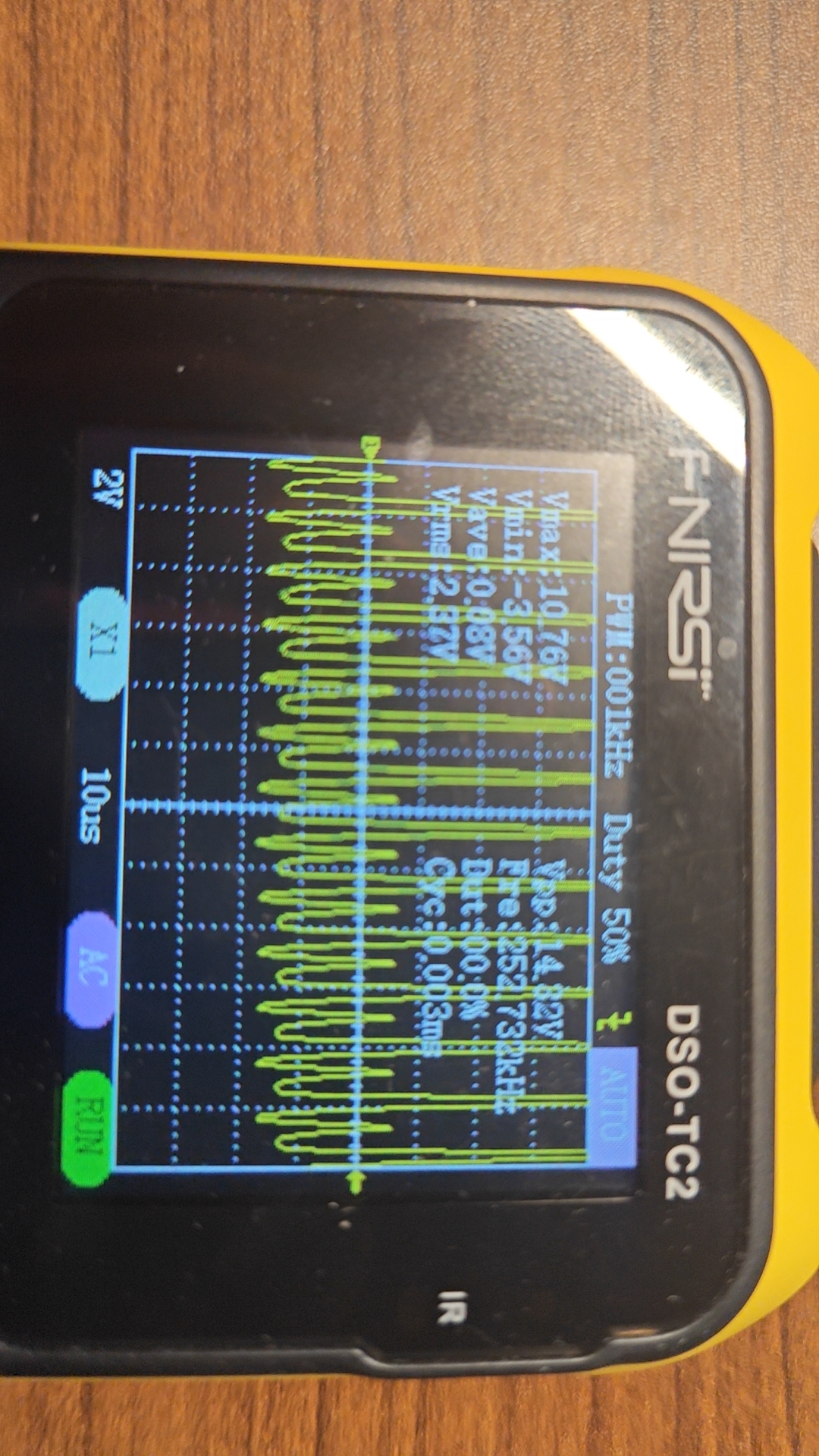
. Don't worry, the current is very small. This is a safe
code.
/*
This project is applied to the LC-ESP32R8N8 development board. */
Modifying the I/O ports can be applied to other ESP32 development boards
and Arduino development boards.
Learned from GitHub: https://github.com/Fudan-EGA/LEDSpectrum/tree/master
*/
#include // Install 1.6.1 for providing timing functionality in the program
#include // Install 3.5.0 for third-party Arduino libraries to control WS2812, LPD8806, and other LEDs
#include "arduinoFFT.h" // Install 1.6.2 for the open-source library of Fourier transform
arduinoFFT FFT = arduinoFFT(); // Create an FFT object
const uint16_t samples = 64; // Number of sampling points
const double samplingFrequency = 8000; // Sound sampling frequency
unsigned int sampling_period_us;
unsigned long microseconds;
double vReal[samples]; // FFT sampling input sample array
double vImag[samples]; // FFT operation output array
// FFT default parameter
#define SCL_INDEX 0x00
#define SCL_TIME 0x01
#define SCL_FREQUENCY 0x02
#define SCL_PLOT 0x03
// Interface and LED board
#define CHANNEL 4 // Audio input IO port number is 4
#define LED_PIN 1 // LED board input IO port selection
#define LED_NUM 64 // Number of LEDs
#define BRIGHTNESS 10 // Default backlight brightness
#define LED_TYPE WS2812 // LED type
#define COLOR_ORDER GRB // Color order
CRGB leds[LED_NUM]; // Define LED object
void setup() {
sampling_period_us = round(1000000 * (1.0 / samplingFrequency)); // Calculate sampling frequency
pinMode(CHANNEL, INPUT); // Initialize microphone interface to input mode, indicating reading microphone data
FastLED.addLeds(leds, LED_NUM); // Initialize LED strip
FastLED.setBrightness(BRIGHTNESS); // LED brightness setting, value range is 0-255
}
void loop() {
static uint32_t t = 0, dt = 5;
static uint8_t flag = 0;
/* Sampling */
microseconds = micros();
for (int i = 0; i < samples; i++) {
vReal[i] = analogRead(CHANNEL); // Read analog value, signal sampling
vImag[i] = 0;
while (micros() - microseconds < sampling_period_us) {
// empty loop
}
microseconds += sampling_period_us;
}
//Fourier Transform
FFT.Windowing(vReal, samples, FFT_WIN_TYP_HAMMING, FFT_FORWARD); /* Weigh data */
FFT.Compute(vReal, vImag, samples, FFT_FORWARD); /* Compute FFT */
FFT.ComplexToMagnitude(vReal, vImag, samples); /* Compute magnitudes */
fill_rainbow((leds), 64 /* Quantity */, 0 /* Starting color value */, 4 /* Incrementing value */); //Set rainbow gradient, first fill the entire area, then fill with black according to the value, indicating the light is off
for (int i = 0; i < 8; i++) { //Loop through the eight columns of LED
drawBar(i, (vImag[i * 3 + 2] + vImag[i * 3 + 3] + vImag[i * 3 + 4]) / 3 / 200, &flag); // Select 8 values after averaging the spectrum and pass the time flag to the drawing function
}
FastLED.show(); // Display the light bar
if ((millis() - t) > dt) { // Read the time and determine if the falling time has been reached
flag = 1; // If reached, mark it as 1
t = millis(); // Update the time
}
}
// Drawing function, draw the length according to the frequency
void drawBar(int idx, int16_t value, uint8_t *flag)
{
static int16_t volume[8]; // Save the falling data
consttrain(value, 0, 8); // Amplitude is limited to the range of 0-8
if (volume[idx] < value) // If the collected data is larger than before, update to achieve the upward effect
volume[idx] = value;
if (idx % 2) { // Remainder 2 operation to determine if the sequence number is odd
for (int i = 0; i < 8 - volume[idx]; i++) leds[idx * 8 + i] = CRGB::Black;
} else {
for (int i = volume[idx]; i < 8; i++) leds[idx * 8 + i] = CRGB::Black;
}
if (*flag) {
volume[idx] -= 1; // Decrease by 1 when the time is reached, indicating a fall
if (idx == 7) *flag = 0; // Clear the flag after all columns 0-7 have been updated
}
}
Be careful when playing pranks, including but not limited to getting beaten up.
Be careful when playing pranks, including but not limited to getting beaten up.
Be careful when playing pranks, including but not limited to getting beaten up.
cb6e67064a942a8fee80f3a9beb91ad8.mp4
fcd4488f181f5a38f7abae5fb556710a.mp4
PDF_Fool's Spectrum Light.zip
Altium_Entertainment Spectrum Light.zip
PADS_Entertainment Spectrum Light.zip
BOM_YuleSpectrumLight.xlsx
95586
electronic


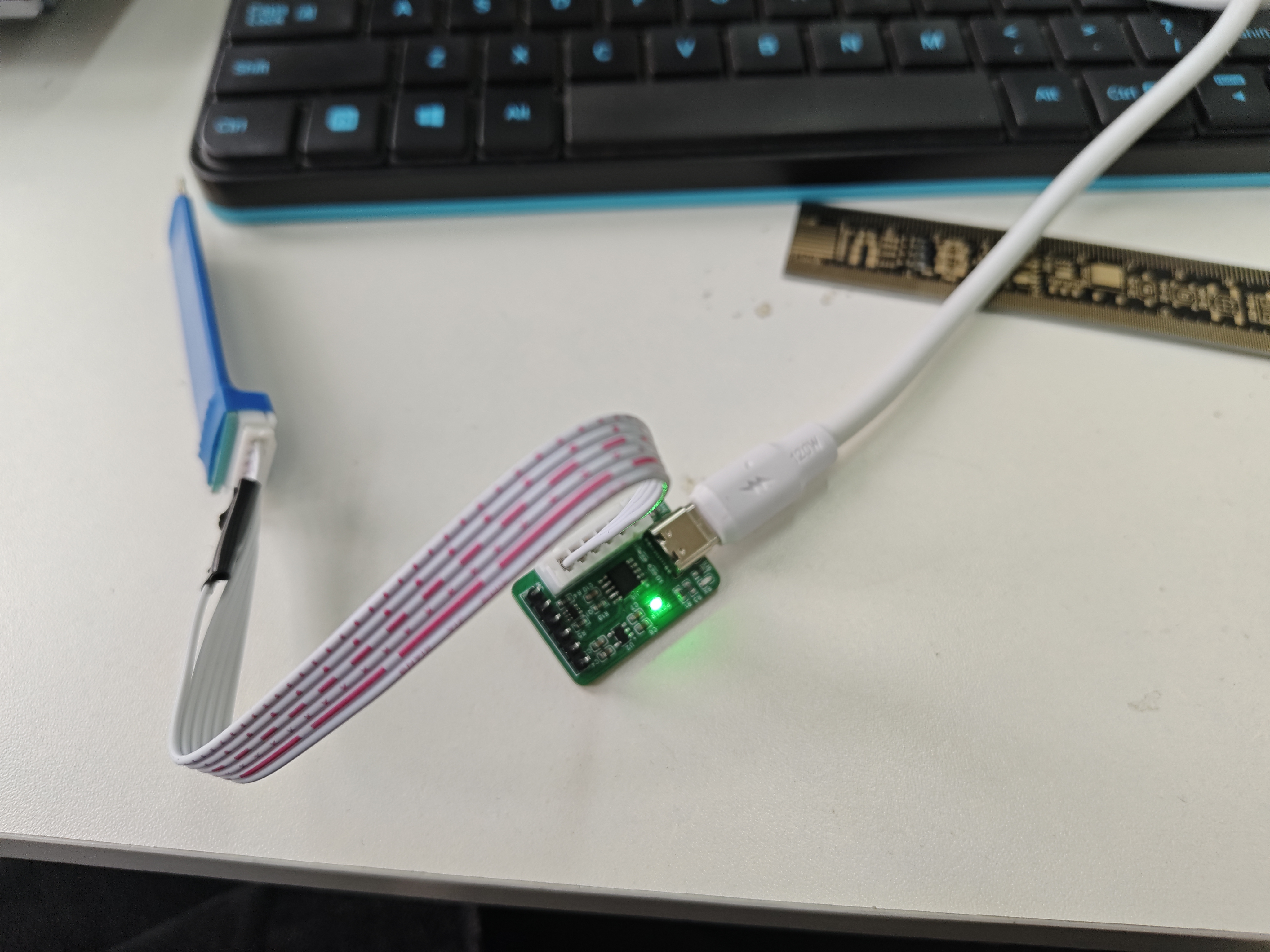

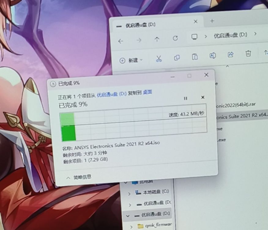 A 2.0 hub reaching 43.2MB/s is quite fast, with virtually no heat generation. For the four-layer board, just follow the stacking order in the documentation.
 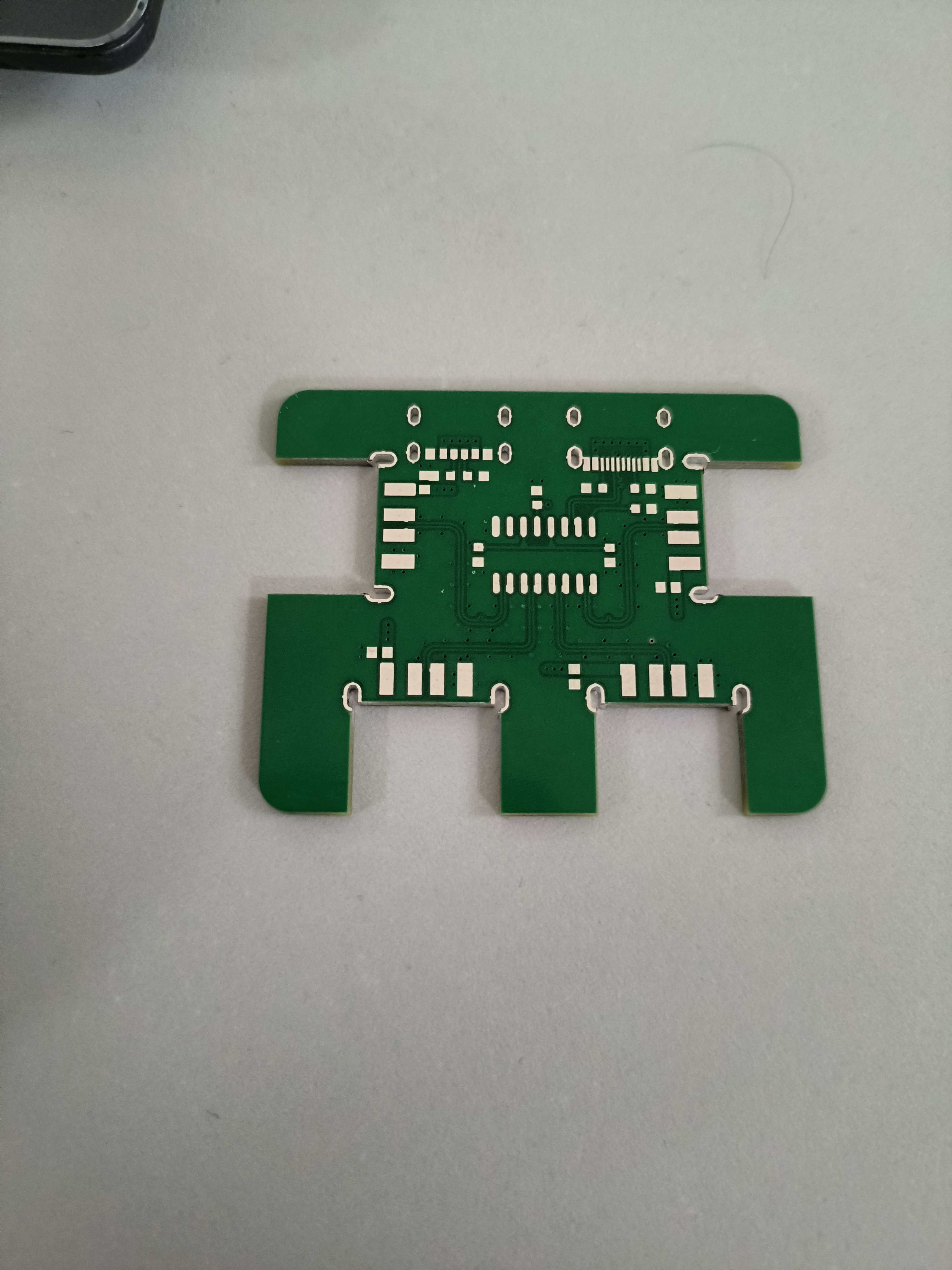 It's possible that after receiving the board, you might find the speed doesn't reach 43MB/s. This could be due to the USB drive's inherent speed limitations or issues with the 2.0 USB cable routing in the computer case.
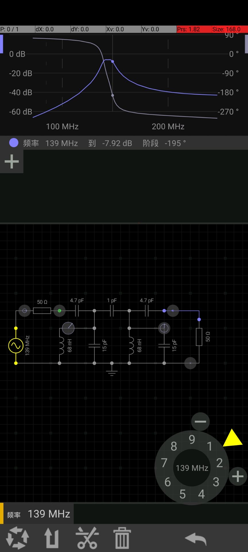
 Simulation results are:
 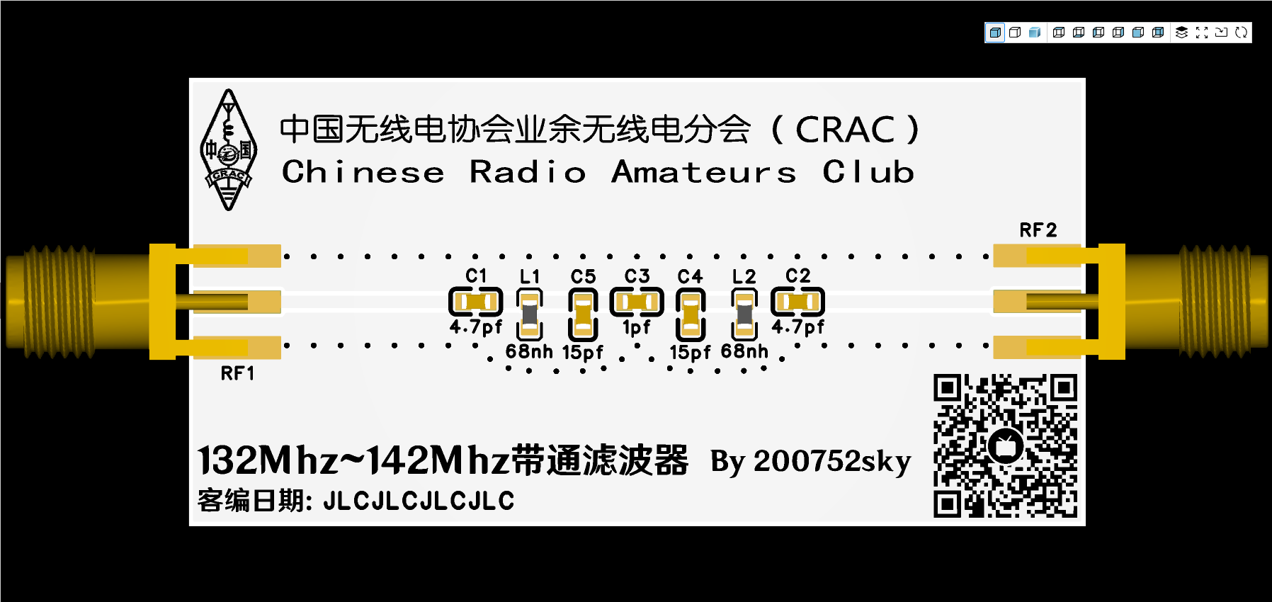 ★ Physical image:
  ★ Production process:
 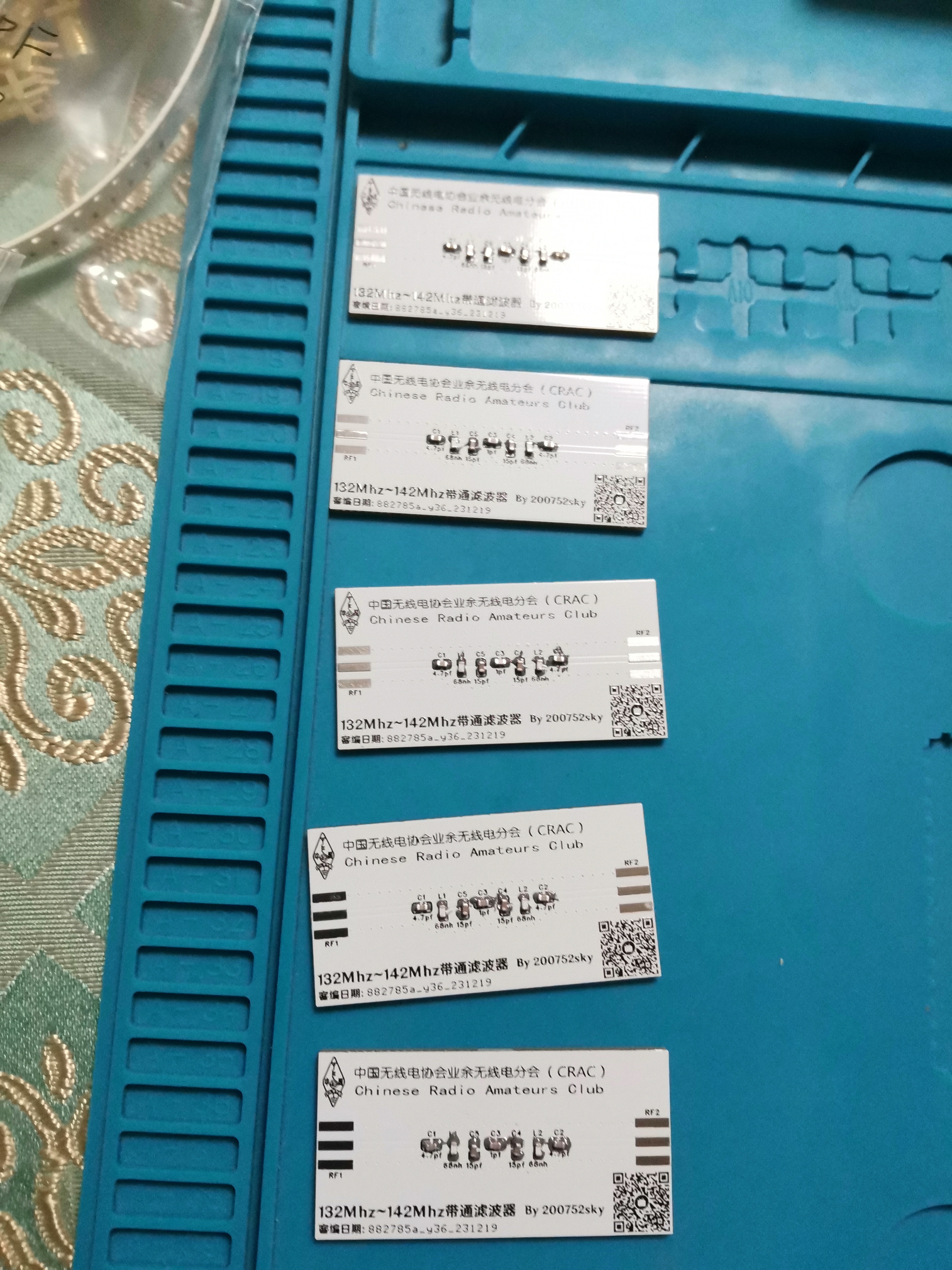 3. Manual reflow soldering
 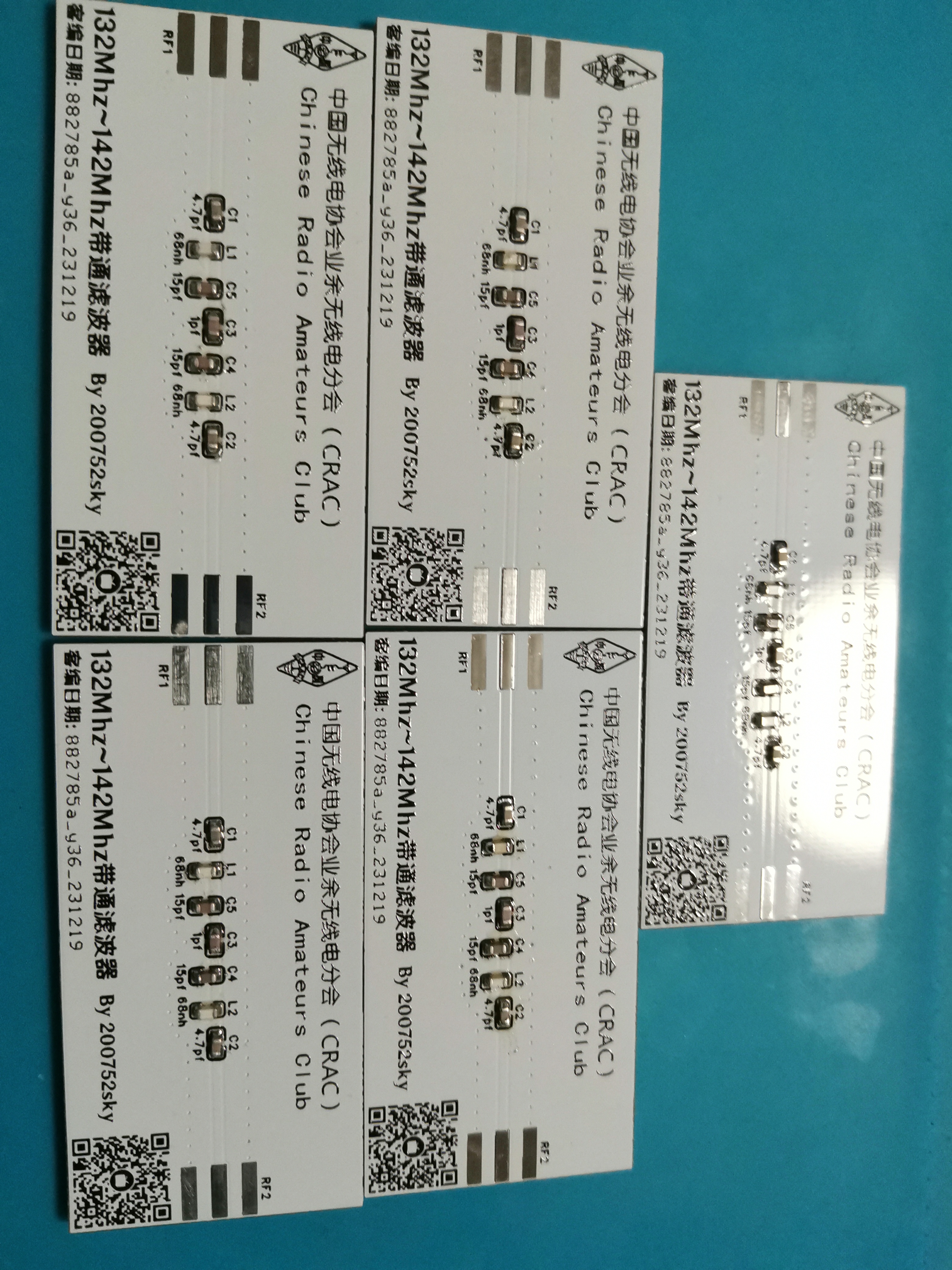 4. SMA connector soldering 5. Board cleaning solution
 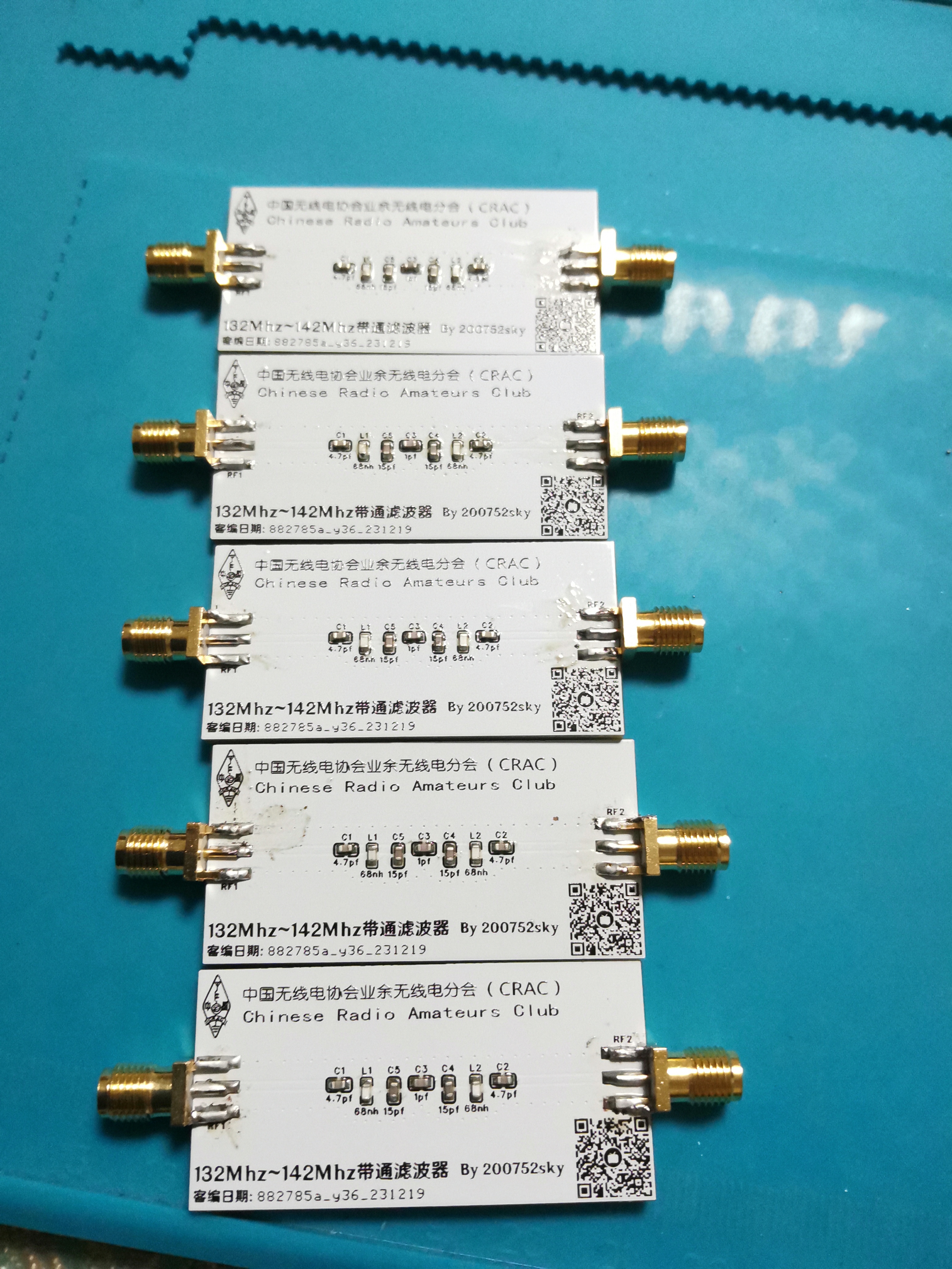 , clean and smell good (completed)
  When making the board, remember to check the box for adding custom code at the specified location, board thickness 1.6mm, the rest are default, color is arbitrary.
  ————————————————————————————————————
 , and an MG995 servo motor (an SG90 can also be used, depending on the lock's resistance). The required environment includes a
  (Powered from the dormitory Wi-Fi's USB port, or powered by a charger (a cheap and stable 5V 1A charger will suffice)).
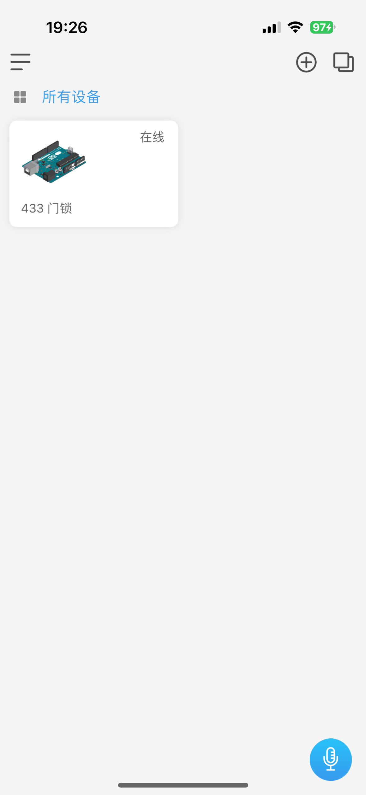


 京公网安备 11010802033920号

 ST62P08LT1/OTP


