STM32F103Rx core interface board.
I've copied many core boards from various developers, and I wanted to design my own. My work recently required testing many sensors, so I designed this interface board based on my needs. Please feel free to point out any errors.
USB/programming section:
The onboard CH334R acts as a USB hub. After connecting the Type-C interface, the connection goes through the CH334R to DAPLink, then to the STM32USB peripheral, and finally to the CH32V203 as a DAPLink. DAPLink can be used for programming and debugging tools and as a CDC virtual serial port. This DAPLink solution is used, thanks to the developer who made it open source: https://oshwhub.com/legend-tech/dap-link-ch32v203f6p6
The CH334R datasheet indicates an external 12MHz crystal oscillator, which I've confirmed is necessary (don't ask, it's a long story). However, the oscillation capacitor is optional; I've only included it here for future reference. It doesn't actually need to be soldered.
Additionally, I removed the CC1 and CC2 pins from my TYPEC interface. In actual testing, connecting certain CC lines resulted in no power supply. If possible, please modify this; I will fix it in the next version (hopefully there will be a next version).
MCU Section:
External Interfaces:
Serial Port 1: External - Dedicated Interface
Serial Port 2: 485 External - Dedicated Interface. 485 has an automatic switching circuit, but manual control is also possible. For manual control, please solder Q3 blank
. Serial Port 3: 232 External/TTL Serial Port External/IIC2 External - Dedicated Interface. 232 requires changing the 0R resistor
. Serial Port 4: 232 External - Dedicated Interface
Serial Port 5: Connects to DAPLink's CDC virtual serial port, can connect to a computer.
CAN/USB: Selected via 0R resistor; USB connects to a HUB chip.
SPI1: External - Pin header (compatible with NRF24L01 interface).
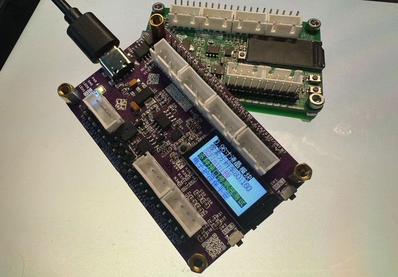
SPI2: 0.96-inch color screen;
IIC1: BMI160 gyroscope;
IIC2: See serial port 3;
Software IIC: Connected to EEPROM;
Other onboard resources:
Buzzer,
User LEDs*2
, User buttons*2
, MCU reset button*1
, MCU external 8M crystal oscillator and 32.768K crystal oscillator
;
Additional information:
I made a base plate for the board, and the 3D printing effect is acceptable. The file is attached.
I plan to draw an acrylic top plate for this board later, but I've been busy lately and haven't had time to make a prototype. The file is in the project.
The board program is still being written: Progress:
The general framework of the program is now complete. The display part is finished (proving the screen works).
The serial port part is finished (proving the serial port and RS-232 work).
The gyroscope part is half finished (data transmission is working, but data settlement is not yet written) (proving that IIC at least works).
The buzzer sounds, but this part of the program has not been written yet.
The button part is finished (proving the buttons work). The RS
-485 part is not finished yet, but it should be usable.
The CAN/USBZ part wasn't written well, and I'm not sure if it will work (the CAN circuit has been verified).
Finally:
This project went through two versions, as you can see from the green and purple covers. Version V1 had some issues, while version V2 should be able to be directly boarded. I estimate that if I have time, I'll probably revise it to a third version, readjusting the MCU interface wiring sequence and separating USB and CAN. If possible, I'd also like to change the board layout, replacing the current through-hole XH2.54 with a side-mounted connector, making the acrylic a single piece. However, I'm so busy with work; it'll probably be a long time coming.


 京公网安备 11010802033920号

 1-A-07-048.0-08-G-2


