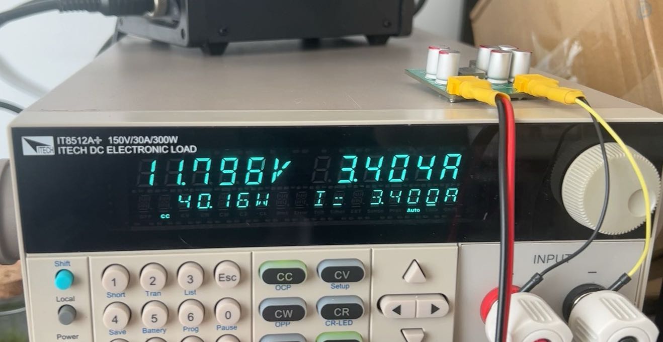
This project was designed based on Ti's official manual. Because the application scenario had some, but not many, EMI requirements were considered, so a simpler layout was adopted, with increased input and output capacitors. In actual testing, it worked very well, with excellent load regulation. Currently, the ripple and noise are only around 8mV at 2A output. The image below shows the current measured by the oscilloscope when the output reaches 3.4A (the 5430 is rated at 3A).
After a long period of load testing (8 hours at 1A, 8 hours at 2A, 8 hours at 3A, 4 hours at 3.5A), the inductor gets slightly warm at 3A and above, but the overall board heat dissipation is still good. At a room temperature of 20 degrees Celsius, the board temperature reached 49 degrees Celsius after the entire test.
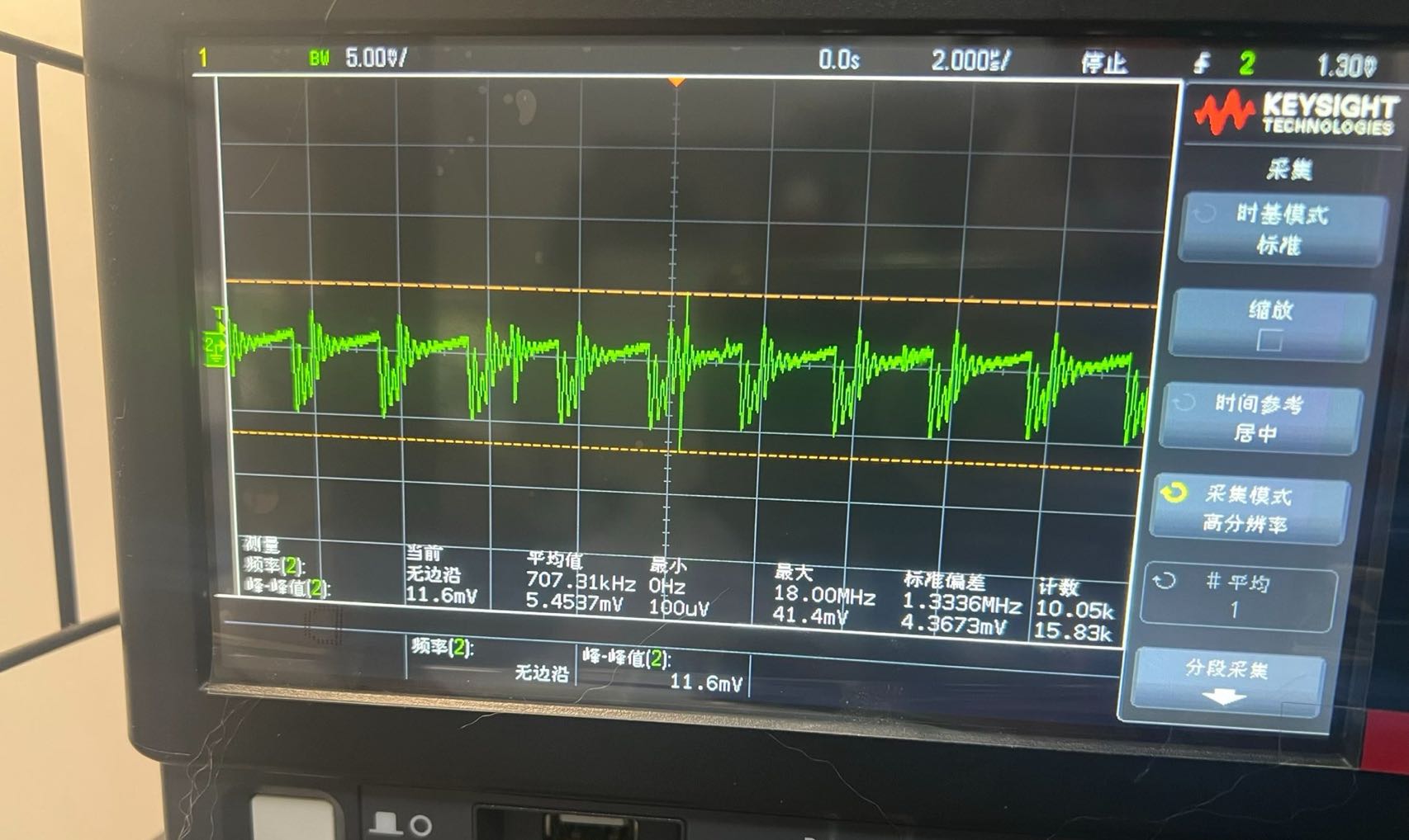
The image below shows operation above the rated current.
BOM_TPS5430 Adjustable Step-Down Power Supply with Test Graphs.xlsx
95758
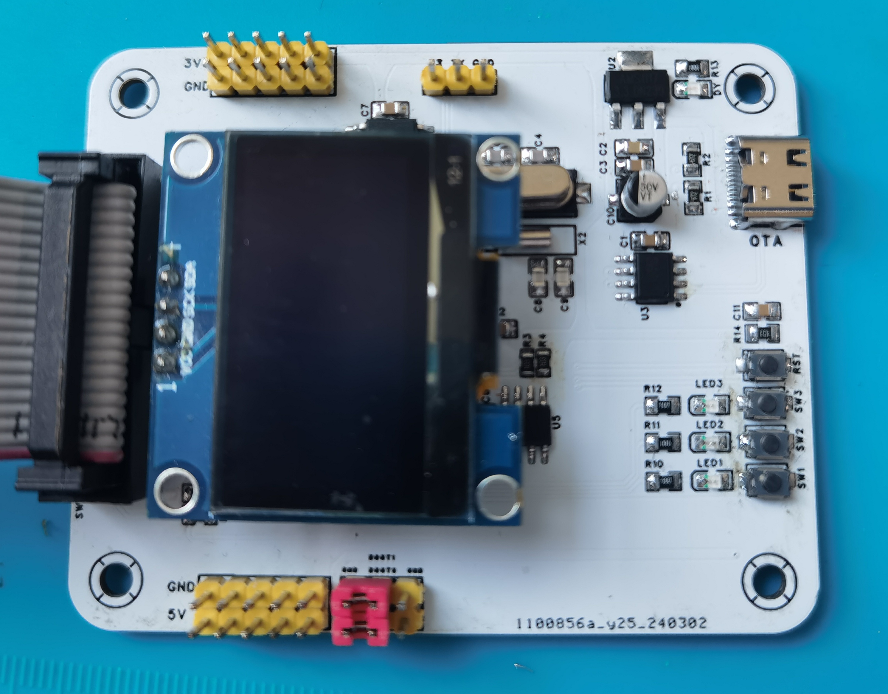
MP2236+CH224K, 15V to 5V power supply module
15V to 5V power supply module
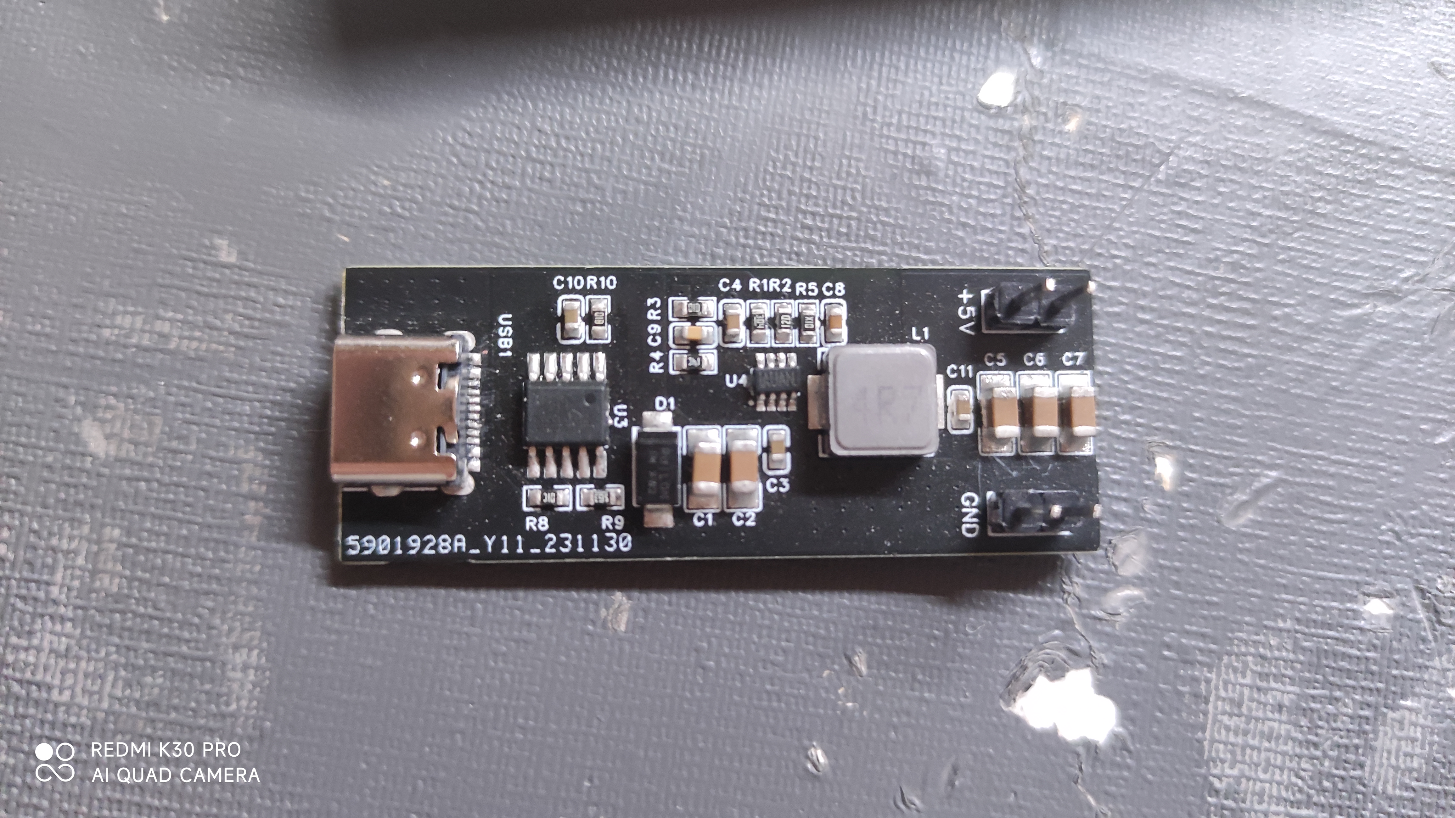
Figure 1 shows the original design,
originally intended for a course project to create a 5V power supply with lower ripple.
The input PD decoy chip uses a CH224K, a single-resistor configuration, with a decoy voltage of 15V. This can be modified, but care must be taken not to exceed the withstand voltage of the MP2236.
The MP2236 can be replaced with MP2225, MP2315, etc.
The original design differs slightly from the current version, mainly in the wiring of the Type-C interface.
A simple test was conducted using a cement resistor to check the ripple under open-circuit, 1A, and 5A output conditions.
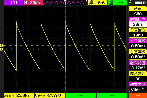
Figure 2 shows the open-circuit output .
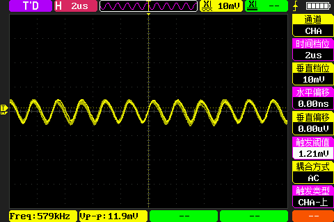
Figure 3 shows the 1A output.
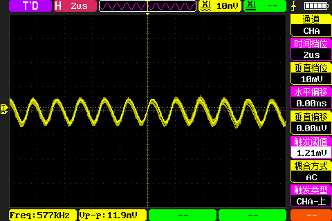
Figure 4 shows the 5A output.
PDF_MP2236+CH224K, 15V to 5V power supply module.zip
Altium_MP2236+CH224K, 15V to 5V power supply module.zip
PADS_MP2236+CH224K, 15V to 5V power supply module.zip
BOM_MP2236+CH224K, 15V to 5V power supply module.xlsx
95759
Learning and development board based on STM32F103C8T6
The development board designed using the STM32F103C8T6 includes a variety of functions, making it easy for learners to use.
The development board designed using the STM32F103C8T6 includes
a W25X16 FLASH chip with an SPI interface,
a 24C02 memory chip with an I2C interface, a
0.96-inch I2C LCD screen,
a CH430N serial port, download
buttons, and LEDs.
PDF_Learning and Development Board Based on STM32F103C8T6 Design.zip
Altium_Learning Development Board Based on STM32F103C8T6 Design.zip
PADS_Learning Development Board Based on STM32F103C8T6.zip
BOM_Learning Development Board Based on STM32F103C8T6 Design.xlsx
95761
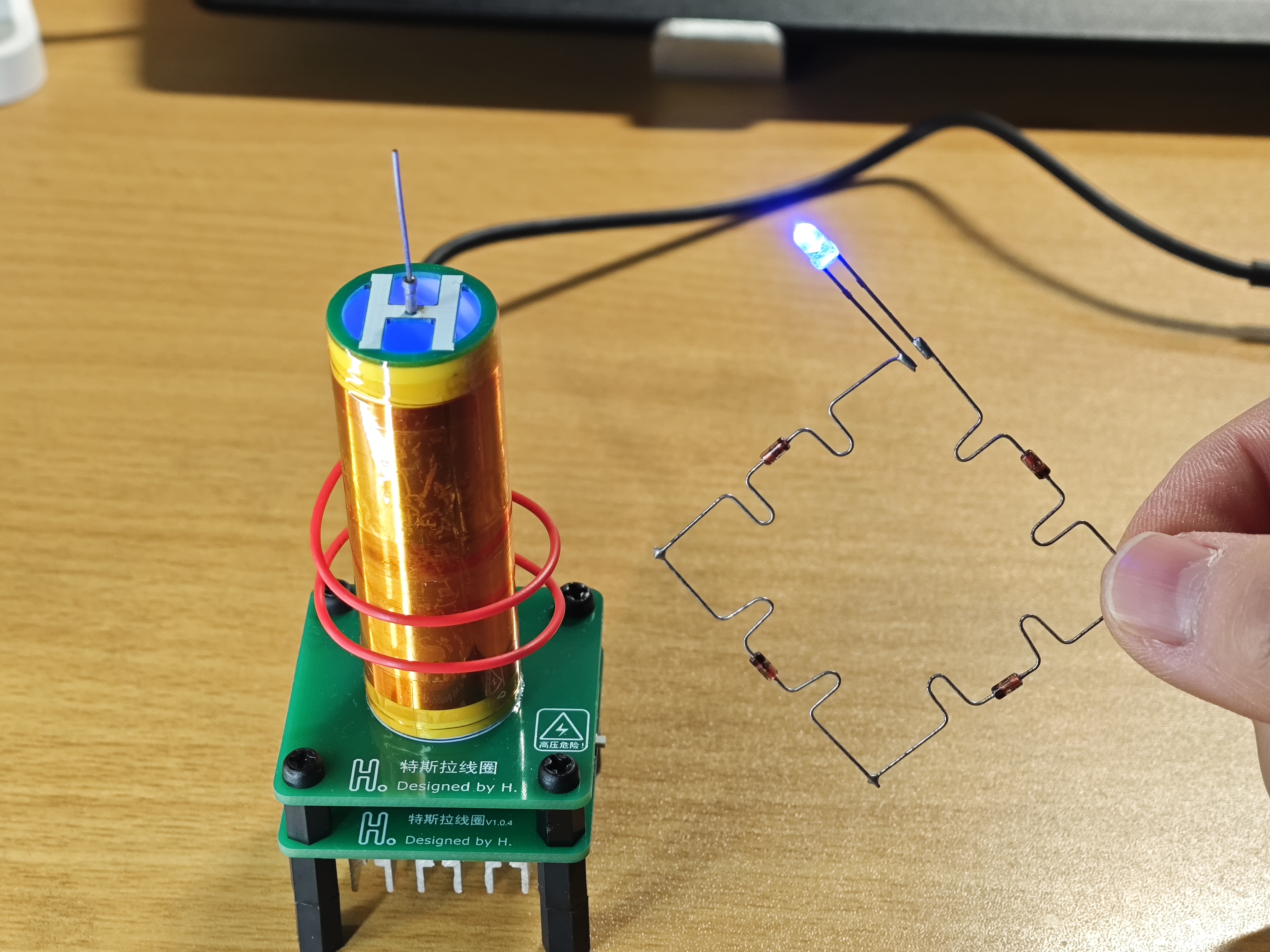
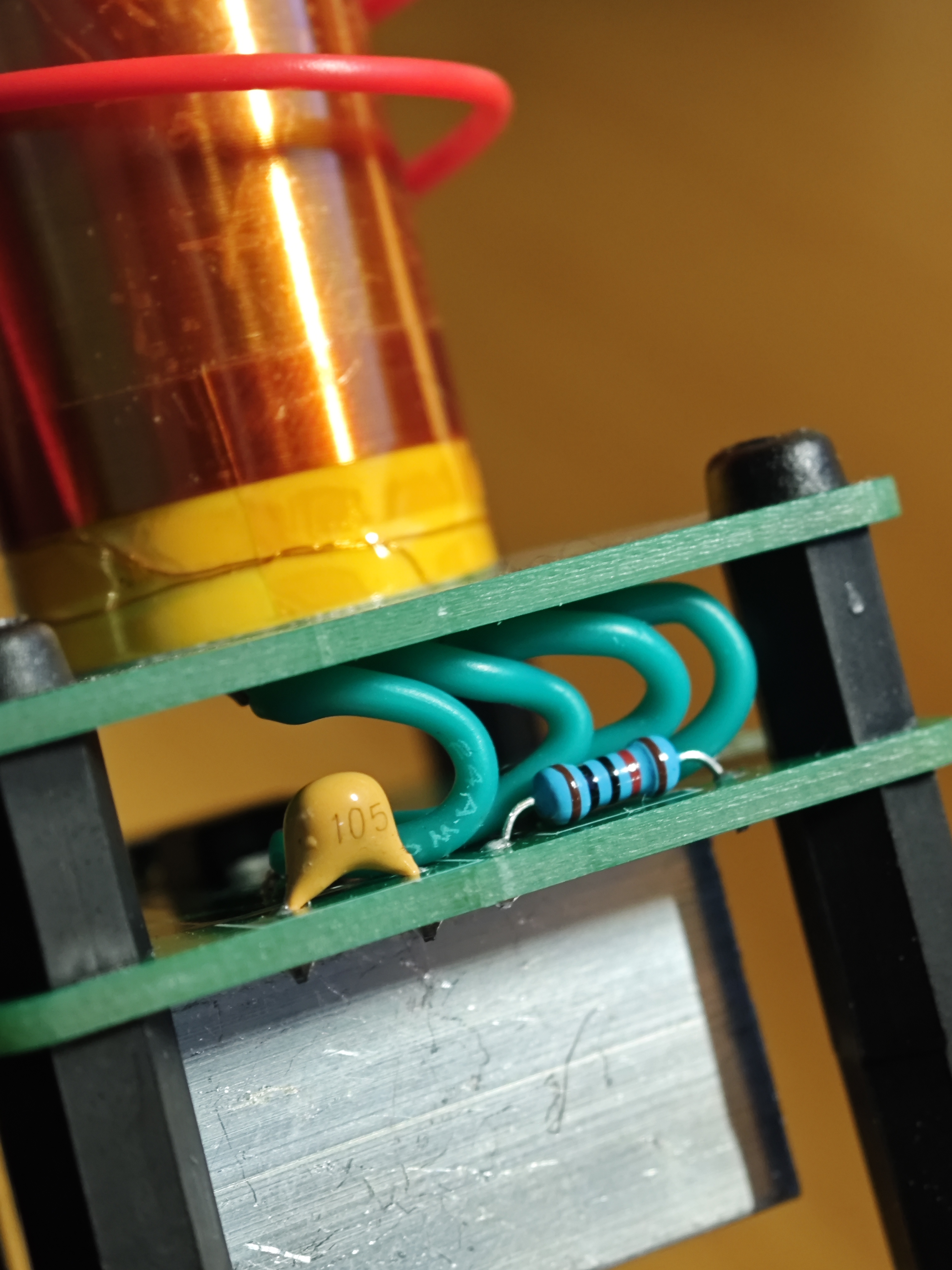
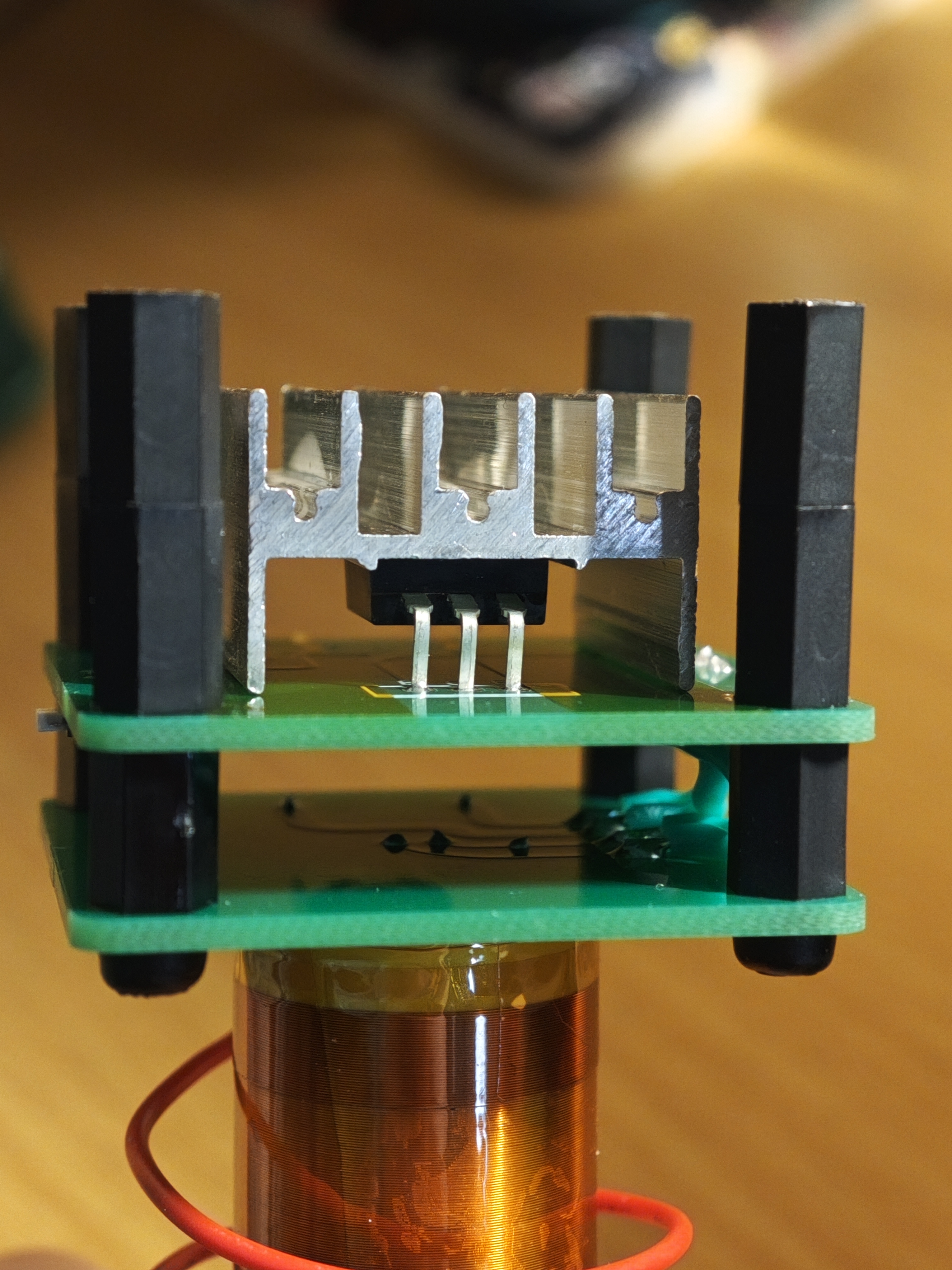
Tesla coil
A small Tesla coil capable of arcing and powered up to 24V.
Bilibili video link: Click to play.
Please be careful! It's not your safety (harmless to the human body, at most you'll get a burn or a slight arc burn), it's the safety of your electronic devices. Tesla coils are highly damaging to precision electronic devices; getting too close can cause malfunctions or even burnout. Please keep Tesla coils away from electronic devices!!!
Actual product image:

Functions:
1. Type-C power supply, with CC resistor, supports CC cable.
2. Includes an independent switch.
3. Wireless lighting (5V power supply, no heat generation, can run for extended periods).

Uses four 1N4148 high-frequency detector diodes in series; 5V can wirelessly power approximately 15cm, with extremely high efficiency. Adding more series can increase the distance!
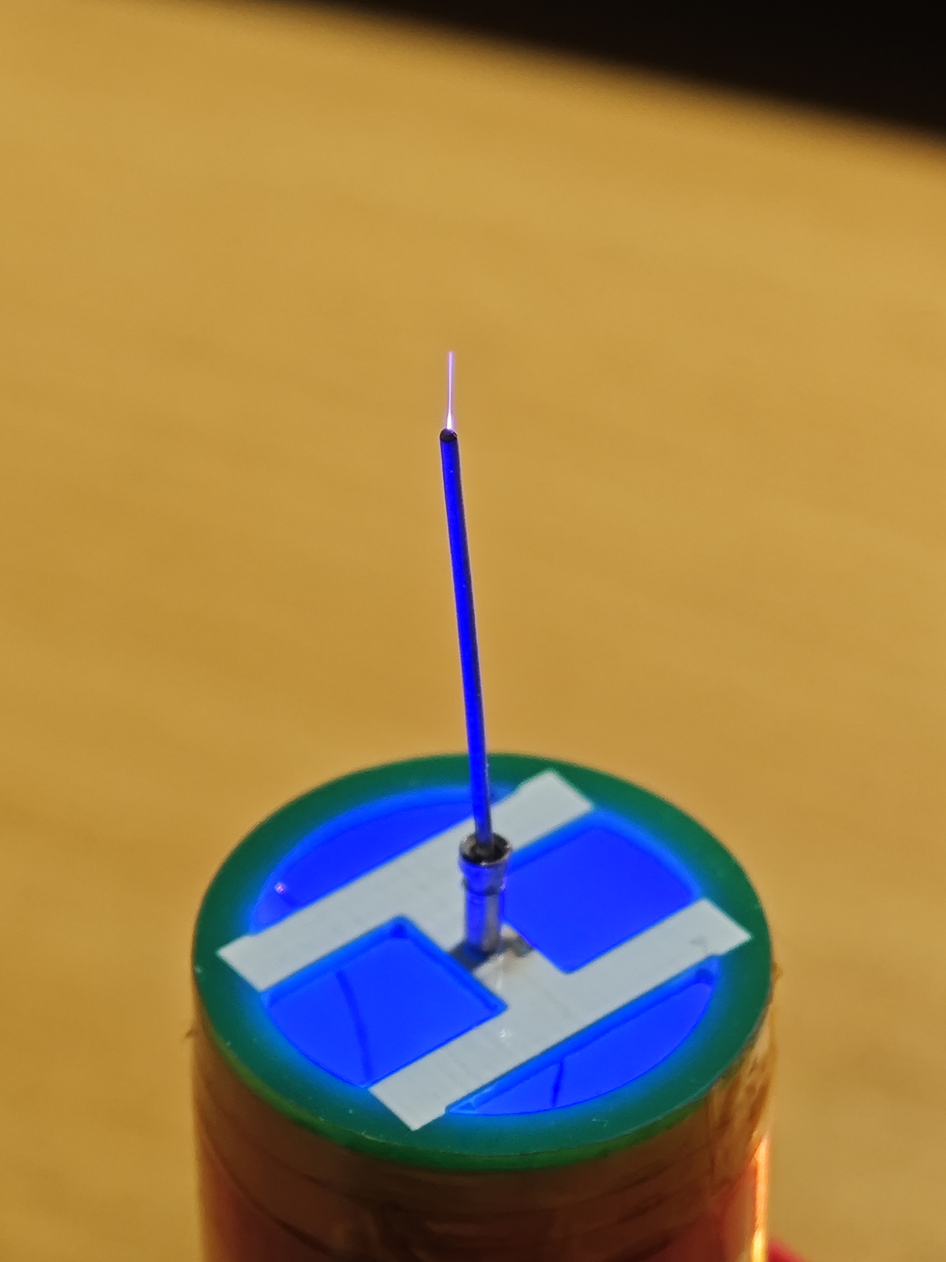
4. Arc spraying (the image shows 9V power supply; 20V power supply is better, but it gets very hot and requires water cooling, and cannot run for extended periods).
Working principle: Tesla coils are over a hundred years old, and many excellent science popularizers have created videos about their principles. To improve the completeness of this open-source project, I will briefly describe its working principle as I understand it: When powered on, the base of the transistor is pulled high by R1, turning the transistor on. The primary coil is energized, generating a magnetic field. The secondary coil generates an induced electromotive force. There is an equivalent capacitance between the secondary coil and the air, forming an LC resonant circuit. Since one end of the secondary coil is connected to the base of the transistor, the oscillation signal is fed back to the transistor. As the transistor turns on and off with the signal, the primary coil is also energized and de-energized. The magnetic field generated by the primary coil replenishes energy to the LC resonant circuit of the secondary coil, allowing the circuit to continue working. Simply put, it is a positive feedback circuit.
Replication Notes:
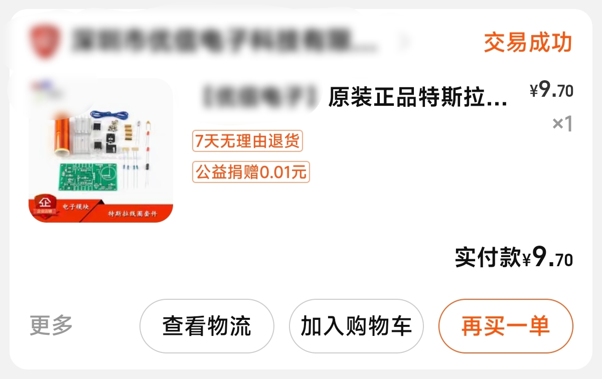
1. This open-source project uses parts from a kit purchased from Taobao. The following need to be purchased separately: Q2 MOSFET (model NCE6050KA); toggle switch 12C02; 0603, 5.1k, 1k, 10k.
2. Do not operate for extended periods with a 20V or higher power supply. Always monitor the heatsink temperature, even when submerged in water, as the water will boil. Additionally, pay attention to the water level and avoid touching any live areas other than the heatsink.
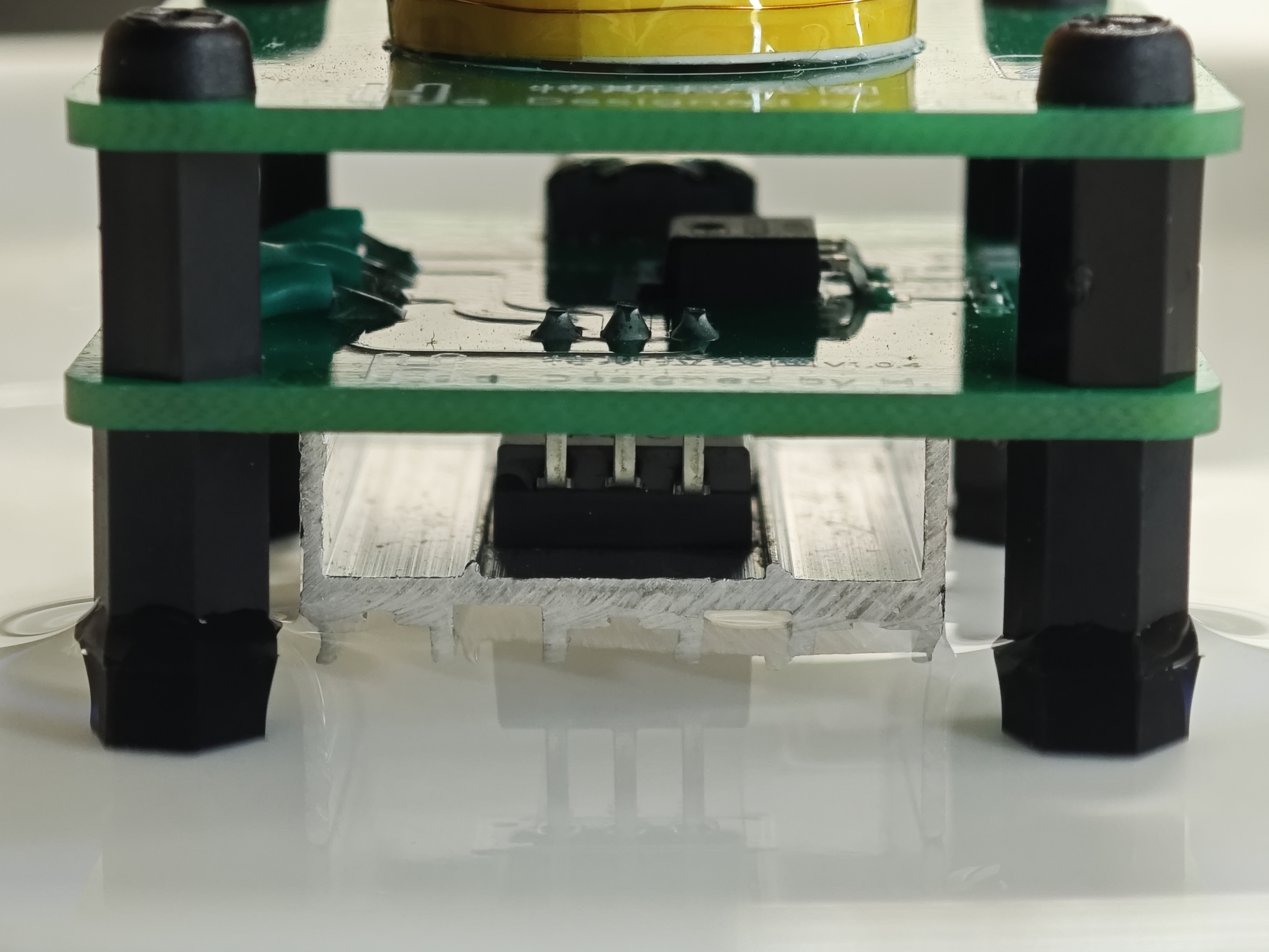
3. The product consists of two boards, stacked together, connected by wires. The wires should not be too long, as this will affect the resonant frequency and reduce efficiency.
4. Do not install the transistors according to the silkscreen markings; bend them at a 90-degree angle so the heatsink fits snugly against the base plate. Pay attention to electrical protection; apply high-temperature tape to the contact points with the base plate.
5. The board size and screw holes are not arbitrary; they are designed to fit a standard 4*4 cm cooling fan, but air cooling is not as effective as water cooling.

6. Remember to use nylon pillars; do not use copper pillars or other metal pillars, as these will affect the resonant frequency.
7. The primary coil has two turns.
8. The secondary coil has a diameter of 2 cm and 300 turns, although I haven't counted them; it's listed in the kit.
9. The secondary coil needs to be secured with glue; I recommend using a flexible glue like B7000.
10. The secondary top cover is for aesthetics; it's optional for normal operation.
11. There are three types of nylon pillars: M3*8mm through pillars, used for interlayer spacing; M3*10mm pillars with a nut on one end and a screw on the other, the screw being 5mm long, used for four-corner supports; and M3 screws, 5mm long.
Random thoughts:
This piece really suits my aesthetic; it's small and exquisite, and looks especially good on my desk. I love it!!!
Thank you for watching! Best wishes for successful replication!
PDF_Tesla Coil.zip
Altium_Tesla coil.zip
PADS_Tesla Coil.zip
95762
The night light that my roommate is crazy about
This product is a night light made with a WS2812 as the main body and a 3D-printed shell. My roommate happily placed the night light you gave him by his bed.
However, the next morning at 7:30, he was still asleep when he was startled awake by a rapid beeping sound, and a bright white light forced him to get out of bed. My roommate is absolutely obsessed with this night light.
LCSC's "Electronic Fun" Call for Submissions! A nightlight that will drive your roommates crazy!
The 3D-printed shell is fantastic, the touch switch is incredibly practical, and the prank mode is terrifyingly scary (but use with caution, your roommates will really go crazy!).
It uses the ESP8266 as the main controller and the WS2812 as the core. The 3D-printed shell allows for custom panel printing. Remote control software is included, making it easy for beginners to replicate! For
the full demo video, please visit Bilibili: 【My First DIY Nightlight in College, and It's Driven My Roommates Crazy?! - Bilibili】 https://b23.tv/a1O1eYo
PCB Board Fabrication:
Design the circuit diagram and PCB layout for the nightlight. (This part references schematics from some open-source projects.)
Use PCB design software, such as Altium Designer or Eagle, to create the PCB design file.
Send the Gerber version of the design file to LCSC for production. You can choose to produce locally or order online.
3D Printing:
Design the nightlight's shell model using CAD software. Considering the lamp's shape and size,
prepare a 3D printer and suitable materials such as PLA or ABS.
Convert the designed shell model to STL file format.
Set the printing parameters on the 3D printer and start printing the shell model.
Wait for printing to complete and remove the printed shell model.
Assembly process:
Fix the PCB board inside the 3D printed shell, ensuring correct circuit connections.
Install necessary components such as LED lights and batteries onto the PCB board.
Close the shell, ensuring all parts are securely fixed together.
Perform circuit and functional tests to ensure the night light works properly.
If everything is normal, complete the assembly process, and the night light is ready for use.
PS: Due to university students still needing to rush assignments and the activity deadline approaching, the ESP platform part will be packaged and uploaded later.
base.zip
Example image 1.jpg
Example image 2.jpg
Example image 3.jpg
Gerber_PCB1_2024-03-02.zip
studio_video_1710158475763.mp4
PDF_The Night Light My Roommate Is Crazy About.zip
Altium - The nightlight my roommates are crazy about.zip
PADS_The Night Light My Roommates Are Crazy About.zip
BOM_The nightlight my roommates are going crazy for.xlsx
95765
electronic


 京公网安备 11010802033920号

 SHX1
SHX1


