An electronic load based on the STC8H1K17T microcontroller is used. Due to limited capabilities and microcontroller resources, it is only a simple, usable device with basic functionality.
Four buttons control the output current: +1A, -1A, +0.1A, and -0.1A. The load stops when the parameter is 0. (
Video: Electronic Load Based on STC8H1K17T - Bilibili)
The ceiling light I bought on Xianyu (a second-hand marketplace) has an ESP32 chip that can be connected to the Mi Home app for Wi-Fi control. This project is a verification board for this module.
The goal
was to remotely control a switch via the Mi Home app. Smart switches with Wi-Fi on Taobao typically cost around 30-40 yuan, but pre-built Wi-Fi modules would be much cheaper. With this in mind, I found a disassembled ESP32 module on Xianyu (a second-hand marketplace) that perfectly met my needs.
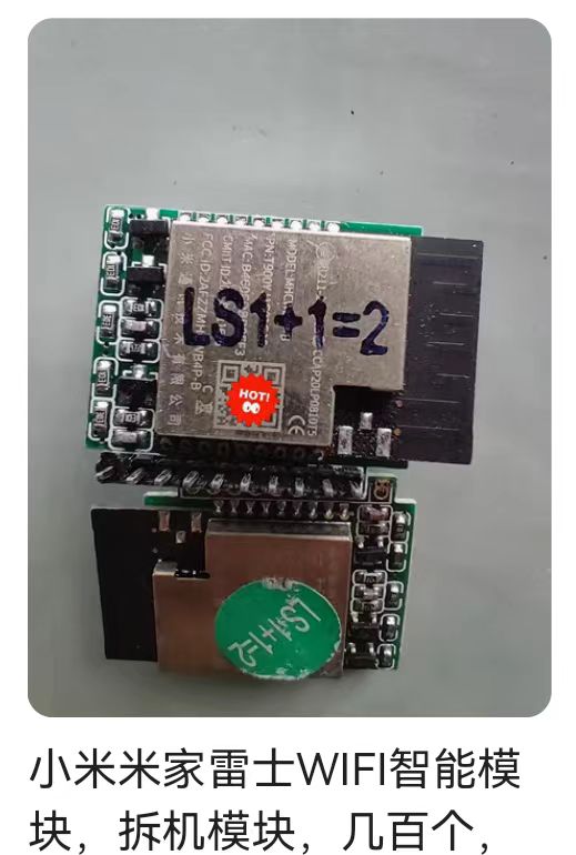
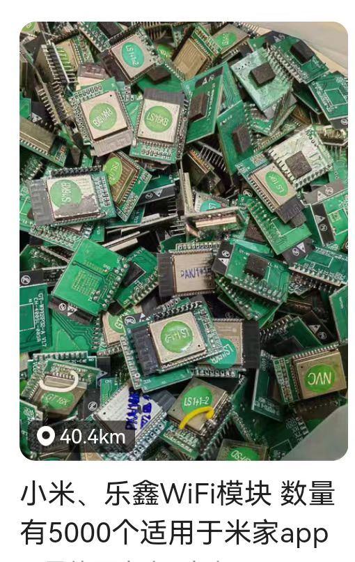
After testing, I found that the NVC Smart LED Ceiling Light worked best, generally costing between 3 and 6 yuan.
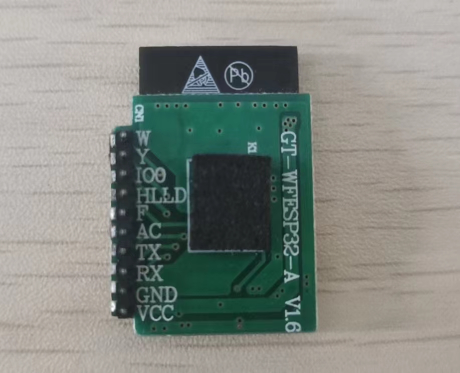
The module is 3.3V powered. The Y and W pins are two PWM outputs, corresponding to yellow and white light.
The AC pin is the button pin; a low level indicates it's pressed. The button function depends on the module itself, but it's generally for turning the light on and off. Pressing it 8 times and then powering off resets the module. The
functions of the other pins are currently unknown; if anyone knows how to use them, please leave a comment.
After powering on the module, you can find a device named "NVC Smart LED Ceiling Light" in the Mi Home app. Pair it and enter the Wi-Fi password.
This project is a verification board for the module. The module has been prototyped and verified. It has two PWM controls and two USB power outputs, which can be connected to LED lights or small fans, and includes an AC function button.

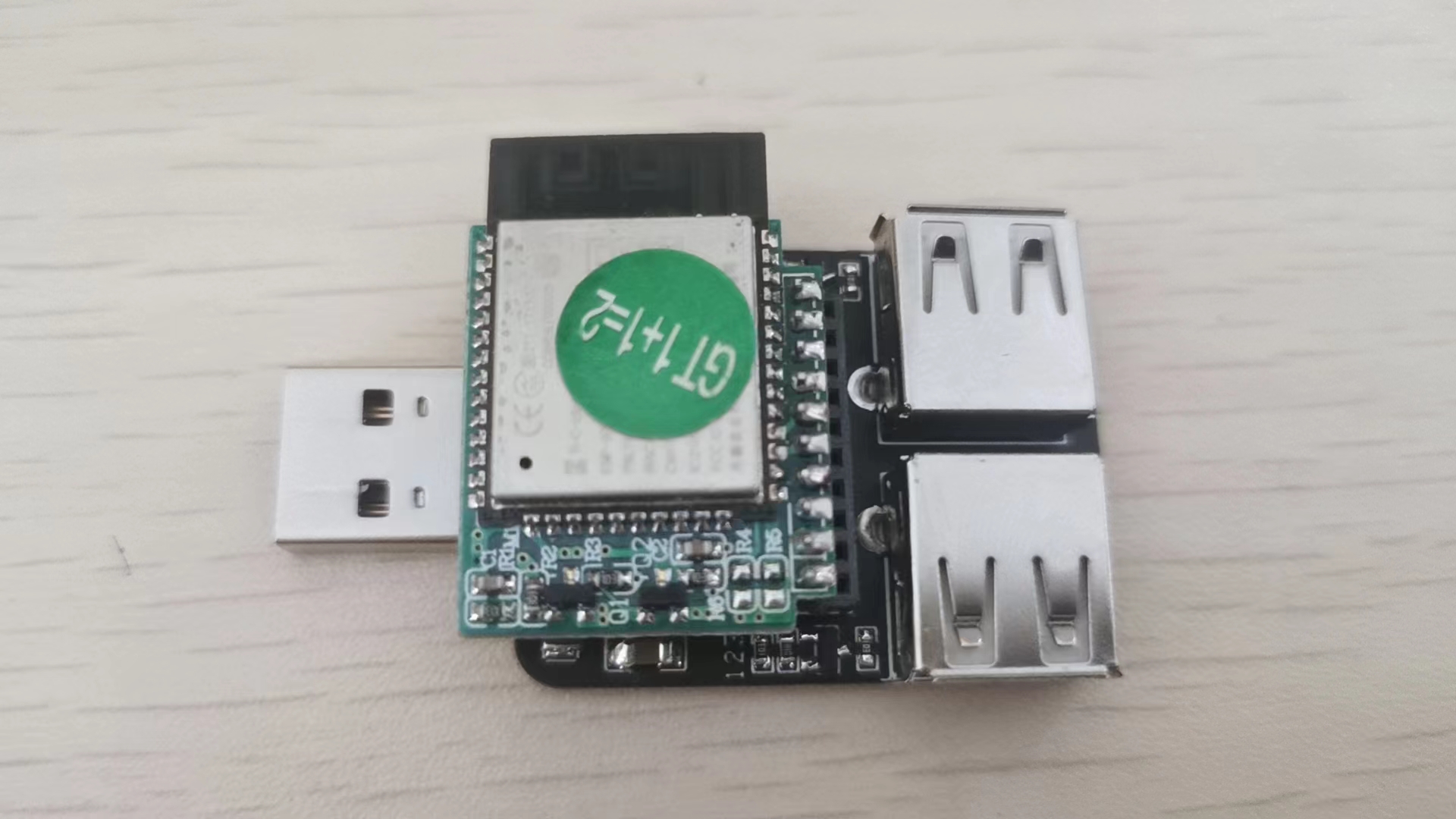
Feel free to use it however you like. I bought two LED lights and a USB flexible extension cable on Taobao and turned it into a smart plant light for my office. It works with the Mi Home app to set a timer to turn on the light every night.
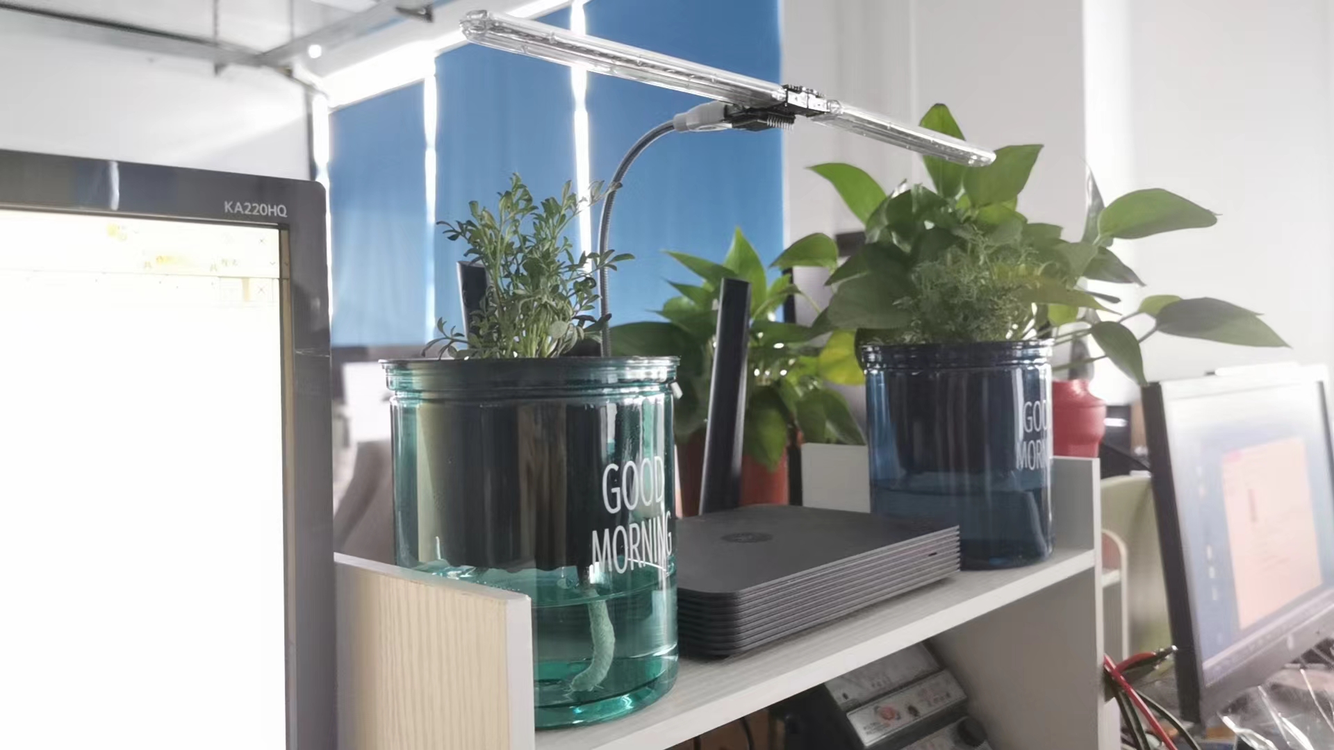
Taobao link: https://item.taobao.com/item.htm?_u=qbg2mqi23eb&id=604491282051&spm=a1z09.2.0.0.e9022e8dJ7c3Ve
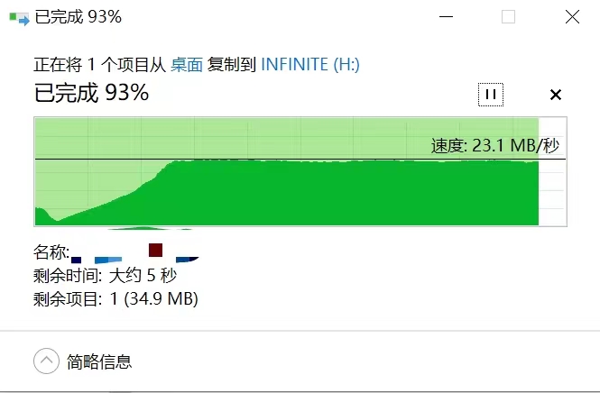
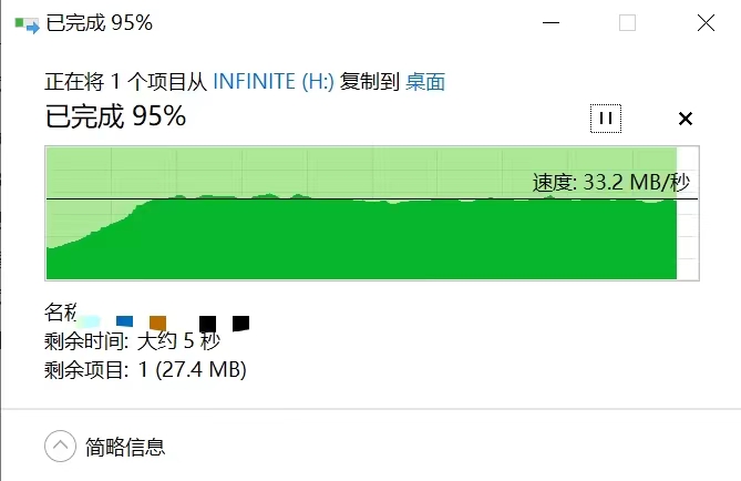
A custom USB 2.0 docking station based on the SL2.1A chip, tested and working well!
Computer to USB flash drive transfer speed:
USB flash drive to computer transfer speed:
The docking station's casing file can be downloaded from the attachment. The casing file has not yet been verified; however, the assembly does not appear to interfere with

the assembly cross-sectional view.

USB docking station casing.STL
USB docking station baseboard.STL
PDF_USB2.0 Dock.zip
Altium_USB2.0 Dock.zip
PADS_USB2.0 Dock.zip
95947
MIPI screen adapter board for NanoPC-T4
Convert the NanoPC-T4's MIPI-DSI interface to a universal 31-pin MIPI interface and include a touch screen.
The project has been tested and is working properly.
The MIPI interface has many proprietary pin definitions; please double-check the screen and interface definitions for compatibility before use!
Different screens may have different backlight voltages and currents; compatibility with the project's backlight control chip must be confirmed!
After comparing with the pin definitions of the Taishanpai development board, the touch interface in this project does not have common pin definitions!
After comparing with the pin definitions of the Taishanpai development board, the MIPI-Logic power supply in this project is 1.8V, which may cause incompatibility issues!
The screens supported by this project are: HDMI to MIPI driver board, signal adapter board, DSI LCD screen, Raspberry Pi, support for touch industrial robots - 31-pin high-brightness screen from Taobao (taobao.com). Through negotiation with the seller, a GT911 surface mount touchscreen is available.
The project uses a 1.2mm board thickness, a JLCPCB 7628 stack-up structure, a minimum trace spacing of 6mil, and uses adjacent inner layers as reference planes for routing, strictly adhering to differential pair routing and return path principles to maintain impedance matching.
The LED constant current section uses the LGS63030. The dimming signal is filtered by a first-stage RC filter to ensure analog dimming. Alternatively, the capacitor can be removed to use PWM direct drive, or the LGS63032 chip can be used, which is more compatible with PWM dimming.


PDF_MIPI Screen Adapter Board for NanoPC-T4.zip
Altium MIPI Screen Adapter Board for NanoPC-T4.zip
PADS_MIPI Screen Adapter Board for NanoPC-T4.zip
BOM_MIPI Screen Adapter Board for NanoPC-T4.xlsx
95948
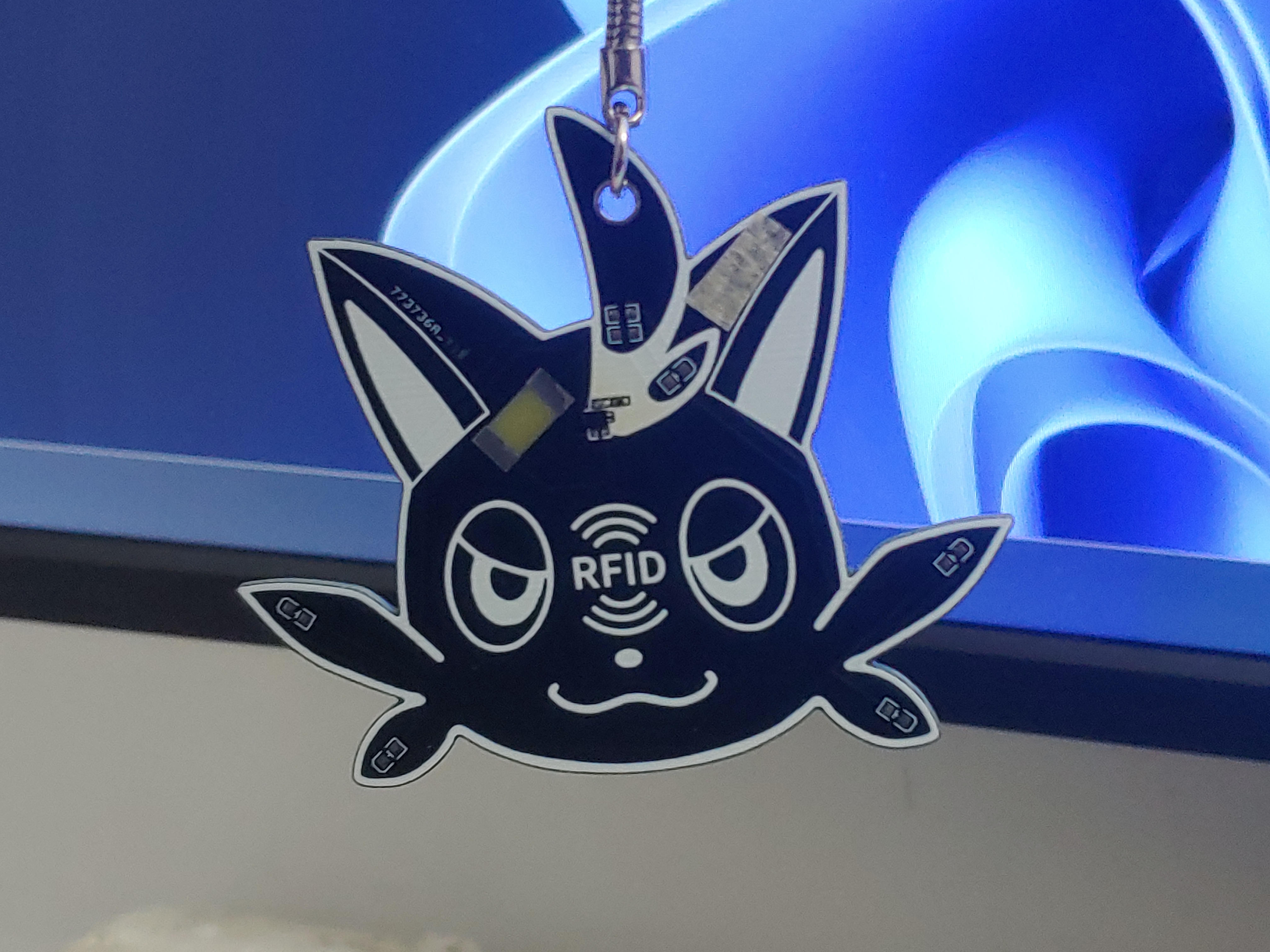
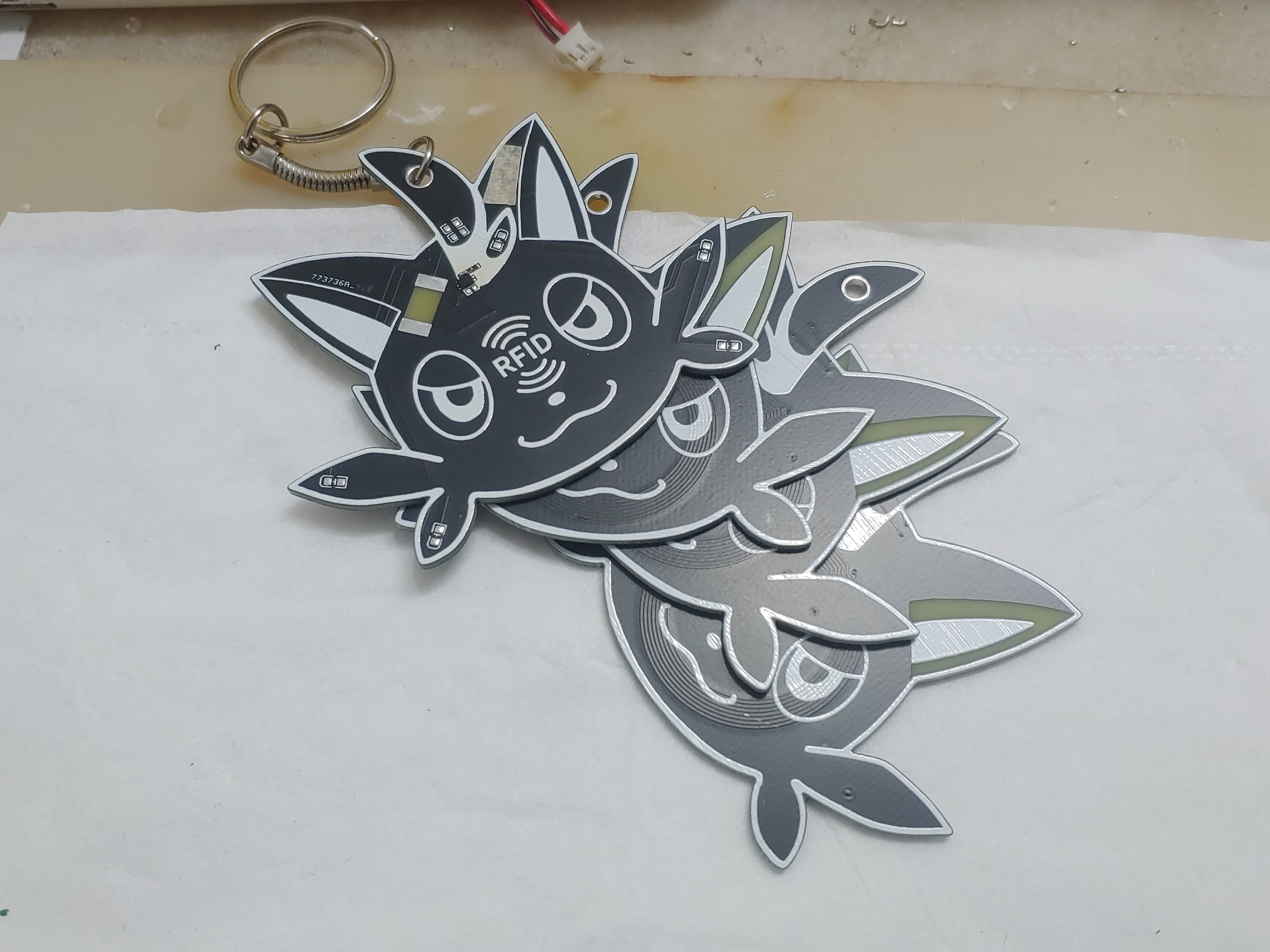
Paluka, the Mischievous Cat NFC
Two options are used: one is NT2H1311F0DTLH, and the other is a COB package, plus two 50-ohm resistors and five LEDs. The appearance is inspired by the Mischievous Cat from "Phantom Beasts Palu".
Using a professional EDA design, removing the identification chip allows it to function as a wireless charger indicator card, NFC card reader status indicator, etc.
![20240223_230249_Burst01.jpg]
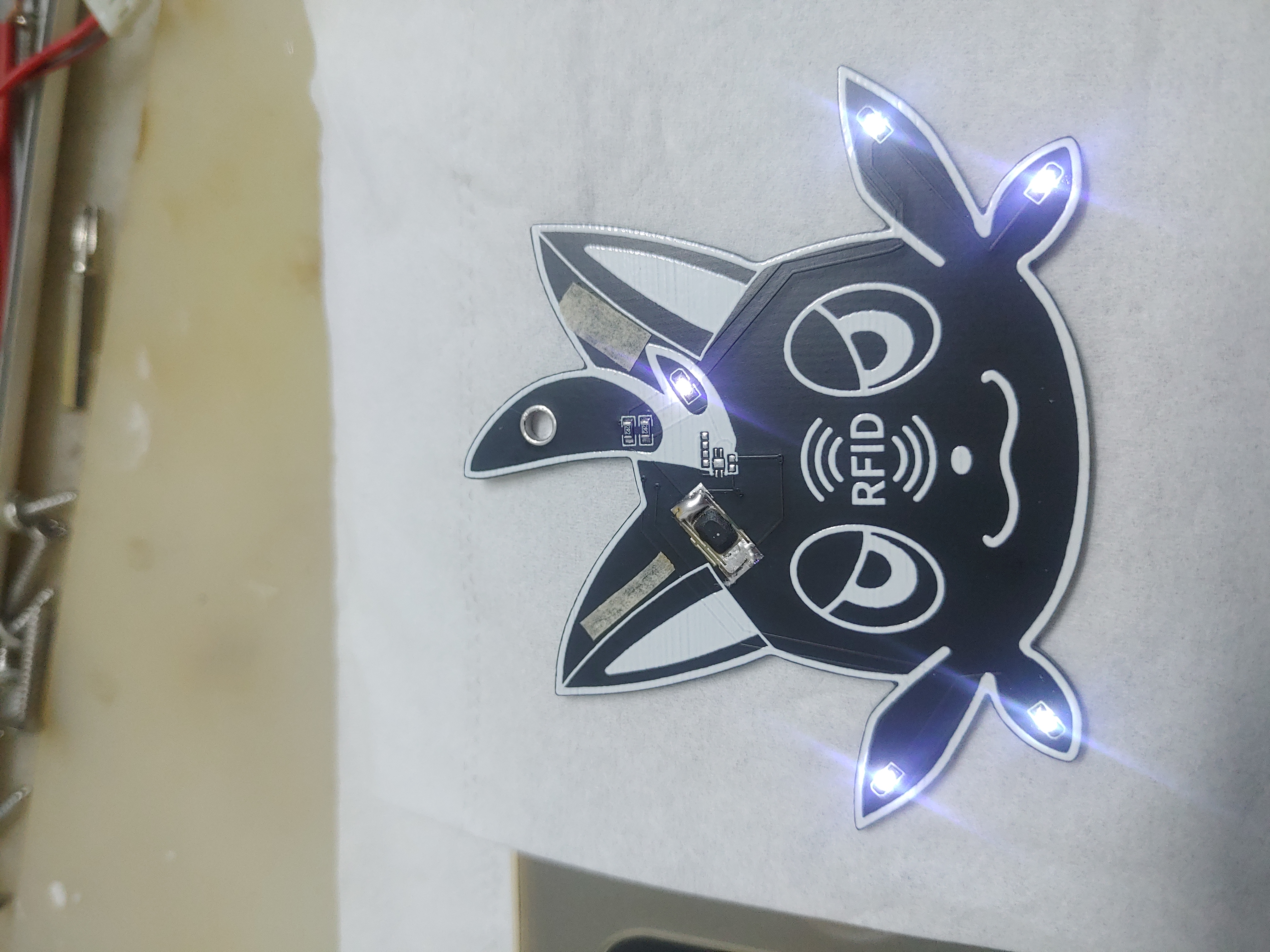
Usage effect, COB solution
![20240224_005449.jpg]
NT2H1311F0DTLH solution
![20240224_011328.jpg]

![20240224_011001.jpg]
20240223_224834.mp4
PDF_Paluka, Mischievous Cat NFC.zip
Altium_Paluka, Mischievous Cat NFC.zip
PADS_PALUKA, Mischievous Cat NFC.zip
BOM_Paluka, Mischievous Cat NFC.xlsx
95950
NE555 array dual-pulse generation module
4-string NE555 pulse generator
This is a 4-series NE555 pulse generator with adjustable pulse widths of 0.1-1ms and 1-10ms, suitable for spot welding machines. The key is triggered by a falling edge;
the first 555 has a 500ms delay, the second is a pre-welding pulse, the third is a delay pulse, and the fourth is the welding pulse. The outputs of the second and fourth 555s are connected to the pulse output via diodes.
PDF_NE555 Array Dual-Pulse Spot Welding Machine Pulse Generation Module.zip
Altium_NE555 array dual-pulse spot welding machine pulse generation module.zip
PADS_NE555 Array Dual-Pulse Spot Welding Machine Pulse Generation Module.zip
BOM_NE555 Array Dual-Pulse Spot Welding Machine Pulse Generation Module.xlsx
95951
RH6618A PWM Touch-Controlled Dimmable LED Light
A 20-lamp single-channel touch-controlled PWM dimming lamp using the Ronghe RH6618 as the main control chip.
First, it was all theoretical. I spent a long time searching for a good controller, finally choosing the RH6618. This solution can be bought on Taobao for around one yuan. Its PWM frequency is over 24kHz, significantly higher than the 4kHz of solutions like the JL8022W (I heard, it wasn't mentioned in the datasheet), and also several times more expensive QAQ. Hopefully, 24kHz will be easier on the eyes than 4kHz.
Since the LED is intended to provide supplemental lighting for the camera during soldering, I just chose a random LED, which looks passable. At maximum brightness, before heating up, the power consumption is just over 2W; it will increase slightly as the temperature rises. The aluminum substrate heats up well; in an indoor temperature of 20 degrees Celsius, the board feels warm to the touch.
tmp.mp4
PDF_RH6618A PWM Touch-Controlled Dimmable LED Lamp.zip
Altium_RH6618A PWM Touch-Controlled Dimmable LED Lamp.zip
PADS_RH6618A PWM Touch-Controlled Dimmable LED Lamp.zip
BOM_RH6618A PWM Touch-Controlled Dimmable LED Lamp.xlsx
95952
USB to Serial Port - CH340 Serial Port Programmer
USB to serial adapter, and automatic programming circuitry for ESP8266 and ESP32 low-end systems.

PDF_USB to Serial Port - CH340 Serial Port Programmer.zip
Altium_USB to Serial Port - CH340 Serial Programmer.zip
PADS_USB to Serial Port - CH340 Serial Port Programmer.zip
BOM_USB to Serial Port - CH340 Serial Port Programmer.xlsx
95953
electronic


 京公网安备 11010802033920号

 APL5708R-21VC-TR


