This system uses two unipolar HAL3144E switching Hall sensors (6x3 magnets), two
0.5mm diameter, 13mm diameter, and 30mm long springs (with seals removed
) as a multi-color printing dual extruder buffer. It outputs two position signals to the main board. The default high-level output
acts as a sensor for active filament rewinding, directly driving the rewind motor (using an AO3400 MOSFET). For low-level control, I ultimately chose the Tuozhu P1+AMS. This component wasn't actually installed on the machine for testing; refer to the Tuozhu AMS buffer.
Attached are test videos and photos of printed models/explosion heads.
A typical 3D printer group: 701827620

Hall effect version buffer not verified on-device.zip
PDF_3D Printer Consumables Buffer - Active Rewind Rack Sensor.zip
Altium_3D Printer Consumable Buffer_Active Rewind Rack Sensor.zip
PADS_3D Printer Consumable Buffer_Active Rewind Rack Sensor.zip
BOM_3D Printer Consumables Buffer_Active Rewind Feeder Sensor.xlsx
95983
PY32F002BF15P6TU Minimum System Board
PY32F002BF15P6TU Minimum System Board
A small system board was built using a cheap microcontroller, the PY32F002BF15P6TU, based on someone else's PY32F002A. It's easy to integrate and has been verified to be working correctly. It has
24K ROM, 3K RAM, 24M bandwidth, and a 12-bit ADC.
Development tools include Keil, and programming can be done with ST-Link. The development kit can be found on the official website.
PDF_PY32F002BF15P6TU Minimum System Board.zip
Altium_PY32F002BF15P6TU Minimum System Board.zip
PADS_PY32F002BF15P6TU Minimum System Board.zip
BOM_PY32F002BF15P6TU Minimum System Board.xlsx
95984
TTL_CH340N
TTL based on CH340N
Compact TTL, based on CH340N, with backflow protection and computer USB port protection, already verified.
PDF_TTL_CH340N.zip
Altium_TTL_CH340N.zip
PADS_TTL_CH340N.zip
BOM_TTL_CH340N.xlsx
95986
USB power distribution board
To address the shortage of USB outlets in dormitory rooms, a USB power distribution board was designed and manufactured. It includes a main switch, four independent switches, five indicator lights, and filtering capacitors. It can power multiple low-power USB devices.
To address the shortage of USB plugs in dormitories, a USB power distribution board was designed and manufactured. It includes a main switch, four independent switches, five indicator lights, and filtering capacitors. It can power multiple low-power USB devices and has successfully solved the power supply problem for low-power devices in dormitories.
The innovation lies in using copper pillars to connect the upper and lower panels, creating a sandwich effect. The main components are soldered to the front of the middle panel, while the filtering capacitors are located on the back. A backplate prevents short circuits caused by hand contact, and a front cover facilitates easy plugging and unplugging. Two panels are used to accommodate the screw length of the copper pillars. I used a 1.6mm thick board for better mechanical strength. The copper pillars are 10+4mm for reference.
To prevent electrostatic discharge, the input of this power distribution board (USB A male connector) is not grounded. The switch housings are also not grounded.
Note that the light-transmitting window next to the LEDs is live.
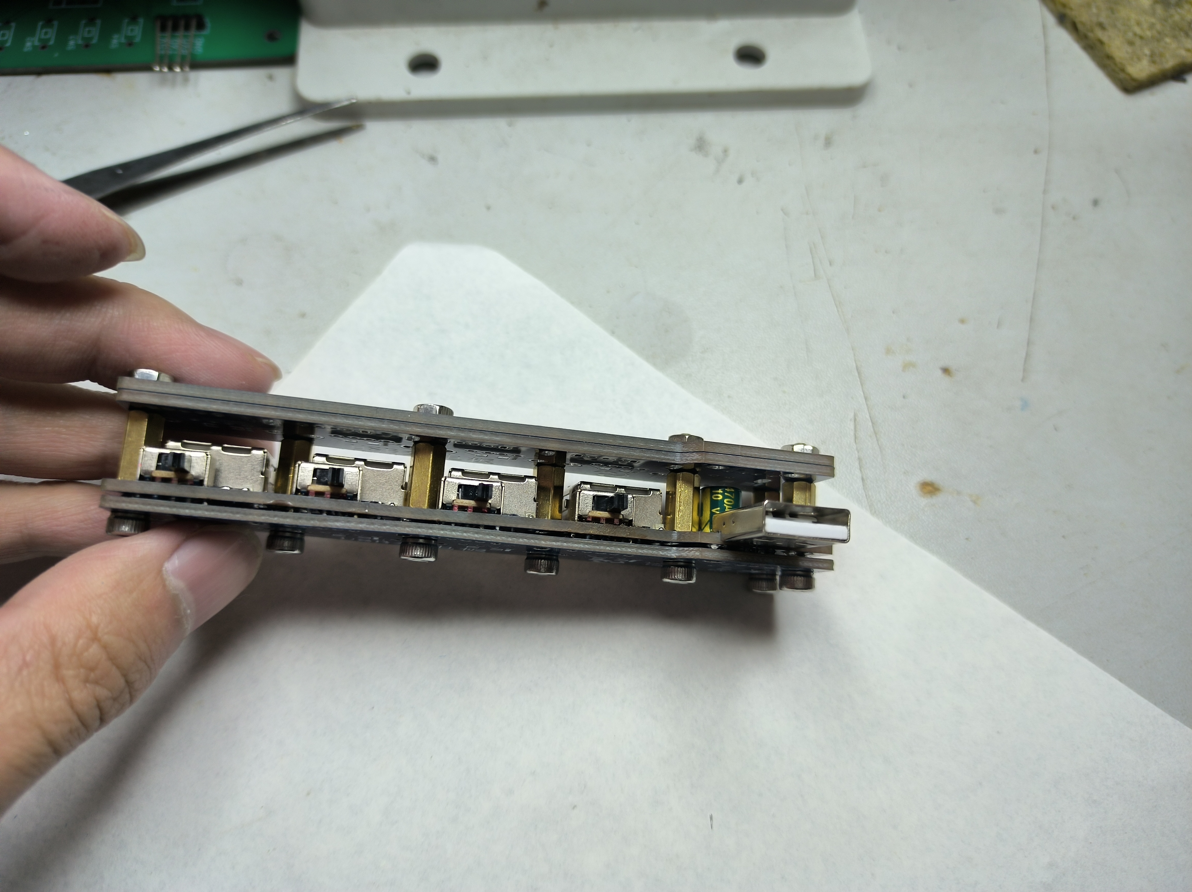
It is quite heavy.
IMG_20240225_224601.jpg
VID_20240225_164009.mp4
PDF_usb distributor board.zip
Altium_usb distributor board.zip
PADS_usb power distributor.zip
BOM_usb power distribution board.xlsx
95987
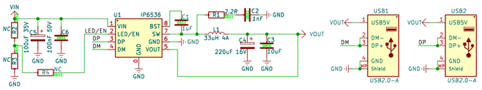
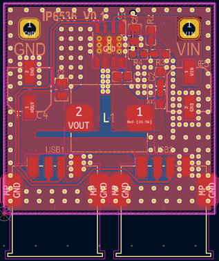
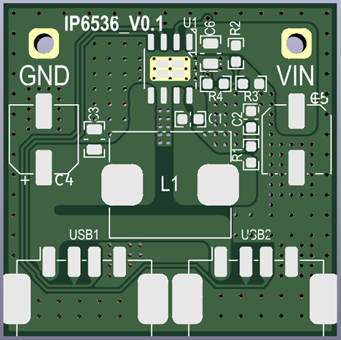
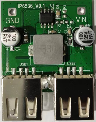
IP6536-AA-15W Car Charger/Discharger
8~32V input, car charging/discharging chip, 5V 3.1A AA output (maximum total output current 3.1A).
Functional Description:
8~32V input, car charging/discharging chip, 5V 3.1A output (maximum total output current 3.1A).
Input voltage:
8~32V. 40V Max.
Output ports:
USB-A, USB-A
output power
5V 3.1A;
Switching frequency
150KHz ;
Static power consumption
5mA;
Chip over-
temperature protection built-in, 150℃. Input
voltage : 12.01V 0.459A ; Output voltage : 1.000A 5.5W 92.56%; Output current : 11.92V 0.959A 5.096V 2.000A 11.4W 89.13%; Output current: 11.90V 1.562A 5.352V 3.000A 18.6W 86.33% ; Output current: 24.01V 0.233A 5.104V 1.000A 5.60W 91.24 %; Output current : 23.97V 0.478A 5.094V 2.000A. 11.46W 88.92% 23.95V 0.775A 5.349V 3.000A 18.56W 86.46% Operating Temperature Schematic PCB Layout Diagram PCB 3D Preview PCB Physical Image Download: https://oshwhub.com/saber.lily?tab=project&page=1 Other design files can be obtained from your supplier.

PDF_IP6536-AA-15W Car Charger/Discharger.zip
Altium_IP6536-AA-15W Car Charger/Discharger.zip
PADS_IP6536-AA-15W Car Charger/Discharger.zip
BOM_IP6536-AA-15W Car Charger/Discharger.xlsx
95989
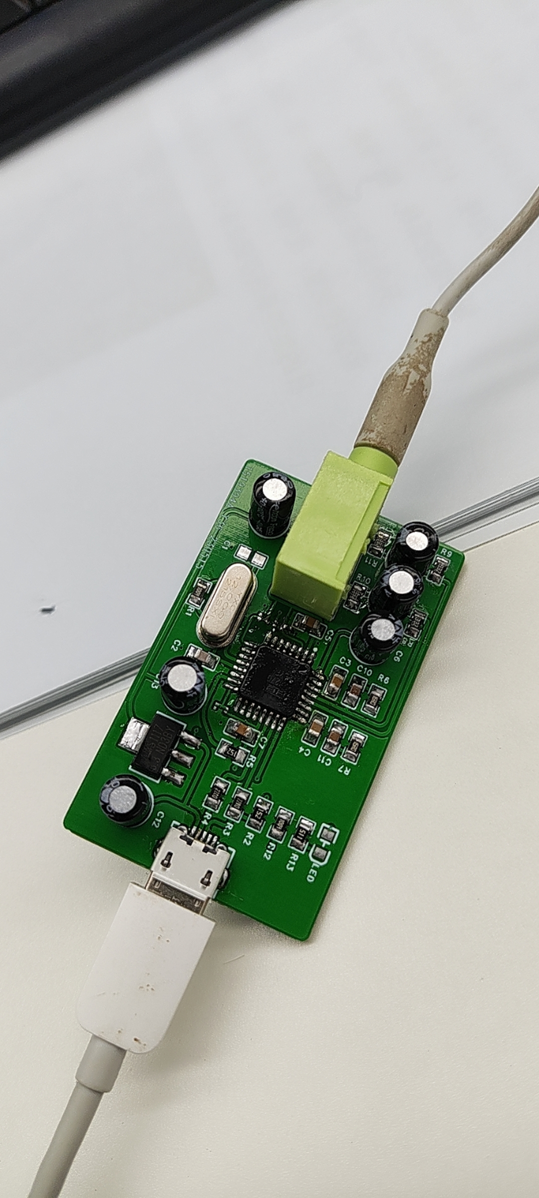
PCM2707 sound card
This is a USB sound card based on TI's PCM2707, featuring a 3.5mm headphone jack. It's compact, aesthetically pleasing, and practical, improving the quality of music playback on your computer. For discussion, please visit https://bbs.21ic.com/icview-3303016-1-1.html
The schematic diagram differs slightly from the final PCB; some pins and unnecessary external interfaces have been removed from the PCB.
PDF_PCM2707 sound card.zip
Altium_PCM2707 sound card.zip
PADS_PCM2707 sound card.zip
BOM_PCM2707 sound card.xlsx
95990
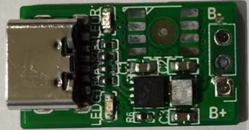
IP2311: Minimum Size Single-Cell Battery Switch Charging
With USB 5V input, switch charging, charging a single-cell battery, the battery terminal current is approximately 1-1.2A, and the charging power is approximately 5W.
The overall size of the charging circuit is close to that of a single SOP-8 chip
, perfectly resolving the contradiction between the insufficient charging current of the TP4054 and the excessive heat generation of the TP4056.
Function Description:
USB 5V input, switchable charging, charges a single-cell battery, battery terminal current approximately 1-1.2A, charging power approximately 5W.
Ultra-mini size; the overall size of the charging circuit is close to that of a single SOP-8 chip. The SOP-8
IP2311 perfectly addresses the contradiction in small-size products: the TP4054's charging current is too low, and the TP4056's heat generation is too high.
Input voltage:
4.5~5.7V, 18V Max. 4.5V triggers undervoltage protection, automatically reducing charging power.
Output voltage:
4.2/4.3/4.35/4.4V ±0.05V.
Trickle charging :
3.0V ±0.05V .
Full charge cutoff:
60mA (40-100mA). (When the chip output reaches 4.2/4.3/4.35/4.4V, if the battery terminal has not reached it, it switches from constant current charging to constant voltage charging. The higher the internal resistance of the battery cell and wires, the longer the constant voltage charging time.) Two
LEDs .
A red light illuminates during charging, turning green when fully charged.
NTC
does not support
chip over-temperature
protection; it has built-in over-temperature protection up to 140℃.
USB voltage,
USB current,
battery voltage
, battery current
, charging power,
charging efficiency:
4.90V
1.10A
, 3.66V
1.30A ,
5.42W
, 87.60% ;
4.90V
1.10A , 3.85V 1.25A , 5.43W , 88.55 %; 4.90V 1.10A , 4.06V 1.20A, 5.43W , 89.50%. Charging temperature . Schematic diagram, PCB layout, PCB 3D preview, PCB physical image . Download data: https://oshwhub.com/saber.lily?tab=project&page=1. Other design files can be obtained from your supplier.


Demo-IP2311_V0.1.pdf
Demo-IP2311_V0.1_240221_bom.csv
Demo-IP2311_V0.1_240221_gerber.zip
IP2311_datasheet_V1.00.pdf
PDF_IP2311: Minimum Size Single-Cell Battery Switch Charging.zip
Altium_IP2311: Miniature single-cell battery switch charger. (zip file)
PADS_IP2311: Minimum Size Single-Cell Battery Switch Charger.zip
BOM_IP2311: Minimum Size Single-Cell Battery Switch Charger.xlsx
95992
DC UPS module powered by lithium battery
Using the MP3428AGL-Z solution, the output is adjustable from 5V to 15V. Without a heatsink, it can withstand 12V 1.5A in a standby test without any problems. The lithium battery has a maximum charging current of 2.5A and includes battery protection.
Supports up to 2.5A lithium battery charging; without heat dissipation, operation is recommended to be below 20W.
The chip supports up to 18V; since the capacitor I used only has a voltage rating of 16V, if the parameters are the same, 15V or even lower is recommended.
It includes a battery protection chip for overcharge, over-discharge, overcurrent, and overload protection.


Actual test data without heat dissipation: (Currently, I only have a 5A switching power supply on hand, so I cannot test higher power outputs) Input
Voltage (Board End) Input Current Input Power Output Voltage (Board End) Output Current Output Power Efficiency 3.972V 1.73A 6.87W 12.2V 0.5A 6.1W 88.8% 3.832V 3.49A 13.374W 12.2V 1A 12.2W 91.2% 3.891V 4.84A 18.32W 12.2V 1.4A 17.08W 93.2% Testing Tools: Test method for ATZ9712 electronic load, ZT219 multimeter, and ordinary 30V 5A adjustable power supply : The input (output) voltage is measured using an ordinary multimeter, and the current is referenced from the adjustable power supply current display and the electronic load display parameters.
PDF_DC UPS Module Lithium Battery Powered.zip
Altium DC UPS Module Lithium Battery Powered.zip
PADS_DC UPS Module Lithium Battery Powered.zip
BOM_DC UPS Module Lithium Battery Powered.xlsx
95993
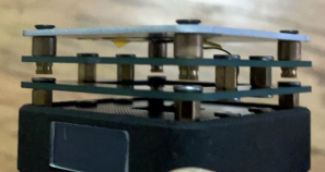
[PD Protocol | High-Quality Design] Mini Heating Platform [Copper Column Plate]
This project originated from the mini heating platform created by Xiao O and Xiao Q. The probes tend to burn out during prolonged electrical conduction, so we combined solutions from other developers and adapted them into a copper pillar conductivity solution.
Original Solution: [PD Protocol | High-Quality Design] Mini Heating Platform - JLCPCB EDA Open Source Hardware Platform (oshwhub.com)
1. The circuit BOM is consistent with the solutions for O and Q, no need to change the BOM or firmware. 2. The PCB needs to be completely redesigned. 3. Probes don't need to be purchased; instead, buy copper pillars and Teflon tubing. (Cheap and free shipping) Copper Pillars: 4*6*5 (10 pieces) Powder Metallurgy Copper Sleeve Oil-Including Bushing Brass Bushing Bearing Inner Diameter 3M 4M 5M 6M 8M 10M 12M 14M 16-60-tmall.com Tmall
Teflon Tubing: 3*4 mm Teflon Tubing Milky White PTFE Tubing Hard PTFE Flexible Hoses Corrosion Resistant Acid and Alkali Resistant High Temperature Polytetrafluoroethylene Tubing -tmall.com Tmall
Countersunk Screws: Iron-plated black Phillips head flathead screws, countersunk bolts, machine-threaded screws, KM electronic small screws M2 M3 M4 M5 M6 - tmall.com (Tmall).
Important note: If you can make countersunk holes for the heated aluminum substrate (you'll need to buy a countersunk drill), buy screws of specification [M3*10, 4.5mm head]. Otherwise, buy screws of specification [M3*12]... otherwise they won't be long enough.
4. Assembly method
is otherwise the same as the original plan, key points...

PDF_[PD Protocol_ High-Quality Design] Mini Heating Platform [Copper Column Plate].zip
Altium_[PD Protocol_ High-Quality Design] Mini Heating Platform [Copper Column Plate].zip
PADS_[PD Protocol_ High-Quality Mini Heating Platform [Copper Column Plate].zip
95997
TL431 heating control board
It enables heating and temperature control of external heating wires or aluminum substrates that control the resistance of wiring.
Principle: Temperature is detected by an NTC sensor, and two TL431 microcontrollers are used to determine the upper and lower temperature limits. Two NOR gates form a latch.
Function: To achieve range-based temperature control.
Operating Conditions: 5V power supply from a Vivo phone charger (the power supply to the external heater should not exceed the output power of the phone charger). Phenomenon: Two LEDs on the board indicate whether the current temperature exceeds the set upper and lower temperature limits. Issue
: The safety of the pre-amplifier power supply needs to be verified by the user. Power from a phone power bank is generally safer, but the power consumption must be carefully monitored.
8KB2(R4J6%M$MO36WVR%N2I_tmb.jpg
PDF_TL431 heating control board.zip
Altium_TL431 heating control board.zip
PADS_TL431 heating control board.zip
BOM_TL431 Heating Control Board.xlsx
95999
electronic


 京公网安备 11010802033920号

 21512-61


