Six-segment LED display clock
demonstration video
I. Current situation
Using a microcontroller to drive a digital tube for time display is a very basic project for every electronics enthusiast. Imaginative creators can always come up with all sorts of tricks to display time. I saw a project before that used ceramic filaments combined with tm1637 and driven by a microcontroller. I really like the warm feeling brought by ceramic filaments, and the projects of predecessors have also given me a lot of inspiration [1][2][3]. But I think that since we don't use the pre-packaged digital tube, why not put some effort into the digital tube? Inspired by Teacher 6o (doge), [4] I found that a six-segment LED display can also display all the numbers. Based on this, I did the following work.
II. Basic Functions:
The program is written in MicroPython and WebRePL mode is enabled, allowing for online program uploads;
it connects to Tencent Cloud ATP for network time synchronization;
the TM1637 library is modified, primarily for the digital display, temperature display, and time display, enabling correct display of time and temperature using a four-digit six-segment LED display;
a DS18B20 temperature detection module detects and displays the current temperature every 30 seconds;
the lights automatically turn off when the time reaches midnight to avoid disturbing sleep. III.
Innovations: The control circuit board and display circuit board are separated, allowing for separate debugging and display functions, and future expansion of the number of digits is possible;
Type-C power is used;
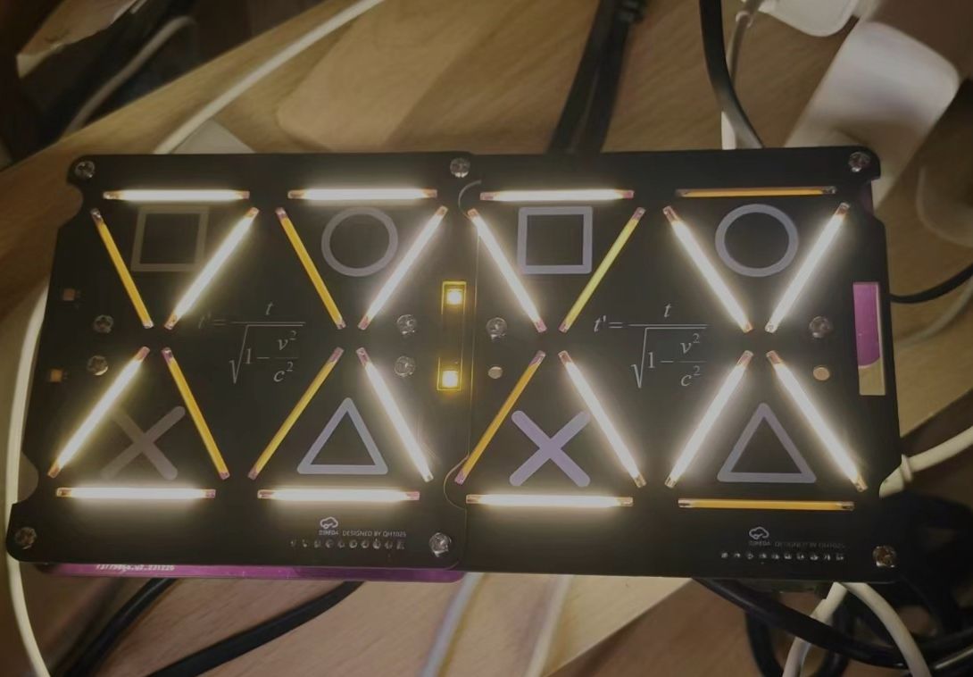
Sony's unique button logo and the formula for clock dilation are drawn on the display panel;
the circuit board size does not exceed 10cm × 10cm for easy access;
the circuit board has openings for assembly using M3 screws. Future work will focus on
improving the circuit design. Currently, the control circuit board uses pin headers to connect the 8266 development board; in the future, it can be integrated onto the circuit board for a thinner and lighter design; a third set of pin headers for the LED display will be added to increase expandability. Ideally, a flexible flat cable should be used; the current DuPont wire connections are somewhat inelegant.
The program design needs improvement. The current time display is not mature enough (it's inaccurate, possibly due to time dilation; P). More IoT functions need to be added. Both the camera and the naked eye can see noticeable flicker; we need to investigate the problem.
Since it's already connected to the network, consider creating a small program that allows for customizable light-off times and brightness adjustments.
There's a button planned in the circuit, but its function isn't implemented yet; future program modifications could allow it to turn the light on/off and adjust brightness.
The overall brightness is very high; although paper can be used to block it, the designed pattern becomes invisible. We'll consider software or hardware solutions later. This is my
first time open-sourcing a small gadget I made, and it's written like a thesis—I wonder if it's too long. This project still has much to improve; I won't post the program for now. I think the main highlight is the six-segment display; I hope everyone can find their own creative ways to use it!


 京公网安备 11010802033920号

 MMBD4148CA


