This project started because my classmate's sister wanted my classmate to make a USB flash drive for her, but she subcontracted it to me and asked me to open-source it. The solution is simple: the classic GL823K design.
After completion, the appearance remains basically unchanged. When plugged in, the "C" indicator lights up, and the "T" indicator flashes during data transfer, supporting OTG. The
board should roughly look like this (PDD's generic USB flash drive section says it's very professional).
Place the board like this, don't install it backwards. The board should be 1mm or 0.8mm thick, but the Type-C port should be 1.6mm to better utilize space.
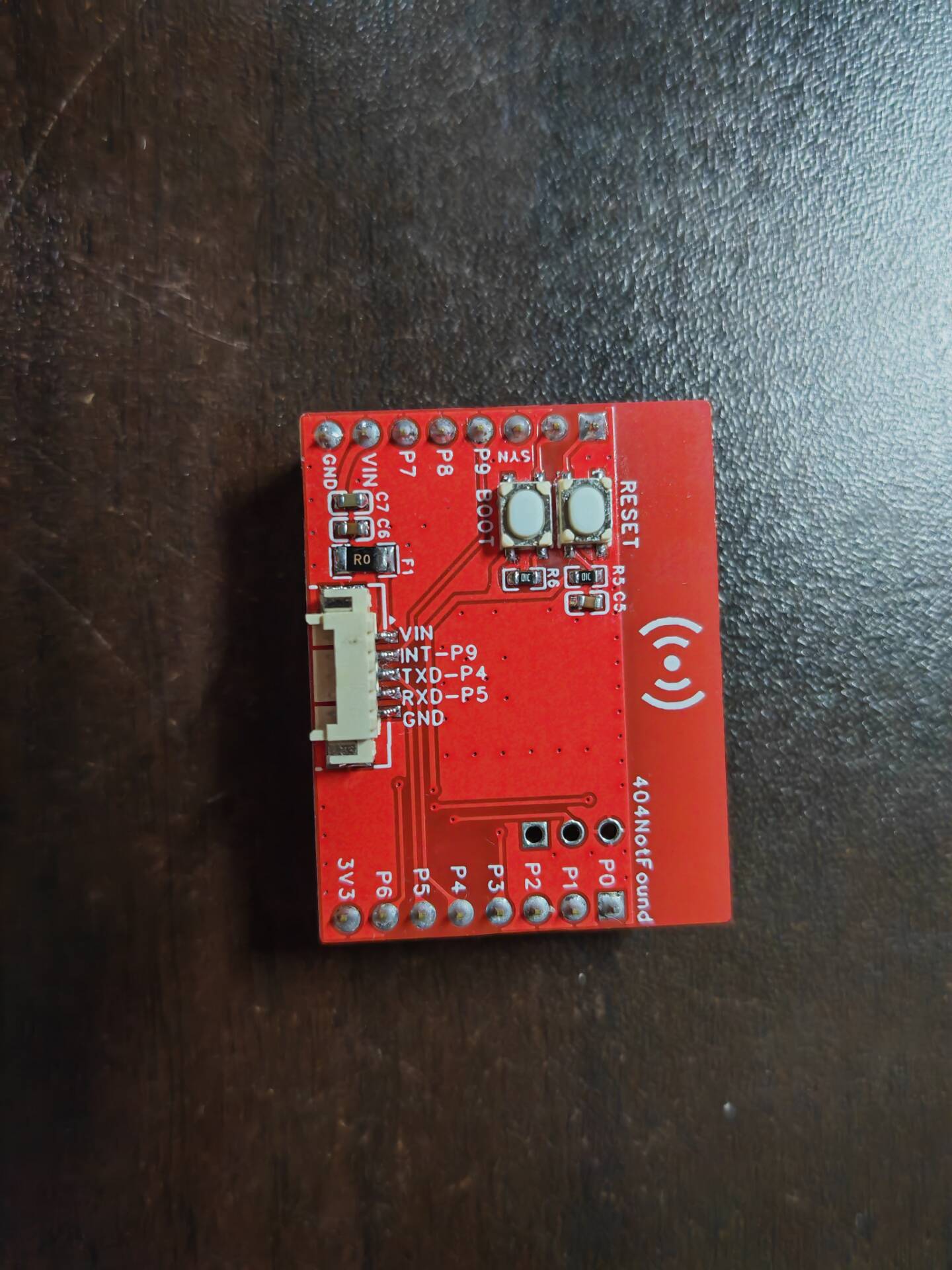
Verified, the schematic is the same as the official one, with an additional serial port, and also includes boot and reset buttons. I recommend finding the ATWINC1500 module on Xianyu (a second-hand marketplace), where one module should cost around 35 RMB or less.
PDF_OpenMv-WiFi module.zip
Altium_OpenMv-WiFi module.zip
PADS_OpenMv-WiFi module.zip
BOM_OpenMv-WiFi module.xlsx
96077
Electronic clock design based on STC8H1K08
This paper presents the design of an electronic clock system based on the STC8H1K08 microcontroller. The design includes clock display, timekeeping, and chime functions.
1. Engineering Principle: The electronic clock utilizes an STC8H1K08 microcontroller to control various display devices (such as LED digital tubes or LCD screens). It uses internal timer and counter modules for precise timing and external input devices (such as buttons) to set the time and alarm functions. Through proper programming and peripheral connections, it achieves time display, timing, and chime functions.
2. Function: The electronic clock's function is to accurately display time, provide timing and chime functions, and offer convenient time information to users. 3.
Operating Conditions:
Power Supply: The STC8H1K08 operates within a voltage range of 2.4V to 5.5V; therefore, the electronic clock's operating conditions must meet this voltage range.
Ambient Temperature: The STC8H1K08 typically operates within a temperature range of -40°C to 85°C; therefore, the electronic clock's operating environment should be within this temperature range.
PDF_Electronic Clock Design Based on STC8H1K08.zip
Altium_Electronic Clock Design Based on STC8H1K08.zip
PADS_Electronic Clock Design Based on STC8H1K08.zip
BOM_Design of an electronic clock based on STC8H1K08.xlsx
96078
Shandong University logo NFC card
School badges of Shandong University and other universities
For instructions on how to create the project, please refer to this project: https://oshwhub.com/KirinE/NFCbing-dun-dun-xue-rong-rong
PDF_Shandong University Emblem NFC Card.zip
Altium_Shandong University Emblem NFC Card.zip
PADS_Shandong University Emblem NFC Card.zip
BOM_Shandong University Emblem NFC Card.xlsx
96080
Wideband small loop antenna
PCB traces act as coils, forming a small loop antenna.
The PCB traces act as coils, with an inductance of approximately 440uH calculated in simulations, equivalent to a ferrite rod antenna. However, due to the low self-resonant frequency, it is estimated that above the self-resonant frequency, it will function as an electric field antenna, also providing some gain.


PDF_Broadband Small Loop Antenna.zip
Altium_wideband small loop antenna.zip
PADS_Wideband Small Loop Antenna.zip
BOM_Wideband Small Loop Antenna.xlsx
96082
Intelligent vehicle TC264 motherboard V1.2
This motherboard was specially prepared for the 2023 Intelligent Vehicle Extreme Off-Road Group. It was designed in my second year of university and has some minor flaws, but they do not affect its use. It is modeled after the official motherboard and is intended as a reference for other groups in the next Intelligent Vehicle competition.
This motherboard was specially designed for the 2023 Intelligent Vehicle Extreme Off-Road Group. It was designed during my sophomore year and has some minor flaws, but these do not affect its use. The design is modeled after the official motherboard and is provided for reference by other groups in the next Intelligent Vehicle competition. Major components can be directly imported and ordered from the LCSC online store. I recommend buying a resistor and capacitor kit; it will save you a lot of trouble.
PDF_Intelligent Car TC264 Motherboard V1.2.zip
Altium_Smart Car TC264 Motherboard V1.2.zip
PADS_Smart Car TC264 Motherboard V1.2.zip
BOM_Intelligent Vehicle TC264 Motherboard V1.2.xlsx
96084
EDP screen adapter board for NanoPC-T4
Convert the NanoPC-T4's custom EDP interface to a universal 30-pin EDP.
The project has been tested and is working properly.
The LCSC prototype is 1.2mm thick, using a JLCSC 7628 structure. The minimum line spacing is 6mil.
**Note:** Pay close attention to the orientation of the EDP ribbon cables at both ends!!!
**Note:** Pay close attention to the orientation of
the EDP ribbon cables at both ends!!! **Note:** Pay close attention to the orientation of the EDP ribbon cables at both ends!!!
Don't ask me how I know this…
The specific type of ribbon cable used depends on your screen; I used two correctly aligned ribbon cables this time.
The resistors soldered on the PCB are pull-up resistors for the EDP AUX channel. During debugging, because the NanoPC-T4 board had them but they weren't installed, I added them;

in practice, they weren't needed. There was a very frustrating experience when adapting the device tree. The FriendlyARM 4.19 kernel source code had significant compatibility issues with the T4, and there was absolutely no software support. As a beginner, I struggled for a very long time. Either the screen backlight wasn't working and the panel displayed normally, or the backlight was working but the panel wasn't. I especially want to complain about FriendlyARM's software support. I applied to four support groups and only got into two after a month, and those groups were completely inactive with no replies or daily chat.
Finally, I discovered, to my dismay, that FriendlyARM automatically turns off the backlight after recognizing the panel, requiring manual activation! No matter how absurd this is, it actually works. Finally, I wrote a shell script and placed it in the system startup directory to "manually" turn on the backlight at startup...
Finally, the screen lit up and I got to the desktop. The white bars were because the screen was defective; after replacing the screen, it returned to normal.
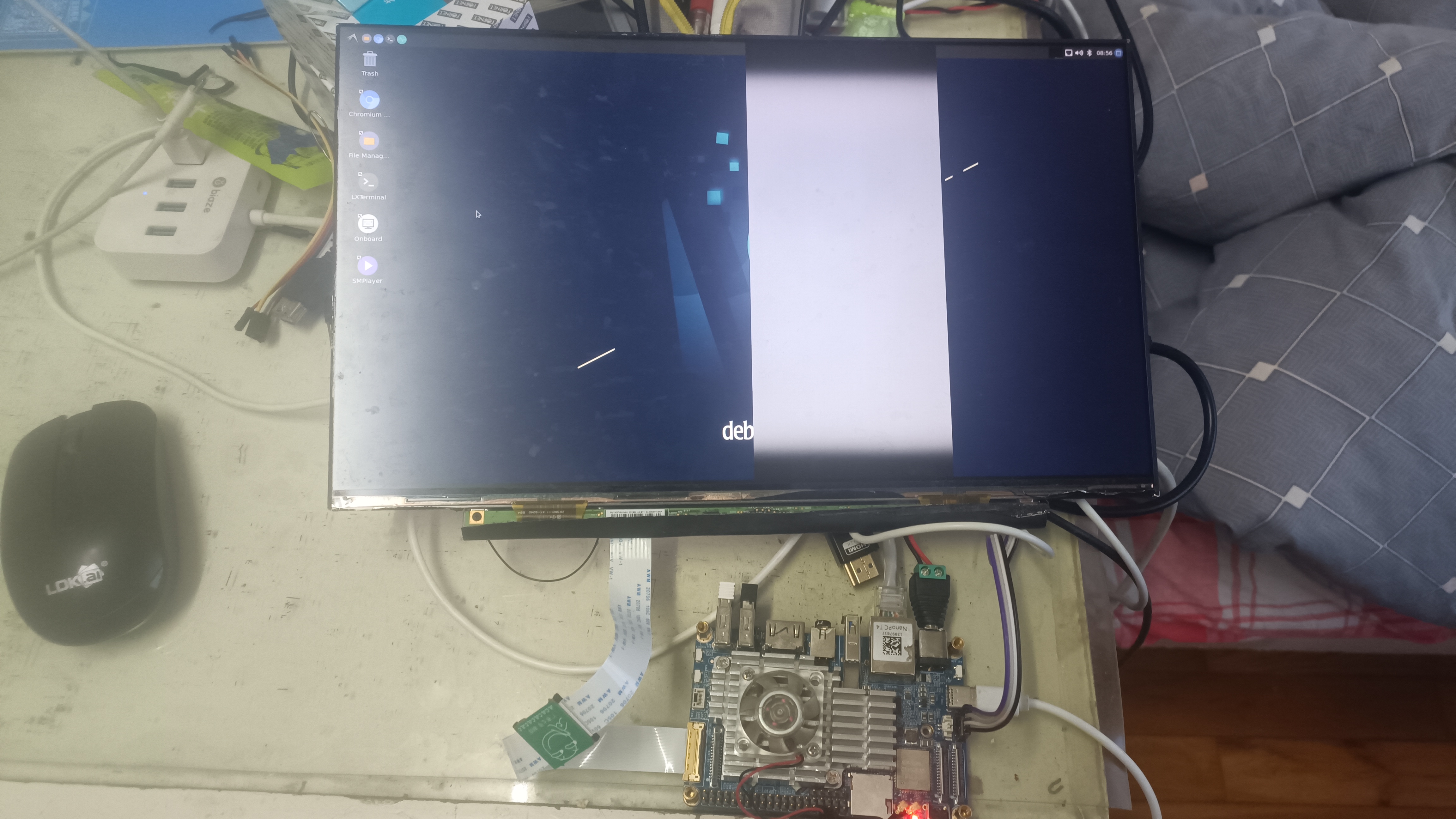
Finally, here's a picture of Genshin Impact using an adapter (doge).

PDF_EDP Screen Adapter Board for NanoPC-T4.zip
Altium EDP Screen Adapter Board for NanoPC-T4.zip
PADS_EDP Screen Adapter Board for NanoPC-T4.zip
BOM_EDP Screen Adapter Board for NanoPC-T4.xlsx
96086
6-inch MIPI screen_King3399 driver board
A 6-inch MIPI screen driver board for the KING3399 development board, priced at 39.9 RMB on Xianyu (a Chinese online marketplace).
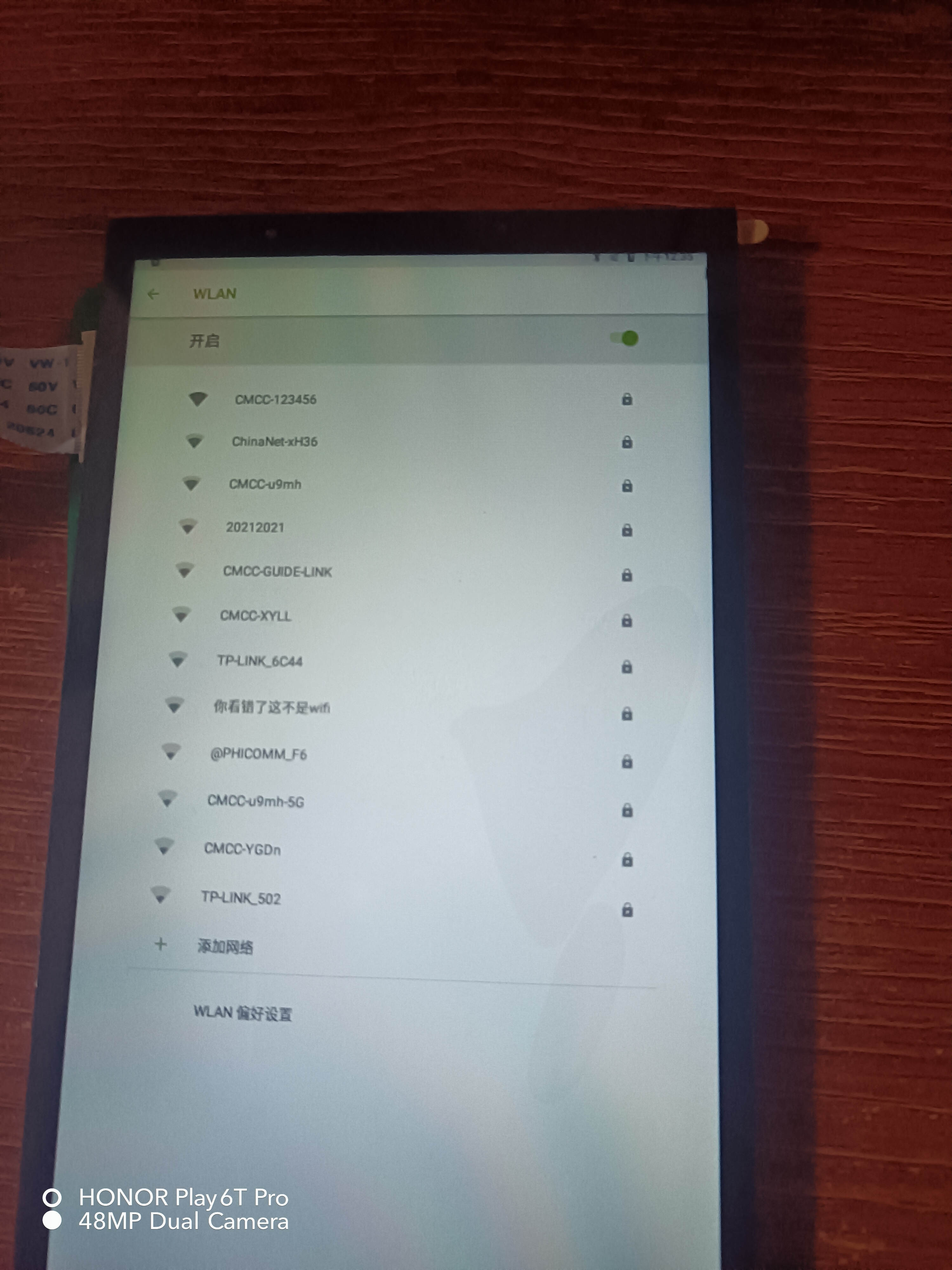
Please join group 290182516 to obtain the Android firmware (it's too large to upload), or compile it yourself. The DTS file has been released;
if you can't see the preview image, open it in the editor in the upper right corner.
rp-lcd-mipi-6-720-1280.dtsi
PDF_6-inch MIPI Screen_King3399 Driver Board.zip
Altium 6-inch MIPI screen King3399 driver board.zip
PADS 6-inch MIPI Screen King3399 Driver Board.zip
96087
Intelligent car design based on LCSC Liangshan School
Intelligent car design based on Liangshan School
The goal is
to familiarize oneself with the development process of embedded projects and master the ability to design hardware circuits, software programming, and system debugging for a smart car.
Functions include
: 1. Independent lithium battery charging circuit: The battery can be charged by plugging it into the TYPE-C port after the car is powered off.
2. Two-channel tracking module: Two infrared reflection detectors detect black lines for tracking.
3. Motor control chip: The motor can be controlled in four modes—forward, backward, braking, and hovering—by outputting high and low levels from two I/O ports of the microcontroller. Speed can also be adjusted via PWM control.
4. Power conversion circuit: Converts the 7.4V output from the lithium battery to 5V to power the microcontroller and includes a power switch to turn the car on and off.
5. Wireless and Bluetooth module: Enables remote control of the car's movement via wireless and Bluetooth modules. The wireless module can be used for 2.4G wireless control, and Bluetooth can be used for mobile phone control.
6. Buzzer: Uses a buzzer for warnings, such as in conjunction with a battery indicator to indicate low battery or in conjunction with an ultrasonic module to warn of obstacles ahead.
Skills acquired include
: learning how to efficiently read datasheets, consult relevant materials, and learn bug fixing techniques, with a focus on the process of finding information and fixing bugs.
The problem encountered was
that Keil did not recognize the dap file and used DFU for flashing.
98b7032f4a0f82cc0fda89a30c7d4338.mp4
PDF_Intelligent Car Design Based on LCSC Liangshan School.zip
Altium_Intelligent Car Design Based on LCSC Liangshan School.zip
PADS_Intelligent Car Design Based on LCSC Liangshan School.zip
BOM_Design of a Smart Car Based on LCSC Liangshan School.xlsx
96088
electronic
 board should roughly look like this (PDD's generic USB flash drive section says it's very professional).
 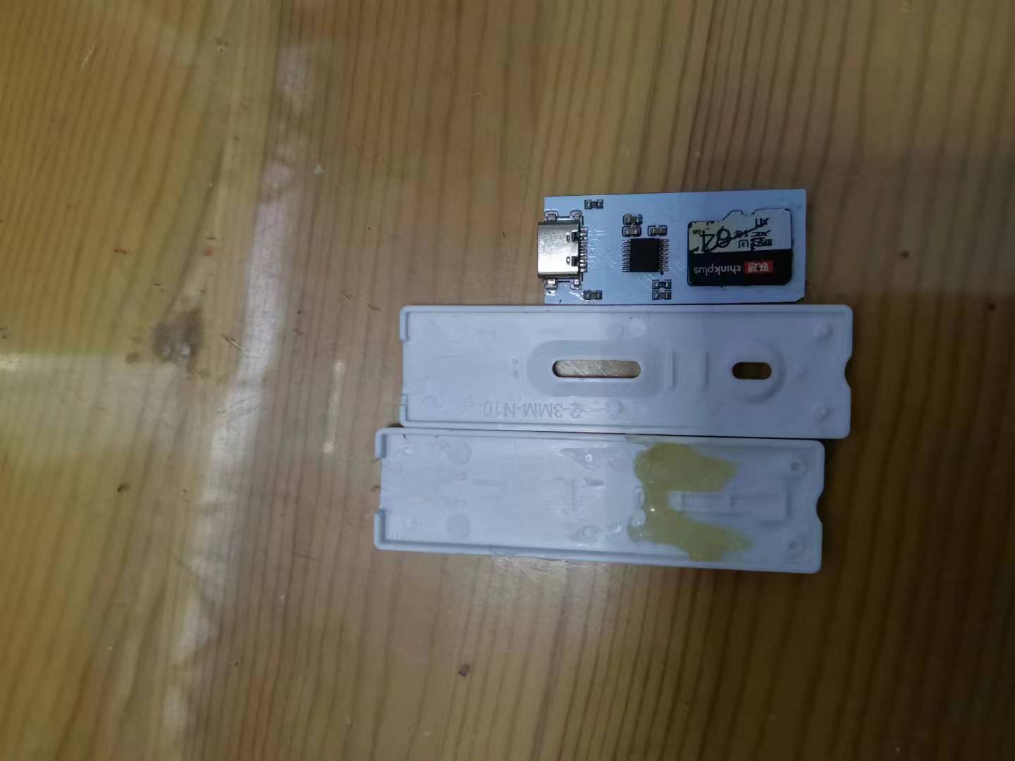 Place the board like this, don't install it backwards. The board should be 1mm or 0.8mm thick, but the Type-C port should be 1.6mm to better utilize space.
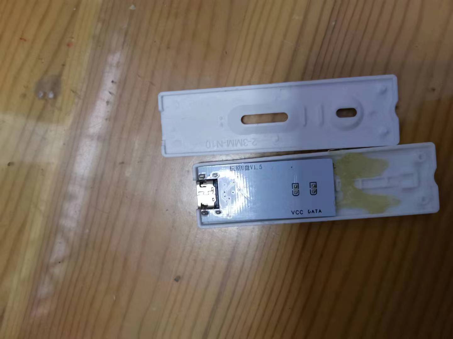


 京公网安备 11010802033920号

 LC3564CT


