
The "Warm Winter Creation" activity requirements:
When I first saw this activity, my immediate reaction wasn't to see the requirements, but to the coupons on the cover. Four types of free coupons (not really), it was practically a no-brainer to participate. After registering, I looked at the requirements—a warm and festive Chinese New Year/Christmas theme.
My first thought upon registering was definitely the nearest holiday—Christmas. I initially thought of a Christmas tree, but couldn't figure out how to make it three-dimensional. Some of my previous single-sided designs looked too flimsy, and since I'd already made them, I couldn't copy them, so I put them aside for a while. Because I often get free materials, but the quantity is very limited—only one or two, basically enough for two samples—I've always had the idea of using all five boards simultaneously, but I haven't had a clue how. Sure enough, one day when I opened the registration form and filled out the link, I saw He Diangong's idea. Sure enough, there was a Christmas tree! He used five free boards to create a three-dimensional Christmas tree—a fantastic idea. Here's his project link—a mini Christmas tree based on the WS2812.
The special nature of being able to get free materials also led me to be too frugal, foreshadowing the poor lighting effects in the final product. Of course, the main point here is that the Christmas theme didn't work for me. So, for me, the remaining four words basically fall into the category of New Year, which is related to red. Then, based on the fact that the maximum freebie size of the board is 100*100, I thought of a square "福" (Fu, meaning good fortune) character, since it can be rotated into a rhombus shape, and the through hole for GND can be used to hang a rope, which is simply ingenious! However, I then looked at the rules and found that it does not allow simple lighting (at that time, I hadn't even figured out how to light it). To hang the "福" character, it doesn't need to be connected to batteries, so it must be battery-powered, and there should be charging and discharging interfaces, and I need to consider adding a microcontroller to avoid it being just simple lighting. Due to my limited skills, I shelved it.
Inspiration came
when I was at a loss for the design of the four types of coupons, the Year of the Dragon mascot Long Chenchen became popular (lol), sparking a lot of discussion. Even my favorite five-star general, General MacArthur, commented on it - a large-scale documentary "The Year of the Dragon Mascot". I was thinking about whether there were any elements related to the Year of the Dragon, and then I came across the "[Hupu Sharp Review] Annual Outstanding Year of the Dragon Mascot Selection", and the first place was "Dragon Hero"! I spotted a familiar figure—Shendu. I'd just rewatched Jackie Chan Adventures with a premium membership, and the inspiration for the design came from the abstract concept of the talisman or Shendu's disc shape. Initially, I considered using a Shendu statue
for the pattern and shape
, but the size wasn't large enough to represent the talisman slot. Then, I happened to be watching episode 11, Shendu's resurrection, and saw the distinctive Shendu symbol. I decided to use this as the color screen printing pattern, and the shape also used the talisman's form from the anime. I
embarrassingly miscalculated the octagonal parameters when I started designing. Looking at the talisman, I thought a regular octagon should be obtained by subtracting the same length from both sides of the existing square. However, no matter how I subtracted, I couldn't get a regular octagon. After subtracting, it felt strange. I happened to have seen a project with an octagon before, and after looking at it, I realized how absurd my calculation was. So, I directly copied the shape, and also copied the Tai Chi symbol. Thus, the pattern and shape of the entire board were temporarily resolved. For the
outer shell and panel,
I chose LEDs for the top and bottom shells respectively. Although the 6060 and 9000R models weren't marked as transparent on the parameter panel, the small LEDs actually allowed light to pass through the casing. Considering the light-blocking effect, a black material like PLA
was chosen, and a frosted thin-film panel was opted for. The intention was to avoid using any screws that would compromise the overall shape (although the bottom casing was eventually damaged). In fact, the frosted finish has minimal effect on preventing light transmission. Strong light blocking was prioritized.
Based on the PCB shape, a simple casing model was generated using LCSC EDA, but it was very basic, with many things difficult to adjust. This forced the use of other modeling software. It's worth mentioning that LCSC EDA's board frame layer cannot be parametrically modeled; everything had to be done manually. Some shapes were extremely difficult to design. Then, only Fusion 360 VIP could export to DXF format, rendering the design useless. So, I had to redraw it in CATIA and export it again, then use Fusion 360 to further refine the internal structure of the casing.
Since this was the first time trying both the panel and the casing, there were many mistakes in the printing materials and various selection tests, resulting in an unsatisfactory final product. However, the initial intention of the event was probably to encourage everyone to try out new functions
and modify
the circuit design. I considered dual op-amp breathing lights, flowing lights, etc., but I wanted the lighting effect to gradually brighten, emitting red light in the eyes area, which matched the original animation. Therefore, I chose touch stepless dimming. I originally planned to use a microcontroller, but due to time constraints, I ended up using a pure hardware circuit. At this point, I made an old mistake again: I used a basic LED light that I already had on hand, which is a big no-no for a work that requires lighting effects. Fortunately, I also chose a full red light, otherwise it would have been completely unwatchable.
The original bottom layer of the pattern was a Tai Chi diagram, which, combined with the two touch springs, perfectly preserved the aesthetics of the pattern itself. However, since I had never tried color screen printing before, I was unsure if the circuitry would be exposed, and the integrity of the components on the back had already been compromised. So, I simply used the Jackie Chan Adventures icon, which matches the original animation. I added an LED on the back as an indicator light, and placed the protruding part of the touch spring in the dark part of the top layer pattern to maximize the integrity of the top layer pattern.
There are several design options for the housing and panel, but due to time constraints and unfamiliarity with these new functions and processes, the safest option was chosen: placing it internally, with the panel providing light shielding and the housing having slots for light transmission. Various tolerances and the fit between the upper and lower housings were also considered (a long section was cut off by a bug), so I'll leave it at that. The schematic design is
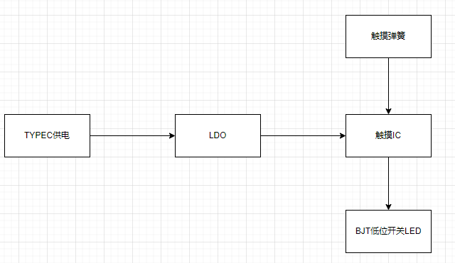
a very simple touch chip design, almost an example. The actual design is below, and the layout references a touch-sensitive stepless dimming snowflake LED. I came across this project when I found the schematic too ugly after completing my design. Fan-out netting is a great feature; the experts really know how to do it.
The PCB design
layout
idea was to place all components except the lighting on the bottom layer to ensure a neat and complete look with the colored silkscreen on the top layer. However, due to habit, the TYPE-C port was placed on top, and I didn't realize that the connector isn't long and wouldn't protrude from the top layer when reversed. If the solder amount is controlled well, the top layer can be very flat. Although it doesn't look out of place, I strongly recommend placing the TYPE-C port on the bottom layer as well.
The lack of any testability design on this board is a major mistake. The original idea was that there were no technical or soldering difficulties (where did they get the nerve?). The TYPE-C interface, in particular, was a 6-pin power-only version, and the fact that it wasn't placed on the back was also a flaw. This made testing the TYPE-C extremely difficult due to poor soldering. Multimeter probes had to be inserted on both sides simultaneously, and there were no through-holes. Those replicating this board must learn from this lesson and make the necessary changes (is this even worth replicating? XD). When routing the traces,
pay
close attention to ensuring that the input and output signal lines of the critical touch chip are not interfered with by other traces. Consider copper shielding, and keep input signal lines as short and thin as possible, around 5mil is recommended. You can refer to JLCPCB's PCB design specifications for more information. The
software specifications
require no software code; it only needs power to operate. The physical
product demonstration explains that
the TYPE-C socket on the casing was initially enlarged to include the plastic parts, considering potential variations in insertion and removal lengths. However, actual testing revealed that this enlargement was unnecessary. Users can refer to their casing wall thickness to determine if a larger opening is needed at the socket. The TYPE-C engineering drawings do not specify insertion depth, so you can refer to my TYPE-C cable; it should just exceed the wall thickness after insertion.

Note:
Capacitor values are recommended between 1nF and 10uF, with a default of 47nF. During the functional testing phase, the capacitor value's impact on sensitivity is not significant; it lights up even with a manual press. Adjustments can be made gradually after using the mold.
Soldering TYPE-C is very important!!! When using a soldering iron, solder the terminals first, then the socket. When using a hot air gun, pay attention to the temperature to avoid melting the solder core. Use plenty of flux.
Other attachments are uploaded.


 京公网安备 11010802033920号

 1M1016-050-3319-020.0-03-CB-22-0


