The Funina Light Ripple NFC card features color silkscreen printing and supports QQ Music activation.
qqmusic://qq.com/ui/openUrl?p={"url":"http://985.so/wbzhb","action":"play"}.
Other display images are also available.
A simple amateur radio transmitter that supports AM/SSB/DSB and various digital modes.
Disclaimer: The use of radio transmitting equipment must comply with relevant national laws and policies. Unauthorized use is prohibited. The author assumes no responsibility for any adverse consequences resulting from unauthorized radio transmission operations based on the content of this article without approval from relevant departments.
The transmitter described in this article is the author's first complete amateur radio transmitter, conceived entirely from basic electronic technology theory. It possesses the following characteristics:
1. It can operate on a 3.5MHz 80m amateur radio frequency, enabling communication in various modes including AM, SSB, DSB, WSPR, FT8, JT65, and PSK31. It can output approximately 0.5W of power under 5V supply.
2. It does not use complex frequency synthesis techniques such as PLL phase-locked loop frequency synthesizers or DDS direct digital synthesis. Instead, it uses only a 3.58MHz passive crystal oscillator as the frequency source, and achieves audio signal modulation in USB or LSB mode to any frequency point within a 48kHz range centered at 3.58MHz through software methods.
3. Theoretically, it meets the spurious emission requirements for shortwave amateur radio stations in GB/T 32658-2016 "Amateur Radio Equipment RF Technical Requirements and Test Methods," with second harmonic suppression no worse than 43dBc and third harmonic suppression no worse than 60dBc.
The local oscillator is a simple crystal oscillator based on an inverter, which outputs a 3.58MHz square wave signal, which is fed into the gate of MOS transistor Q4, which acts as the modulator.
After the input audio signal passes through a capacitor to remove the DC component and an inductor to suppress the RF component, it is input to the modulator. The amplitude of the modulator's output 3.58MHz signal changes with the amplitude of the input audio signal, thus achieving AM modulation. It is conceivable that if crystal oscillator U9 is soldered into the circuit, it will filter out the 3.58MHz carrier signal, achieving DSB modulation; however, this has not been actually tested. The modulator requires a certain driving capability for the audio input. If insufficient output RF power is found, an audio amplifier may need to be added before the audio signal input.
The modulated signal, after passing through a Class AB power amplifier with Q1-Q3 connected, produces approximately 0.5W of output power under a 5V supply. Further increasing the supply voltage yields higher output power.
To reduce spurious signals, the amplifier signal is passed through a seventh-order Chebyshev low-pass filter to remove higher harmonics.
The crystal oscillator has a frequency of 3.58MHz. How can it transmit WSPR signals on a common frequency (3.570MHz, typically 3.5686MHz for USB + 1500Hz audio)? First, the 1.5kHz audio signal generated by the WSJT-X software is mixed with an 11.5kHz signal. The upper sideband frequency is 13kHz, and the lower sideband frequency is 1.5kHz. The lower sideband is used, while the upper sideband is suppressed. The mixing result is sent to the modulator, and the resulting lower sideband is 3.570MHz. During this process, the signal undergoes two sideband flips, resulting in the upper sideband signal.
The above process is implemented using GNURadio. First, the WJST-X output audio transmitted via Line 1 of the Virtual Audio Cable software undergoes a Hilbert transform to obtain a complex signal with only positive frequency components. Then, its conjugate is taken to obtain a signal with only negative frequency components. This signal is multiplied by a 10kHz complex sine wave to obtain the desired modulated lower sideband signal, which is then output through the computer's sound card. A similar approach can be used to transmit single-sideband signals at other frequency points within the 3.58MHz±24kHz range, which will not be elaborated upon here.
1. Project Introduction:
Based on the official tutorial, learn and replicate the intelligent car based on LCSC's Liangshanpai model.
Problem Analysis
: 1.1. Car Function Introduction:
The Liangshanpai intelligent car is equipped with two LED lights at the front, one on each side, which can be used to simulate the headlight status when driving or passing other vehicles;
the Liangshanpai intelligent car has two independent buttons, KEYS and KEYM, which can be used to start the car and switch between driving modes;
the Liangshanpai intelligent car is equipped with a buzzer, which can be used to sound an alarm when encountering obstacles, and its output frequency can also be changed using a timer to play music;
the Liangshanpai intelligent car is equipped with four motor drives and four N20 motors, enabling PWM output and speed control;
the Liangshanpai intelligent car is equipped with five-channel infrared tracking, which can be used to follow black lines. Learn the use of comparator circuits and implement...
The Liangshanpai Smart Car features a tracking function; it is equipped with an HCSR04 ultrasonic module interface circuit, which allows for ultrasonic obstacle avoidance by learning the module's principles and underlying driver code;
the Liangshanpai Smart Car utilizes the ADC function on the development board to detect the car's battery level, facilitating timely charging;
it provides an HC-05 Bluetooth module interface circuit, enabling wireless remote control of the car via a mobile Bluetooth app;
it offers a camera module interface circuit, which can be used to learn about camera recognition;
and it provides a 2.4G wireless module interface circuit, allowing for remote control of the car.
1.2. Application Scenarios of the Car
This tutorial is suitable for electronics enthusiasts and beginners to learn basic projects;
it is suitable for embedded courses, using a smart car in conjunction with the LCSC Liangshanpai development board to integrate embedded courses;
it is suitable for university course design and graduation project reference cases, allowing students to complete smart car projects with specific functions according to course design requirements using the LCSC Liangshanpai core board;
it is suitable for students and related personnel to learn about related smart car competitions;
2. Overall Design Scheme The overall design scheme
of the Liangshanpai smart car system framework diagram is shown in Figure 2-1. The power supply circuit uses two 7.4V lithium batteries to power the system, and the voltage is stepped down to 5V by a step-down chip to power the microcontroller system. The LCSC Liangshanpai core board is connected to the LED lights, button circuit, obstacle avoidance circuit, line tracking circuit, ADC voltage acquisition circuit, Bluetooth remote control circuit (wireless remote control function), buzzer, and motor drive circuit on the smart car expansion board.
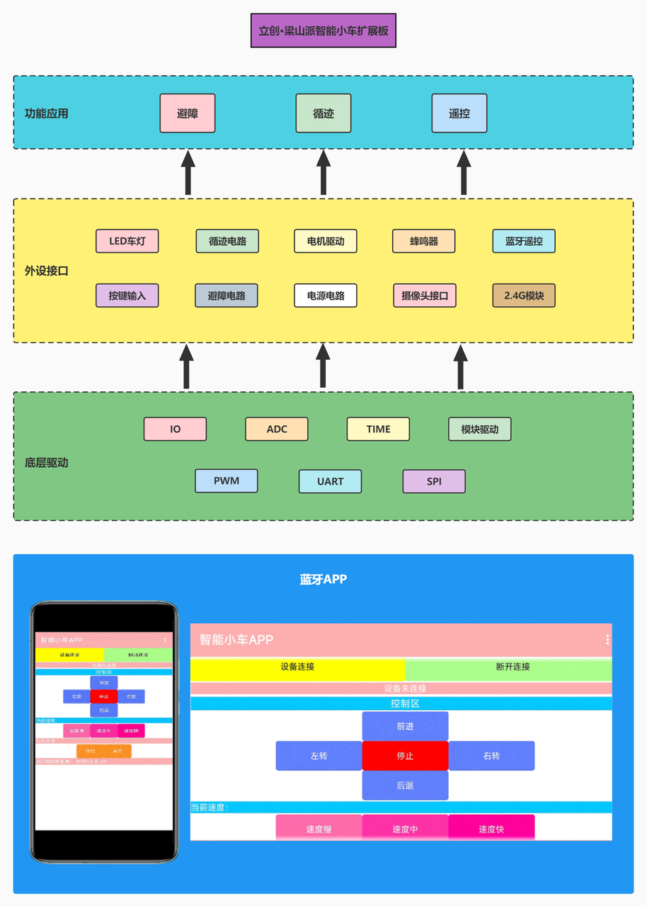
Figure 2-1 Overall System Framework Diagram
3. Circuit Design
3.1 Power Input Circuit
3.1.1 Power Design Requirements
We analyzed the power supply circuit of the intelligent car system. By consulting the chip manual and the schematic diagram of the LCSC Liangshanpai core board, we learned that the maximum supply voltage of the motor drive chip RZ7899 does not exceed 25V, the LCSC Liangshanpai core board is powered by 3.3V (compatible with 5V), the ultrasonic module is powered by 5V, and the other peripheral modules are all powered by 3.3V. Based on this requirement, we can start selecting the power supply. Here, I chose a 7.4V rechargeable lithium battery. You don't have to follow my example; choose according to your needs.
3.1.2 Intelligent Car Power Supply Schematic Diagram
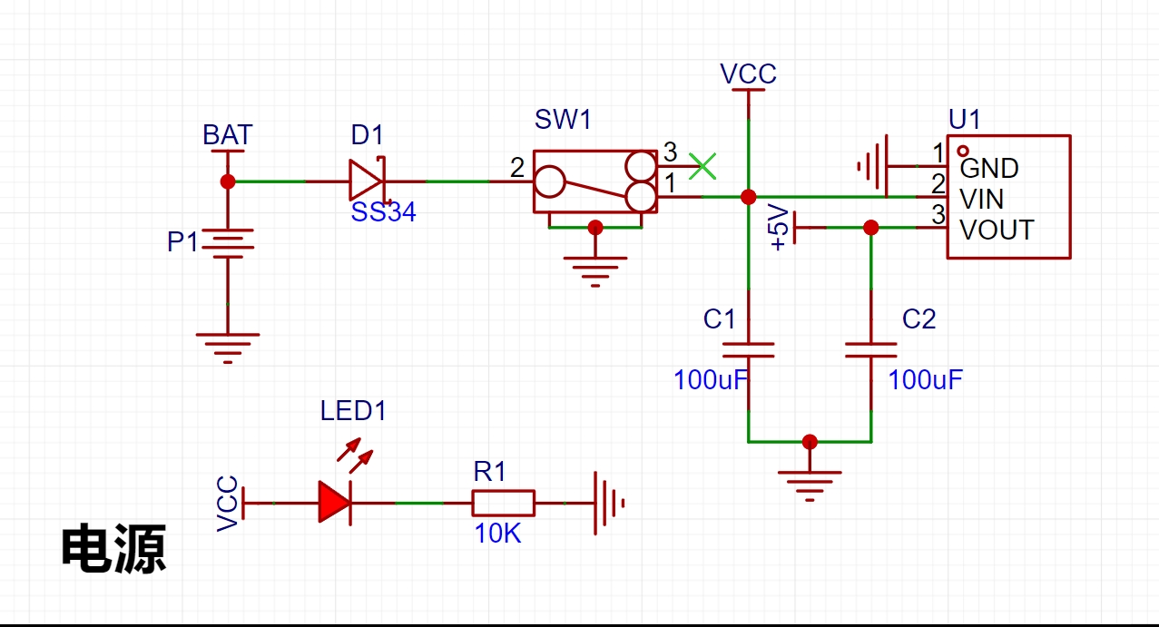
Figure 3-1 Power Circuit Schematic Diagram
3.1.3 Power Circuit Design Analysis
The power input interface P3 is a battery holder. Two 3.7V lithium batteries are connected through the battery holder to power the car. After the power supply enters, it passes through an HE6250MPR step-down chip. This chip has a maximum input voltage of 15V and can output a fixed 5V voltage to power the microcontroller and peripheral devices. The motor driver chip is directly powered by a 7.4V battery. D1 is a Schottky diode, model SS43, used to prevent reverse polarity connection of the power input, providing protection. LED1 is the power indicator light; it illuminates when the power switch SW1 is turned on, indicating system power is supplied. C1 and C2 are 10uF capacitors, primarily used to buffer the potentially large current flow during power-on.
3.2 Minimum System Circuit for Microcontroller
Undoubtedly, we use the LCSC Liangshanpai core board as our minimum system board. The LCSC Liangshanpai core board uses the GD32F470 main control chip, which has extremely high computing performance, with a maximum processor frequency of 200MHz, and provides a complete DSP instruction set, parallel computing capabilities, and a dedicated floating-point unit (FPU) to meet advanced computing needs. Specific information and details about the LCSC Liangshanpai core board will not be discussed here; please refer to the LCSC development board official website for more information.
3.3 Motor Drive Circuit
3.3.1 Motor Drive Circuit Schematic Diagram

Figure 3-2 Motor Drive Circuit Schematic Diagram
3.3.2 Motor Drive Circuit Design Analysis
First, we all know that the current of the microcontroller's I/O ports is very limited. If the motor is directly connected to the microcontroller's I/O ports, it will not be able to drive the motor properly. Therefore, we must use a motor drive chip to drive our motor assembly. Here, I choose the RZ7899 motor drive chip. The RZ7899 is a DC bidirectional motor drive circuit suitable for automatic valve motor drives, electromagnetic door lock drives, etc. This circuit features excellent anti-interference capabilities, minimal standby current, and low output resistance. It also has a built-in diode to release reverse inrush current from inductive loads.
It controls the motor's forward, reverse, and braking functions through two logic input terminals, BI and FI. By connecting BI and FI to the microcontroller's I/O ports and changing the microcontroller's I/O port level, the output pin level of the chip's control terminal can be altered, allowing for forward/reverse rotation, stopping, and braking control of the motor. The control principle is very simple, making it convenient to use and capable of meeting the high current requirements of DC motors.
During code debugging, the pin function table and input/output truth table below can be referenced. By connecting the BI and FI pins to the microcontroller's timer channel pins, the microcontroller's timer PWM output function can be used to control the motor speed, thereby changing the speed of the intelligent vehicle.
Chip features include:
minimal standby current (less than 2uA); wide operating voltage range (3.0V~25V);
emergency stop function; and overheat protection.

Figure 3-4 Ultrasonic Module Interface Diagram
3.5.2 Obstacle Avoidance Circuit Design Analysis
The principle of ultrasonic ranging is that the ultrasonic transmitter emits ultrasonic waves and starts timing at the same time. The ultrasonic waves propagate in the air. When they encounter an obstacle, they will send a signal back to the ultrasonic receiver. The ultrasonic receiver stops timing immediately after receiving the signal. At this time, there will be a time t. The speed of ultrasonic waves in the air is 340m/s. The distance to be measured can be calculated by the formula s=340 xt / 200.
HC-SR04 Ultrasonic Ranging Module Working Principle:
Operating voltage: DC 5V;
Ranging is triggered by I/O port. The microcontroller sends a high-level signal of at least 10us to the Trig pin of the ultrasonic module to trigger its operation.
The module's transmitting probe automatically sends eight 40KHz square wave signals and automatically detects whether a signal is returned.
If a signal is returned, a high-level signal is output through the I/O port of the microcontroller connected to the Echo pin. The duration of the high-level signal is the time from ultrasonic transmission to return.
Based on the speed of sound in air being 340 meters per second, the measured distance can be calculated.
It has overcurrent protection, current clamping, and short-circuit protection functions. Package size: SOP8.
3.4 Tracking Circuit
3.4.1 Tracking Circuit Schematic Diagram
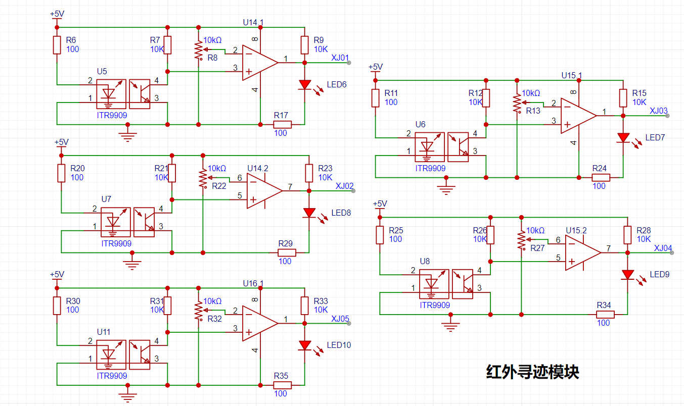
Figure 3-3 Tracking Circuit Schematic Diagram
3.4.2 Tracking Circuit Design Analysis
The design of the tracking circuit utilizes the principle that infrared light reflects differently when encountering ground of different colors. The tracking circuit uses an LM393 voltage comparator and an ITR9909 infrared transistor. The ITR9909 integrates an infrared emitter and receiver. The tracking principle involves connecting pin 1 of the voltage comparator to a microcontroller pin, configuring the I/O to input mode. When pin 1 of the voltage comparator outputs a high level, it indicates that the infrared light is absorbed, a black line is detected, LED6 lights up, and the microcontroller I/O reads the high level.
The principle of infrared tracking is based on the reflection of infrared light at different colors. Detecting
a black line involves the infrared emitter emitting light to the ground; when the infrared light encounters a white ground, it is reflected, and the infrared receiver receives the reflected light. After passing through the voltage comparator, the output is low.
Detecting a black line involves the infrared emitter emitting light to the ground; when the infrared light encounters a black ground, it is absorbed, and the infrared receiver does not receive the reflected light. After passing through the voltage comparator, the output is high.
3.5 Obstacle Avoidance Circuit
3.5.1 Obstacle Avoidance Circuit Schematic Diagram
The obstacle avoidance circuit uses an ultrasonic HC-SR04 module. The type of this module can be selected and purchased independently. A physical diagram is shown below.

Below is the ultrasonic module interface on the expansion board of the intelligent car.
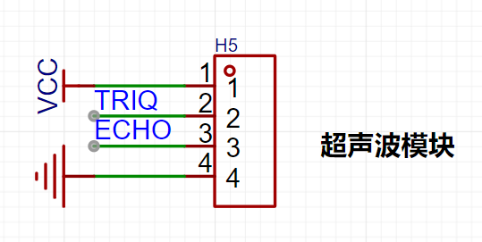
Figure 3-4 Ultrasonic Module Interface Diagram
3.5.2 Obstacle Avoidance Circuit Design Analysis
The principle of ultrasonic ranging is that the ultrasonic transmitter emits ultrasonic waves and starts timing at the same time. The ultrasonic waves propagate in the air. When they encounter an obstacle, they will send a signal back to the ultrasonic receiver. The ultrasonic receiver stops timing immediately after receiving the signal. At this time, there will be a time t. The speed of ultrasonic waves in the air is 340m/s. The distance to be measured can be calculated using the formula s=340 xt / 200.
Working principle of HC-SR04 ultrasonic ranging module
Working voltage: DC 5V;
The ranging is triggered by I/O port. The microcontroller sends a high-level signal of at least 10us to the Trig pin of the ultrasonic module to trigger the ultrasonic module to work;
The transmitting probe of the module will automatically send 8 40KHz square wave signals and automatically detect whether there is a signal return;
If there is a signal return, the microcontroller's I/O port is connected to the Echo pin to output a high level. The duration of the high level is the time from the ultrasonic wave to the return;
According to the speed of sound in the air, which is 340 meters/second, the measured distance can be calculated;

Figure 3-5 Working timing diagram of ultrasonic HC-SR04 module
3.6 Other circuits
3.6.1 LED car light and button circuit
(1) One end of the LED light is connected to the microcontroller's IO port. The LED light is controlled by the high and low levels of the microcontroller's IO. Two driving methods are designed here. The circuit of the LED car light is lit at a low level, and the circuit of the button indicator light is lit at a high level. The resistance can be calculated by combining the required brightness of the light and Ohm's law. For example, if the indicator light of the button does not need to be too bright, the resistance should be 1KΩ, which is larger. If the LED car light needs to be brighter, the resistance should be 100Ω, which is smaller.
(2) The circuit design principle of the independent button here is to connect one end of the button to the microcontroller IO port and the other end to ground. When the button is pressed, a low level is read; when the button is released, a high level is read. Note that the IO port needs to be configured as a pull-up input. Of course, you can also add a pull-up resistor to pull the level of the IO port high, so that it does not need to be configured as a pull-up input.
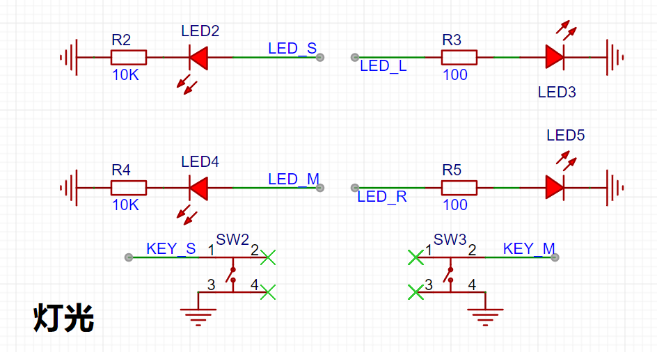
Figure 3-6 LED light circuit schematic diagram
3.6.2 Buzzer and ADC voltage acquisition circuit
(1) Buzzer circuit: The buzzer used here is an active buzzer. The active buzzer has its own oscillation source. As long as it is powered on, it will make a sound. The circuit design principle here is to use a PNP type transistor as a switch. By adjusting the high and low levels of the microcontroller IO port, the buzzer can be controlled. The reason for using a transistor is that we all know that the current driving capability of a microcontroller is relatively small, and it cannot work properly if it directly drives the device. Therefore, the emitter of the transistor is used to guide the current into the collector, instead of directly applying the microcontroller's I/O port to the buzzer.
When the I/O port outputs a high level, the emitter voltage is not much greater than the base voltage, the transistor is not conducting and is in the cutoff state, so the buzzer does not make a sound;
when the I/O port outputs a low level, the emitter voltage is much greater than the base voltage, the transistor conducts, the current flows from the emitter into the collector, and the buzzer makes a sound.

Figure 3-7 Buzzer circuit schematic
(2) ADC voltage acquisition circuit: First, before using the ADC, we need to know its bit number, i.e., its precision. We can find out from the datasheet that our ADC is 12-bit, and through calculation, we know that the precision is 2^12-1, which equals 4095. This means that the precision range that the ADC can represent is 0~4095.

Figure 3-8 Schematic diagram of ADC voltage acquisition circuit
4. Schematic diagram and PCB design
4.1.1 Overall schematic diagram design
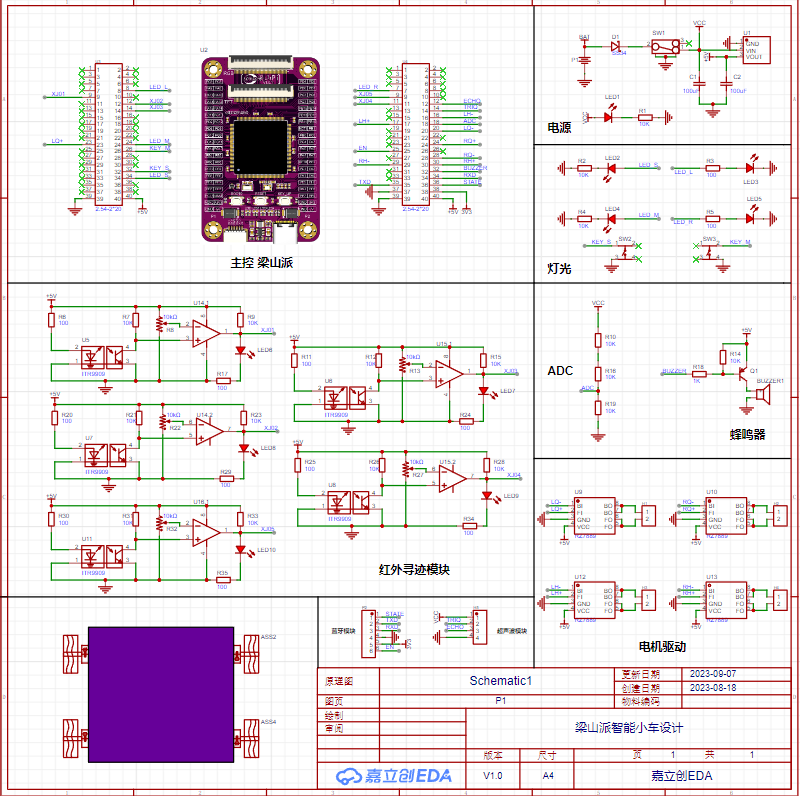
Figure 4-1 Overall schematic diagram
4.1.2 Schematic diagram design precautions
(1) When selecting components, prioritize components from the basic library and those with more inventory;
(2) Keep the shipping warehouses of different components consistent as much as possible;
(3) Components with different packages have different sizes. It is recommended that beginners or those with weak soldering skills choose through-hole packages or 0805 packages. Of course, you can also directly use SMT surface mount technology;
(4) Minimize the types of components. For example, if an 800Ω resistor and a 1000Ω resistor can be substituted for each other without affecting the circuit, choose one of them;
(5) After the schematic diagram is designed, it should be organized. Each module should be enclosed in a grid. This will make the overall structure of the schematic diagram clearer and easier to read;
4.2 PCB design
4.2.1 PCB design
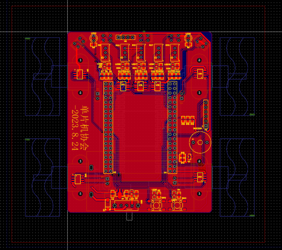
Figure 4-2-1 PCB diagram
4.2.2 Car PCB outline design

Figure 4-2-2 Car 3D diagram
4.2.3 PCB Design Considerations
(1) Power and signal traces should be laid out strictly according to the schematic diagram, following the direction of signal current flow. Even if they are all connected without errors, the order should be considered. They should go through A first, then B, and finally C. They should not go directly from A to C to B. This is especially important for beginners.
(2) Avoid right angles when routing. Generally, take a 45-degree route or an arc. In high-frequency circuits, do not take right angles or acute angles when turning to prevent signal reflection when the high-frequency signal turns.
(3) The width of the power line should be wider than the signal line. GND is generally done by copper pouring.
(4) Under normal circumstances, the width of the conductor should not be less than 10mil. Generally, the power line is set to a width of 25mil or more.
5. Software Design
5.0 Code Standards
Have you ever encountered a situation where you feel that you can hardly understand your own code or even forget the programming logic when you read it again after a long time? When you send your code to others, it is often criticized? You name variables a, b, c directly, and then you are confused when you look at it again?
Many of us have made some of the mistakes mentioned above, highlighting the crucial role of coding standards in software design. Developing good coding habits helps avoid these errors, allowing you to write code that flows smoothly and is easy to read. Below, I will discuss some coding standards for your reference.
Modular programming: Separate modules into independent .c and .h files for quick code portability.
Add appropriate comments: Add necessary comments to header files, functions, variables, and control logic.
Variable and function naming conventions: Variable and function names should be self-explanatory.
Maintain standardized code formatting: Indent where necessary and add parentheses where required.
5.1 Partial Code
5.1.1 Tracking Code
track.h
1) The track.h header file mainly contains referenced header files, macro definitions, and function declarations.
2) To avoid redefining header files, conditional compilation is used: #ifndef xx: if xx is not defined; #define xx: then define xx; #endif: end.
#ifndef _TRACK_H #define _TRACK_H #include "gd32f4xx.h" #include "systick.h" #define XJ01_RCU RCU_GPIOA // Clock for GPIOA #define PORT_XJ01 GPIOA // Port for GPIOA #define XJ01_PIN GPIO_PIN_15 // Pin for GPIOA #define XJ02_RCU RCU_GPIOC // Clock for GPIOC #define PORT_XJ02 GPIOC // Port for GPIOC #define XJ02_PIN GPIO_PIN_10 // Pin for GPIOC #define XJ03_RCU RCU_GPIOC // Clock for GPIOC #define PORT_XJ03 GPIOC // Port for GPIOC #define XJ03_PIN GPIO_PIN_12 // Pin for GPIOC #define XJ04_RCU RCU_GPIOB // Clock for GPIOB #define PORT_XJ04 GPIOB // Port for GPIOB #define XJ04_PIN GPIO_PIN_13 // Pin for GPIOB #define XJ05_RCU RCU_GPIOB // Clock for GPIOB #define PORT_XJ05 GPIOB // Port for GPIOB #define XJ05_PIN GPIO_PIN_15 // Pin for GPIOB #define No_Black_Line_Found 0 // No black line detected #define Black_Line_Found 1 // Black line detected void track_gpio_config(void); // Tracking GPIO pin configuration void Black_Line_Detection(void); // Black line detection function #endif /* TRACK_H */
track.c
#include "track.h" FlagStatus XJ01 = RESET; FlagStatus XJ02 = RESET; FlagStatus XJ03 = RESET; FlagStatus XJ04 = RESET; FlagStatus XJ05 = RESET; /******* Function Name: track_gpio_config Function: Track GPIO pin configuration parameters: None Return Value: None **********/ void track_gpio_config(void) { /* Enable clock / rcu_periph_clock_enable(XJ01_RCU); / Configure as input mode pull-up mode / gpio_mode_set(PORT_XJ01,GPIO_MODE_INPUT,GPIO_PUPD_PULLUP,XJ01_PIN); / Enable clock / rcu_periph_clock_enable(XJ02_RCU); / Configure as input mode pull-up mode / `gpio_mode_set(PORT_XJ02,GPIO_MODE_INPUT,GPIO_PUPD_PULLUP,XJ02_PIN);` / Enable clock / `rcu_periph_clock_enable(XJ03_RCU);` / Configure as input pull-up mode / `gpio_mode_set(PORT_XJ03,GPIO_MODE_INPUT,GPIO_PUPD_PULLUP,XJ03_PIN);` / Enable clock / `rcu_periph_clock_enable(XJ04_RCU);` / Configure as input pull-up mode / `gpio_mode_set(PORT_XJ04,GPIO_MODE_INPUT,GPIO_PUPD_PULLUP,XJ04_PIN);` / Enable clock / `rcu_periph_clock_enable(XJ05_RCU);` / Configure as input pull-up mode */ gpio_mode_set(PORT_XJ05,GPIO_MODE_INPUT,GPIO_PUPD_PULLUP,XJ05_PIN); } /******* Function Name: Black_Line_Detection Function: Black line detection function Parameters: None Return Value: None **********/ void Black_Line_Detection(void) { XJ01 = gpio_input_bit_get(PORT_XJ01,XJ01_PIN); XJ02 = gpio_input_bit_get(PORT_XJ02,XJ02_PIN); XJ03 = gpio_input_bit_get(PORT_XJ03,XJ03_PIN); XJ04 = gpio_input_bit_get(PORT_XJ04,XJ04_PIN); XJ05 = gpio_input_bit_get(PORT_XJ05,XJ05_PIN); }
main.c
#include "main.h" #include "stdlib.h" #include "string.h" #include "bsp_pwm.h" #include "motor.h" #include "track.h" #include "bsp_led.h" #include "bsp_key.h" #include "bsp_beep.h" uint16_t No_Black_Line_TimeCount = 0 ; // No black line found time uint8_t LongTime_No_Black_Line_Flag = 0 ; // Flag indicating no black line found for a long time extern FlagStatus XJ01; extern FlagStatus XJ02; extern FlagStatus XJ03; extern FlagStatus XJ04; extern FlagStatus XJ05; /******* Function Name: main Functionality: Main function parameters: None Return value: None********/ int main(void) { `nvic_priority_group_set(NVIC_PRIGROUP_PRE2_SUB2);` // Priority grouping; `systick_config();` // Tick timer initialization; `pwm1_config(200, 100);` // Timer 1 PWM configuration: PWM output frequency 10kHz; `pwm2_config(200, ...`100); // Timer 2 PWM configuration PWM output frequency 10KHZ Speed adjustment 0-100 motor_gpio_config(); // Motor drive pin initialization track_gpio_config(); // Tracking gpio pin configuration beep_gpio_config(); led_gpio_config(); key_gpio_config(); // Stop the engine car_stop(Flameout_Stop); // Turn off the headlights and buzzer beep_off(); led_l_off(); led_r_off(); LEDS=0; LEDM=0; while(1){ Black_Line_Detection();// Black line detection function if(XJ01==No_Black_Line_Found && XJ02==No_Black_Line_Found && XJ03==Black_Line_Found && XJ04==No_Black_Line_Found && XJ05==No_Black_Line_Found)//3 Black line detected in the middle 00100 { car_front(87); //Forward} if(XJ01==No_Black_Line_Found && XJ02==Black_Line_Found && XJ03==Black_Line_Found && XJ04==Black_Line_Found && XJ05==No_Black_Line_Found)//2 3 Black line detected in the middle 00100 { car_front(87); //Forward} if(XJ01==No_Black_Line_Found && XJ02==Black_Line_Found && XJ03==Black_Line_Found && XJ04==No_Black_Line_Found && XJ05==No_Black_Line_Found)//2 3 Black line detected (smaller to the right) 01100 { motor_LQ_front(40); motor_LH_front(40); motor_RQ_front(87); motor_RH_front(87); } if(XJ01==No_Black_Line_Found && XJ02==Black_Line_Found && XJ03==No_Black_Line_Found && XJ04==No_Black_Line_Found && XJ05==No_Black_Line_Found)//2 Black line detected (right bias) 01000 { motor_LQ_front(30); motor_LH_front(30); motor_RQ_front(87); motor_RH_front(87); } if(XJ01==No_Black_Line_Found && XJ02==No_Black_Line_Found && XJ03==Black_Line_Found && XJ04==Black_Line_Found && XJ05==No_Black_Line_Found)//4 3 Black line detected (left bias) 00110 { motor_LQ_front(87); motor_LH_front(87); motor_RQ_front(40); motor_RH_front(40); } if(XJ01==No_Black_Line_Found && XJ02==No_Black_Line_Found && XJ03==No_Black_Line_Found && XJ05==No_Black_Line_Found)//4 black line detected (larger to the left) { motor_LQ_front(87); motor_LH_front(87); motor_RQ_front(30); motor_RH_front(30); } if(XJ01==Black_Line_Found && && XJ04==No_Black_Line_Found && XJ05==No_Black_Line_Found)//1 2. Black line detected (left turn) { motor_LQ_back(55); motor_LH_back(55); motor_RQ_front(87); motor_RH_front(87); } if(XJ01==Black_Line_Found && XJ02==No_Black_Line_Found && XJ03==No_Black_Line_Found && XJ04==No_Black_Line_Found && XJ05==No_Black_Line_Found)//1. Black line detected (left turn) { motor_LQ_back(45); motor_LH_back(45); motor_RQ_front(87); motor_RH_front(87); } if(XJ01==Black_Line_Found && XJ02==Black_Line_Found && XJ03==Black_Line_Found && XJ04==No_Black_Line_Found && XJ05==No_Black_Line_Found)//1 2 3 Black line detected (left turn) { motor_LQ_back(35); motor_LH_back(35); motor_RQ_front(87); motor_RH_front(87); } if(XJ01==No_Black_Line_Found && XJ02==No_Black_Line_Found && XJ03==No_Black_Line_Found && XJ04==Black_Line_Found && XJ05==Black_Line_Found)//4 5 Black line detected (right turn) { motor_LQ_front(87); motor_LH_front(87); motor_RQ_back(55); motor_RH_back(55); } if(XJ01==No_Black_Line_Found && XJ02==No_Black_Line_Found &&XJ03==No_Black_Line_Found && XJ04==No_Black_Line_Found && XJ05==Black_Line_Found)//5 Black line detected (right turn) { motor_LQ_front(87); motor_LH_front(87); motor_RQ_back(45); motor_RH_back(45); } if(XJ01==No_Black_Line_Found && XJ02==No_Black_Line_Found && XJ03==Black_Line_Found && XJ04==Black_Line_Found && XJ05==Black_Line_Found)//3 4 5 Black line detected (right turn) { motor_LQ_front(87); motor_LH_front(87); motor_RQ_back(35); motor_RH_back(35); } if(XJ01==Black_Line_Found && XJ02==Black_Line_Found && XJ03==Black_Line_Found && XJ04==Black_Line_Found && if(XJ01==Black_Line_Found || XJ02==Black_Line_Found || XJ03==Black_Line_Found || && XJ02==No_Black_Line_Found && XJ03==No_Black_Line_Found && XJ04==No_Black_Line_Found && XJ05==No_Black_Line_Found)//No black line detected (stop) { if(LongTime_No_Black_Line_Flag == 1)//Long time car_stop(Brake_Stop);//Brake stop else car_front(87); //Move forward} } }
This project is based on a commercially available magnetic levitation module, aiming to enable controlled rotation of the rotor, with the goal of creating a magnetically levitated turntable. Several solutions were considered:
1. Adding magnets to the side of the float and using a motor to attract them (requires a motor, very cumbersome);
2. Adding two magnets below the float, with two coils below that detect the magnets and kick them to maintain rotation (not fully controllable, only one or two kicks per revolution);
3. Injecting a sine wave into the magnetic levitation coil control, which might get it rotating (maybe);
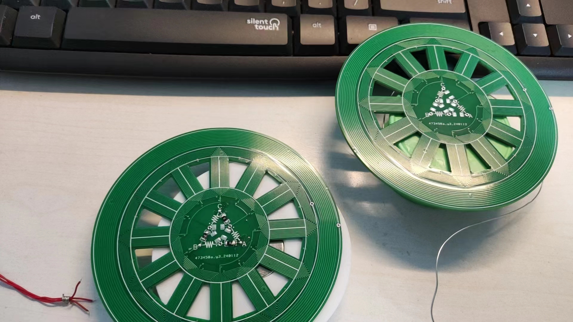
Finally, a brilliant solution came to mind: an axial magnetic field motor. A set of alternating N and S magnets is added to the float, driven by a PCB motor below. It's thin and suitable. Let's get started!
Features:
1. 12-slot 20-pole motor (magnet 15*5*2mm, purchase link: Neodymium iron boron strong magnet rectangular magnet high strength long strip magnet rare earth permanent magnet - Taobao (taobao.com)), motor winding calculator (Motorwicklungsschema berechnen (maltemedia.de)), coil characteristics are R single-phase resistance 27.3Ω, 0.38A@12V. However, the magnetic force of a single four-layer PCB is too small to control the levitation distance. Two PCBs need to be connected in parallel (specifically: solder two PCBs with delta connections, and then connect the inputs of the two boards together), 9.8Ω, 1.1A@12V. However, the distance is still less than 1cm for levitation, and the circuit needs to be raised by one more layer of board thickness.
Process: The motor coil is drawn by sketching in SolidWorks, then exporting a high-precision DXF, and then importing it into JLCPCB EDA as a single layer. Then, the second layer is obtained by horizontal mirroring. The third and fourth layers are similar. Then, the multi-layer coils are connected through through holes. The effective length of the coil is 15mm, which is the length of the magnet. The inductor spiral is done in the same way.
The windings are obtained through the winding calculator above. It is necessary to connect the same and opposite ends of the windings. This can also be derived by drawing a motor model. I used Geometer's Sketchpad:

2. Magnetic levitation float: Purchase a 500g load float (purchase link: Float 150g 300g 500g Magnetic Levitation Magnet DIY Strong Magnet Neodymium Iron Boron - Taobao (taobao.com)).
Process: This part is drawn in SolidWorks, and then exported as a Step model for 3D printing. When the magnet slot is about to be sealed, the printing is paused, and then the magnets are pasted. The magnets are NS alternating and pasted with 502 glue. As shown in the figure. A space is reserved in the float to place the wireless power supply coil, but it is not placed in the figure. A printed disk is used as a placeholder.

3. The center is changed to star or delta connection of the motor through a 0Ω resistor. The uppercase ABC ports are the motor's external output ports.
4. Add a wireless power supply inductor coil around it, approximately 20uH (theoretical value, no actual measurement). Calculator links (1. Planar spiral coil inductor calculator (circuits.dk) 2. PCB planar coil inductance value online calculation tool - RFID, NFC antenna design (edatop.com)). Number of turns (n): 10; turns Spacing between turns (s): 254um; Turn width (w): 508um; Outer Diameter (dout): 97240um. This part of the circuit was purchased (purchase link: Magnetic levitation wireless power supply module wireless power supply light moon light globe DIY accessories long distance - Taobao (taobao.com)).

The files include: PCB motor file *1, SolidWorks float model file *1, SolidWorks coil model file *1.
The STM32F030C8T6 core board features fully exposed I/O pins, a 1.44-inch LCD interface, and a NOR flash chip.
The ST Link V2/1 emulator is modified from the official ST development board schematic and is prohibited for commercial use.
 Other display images are also available.
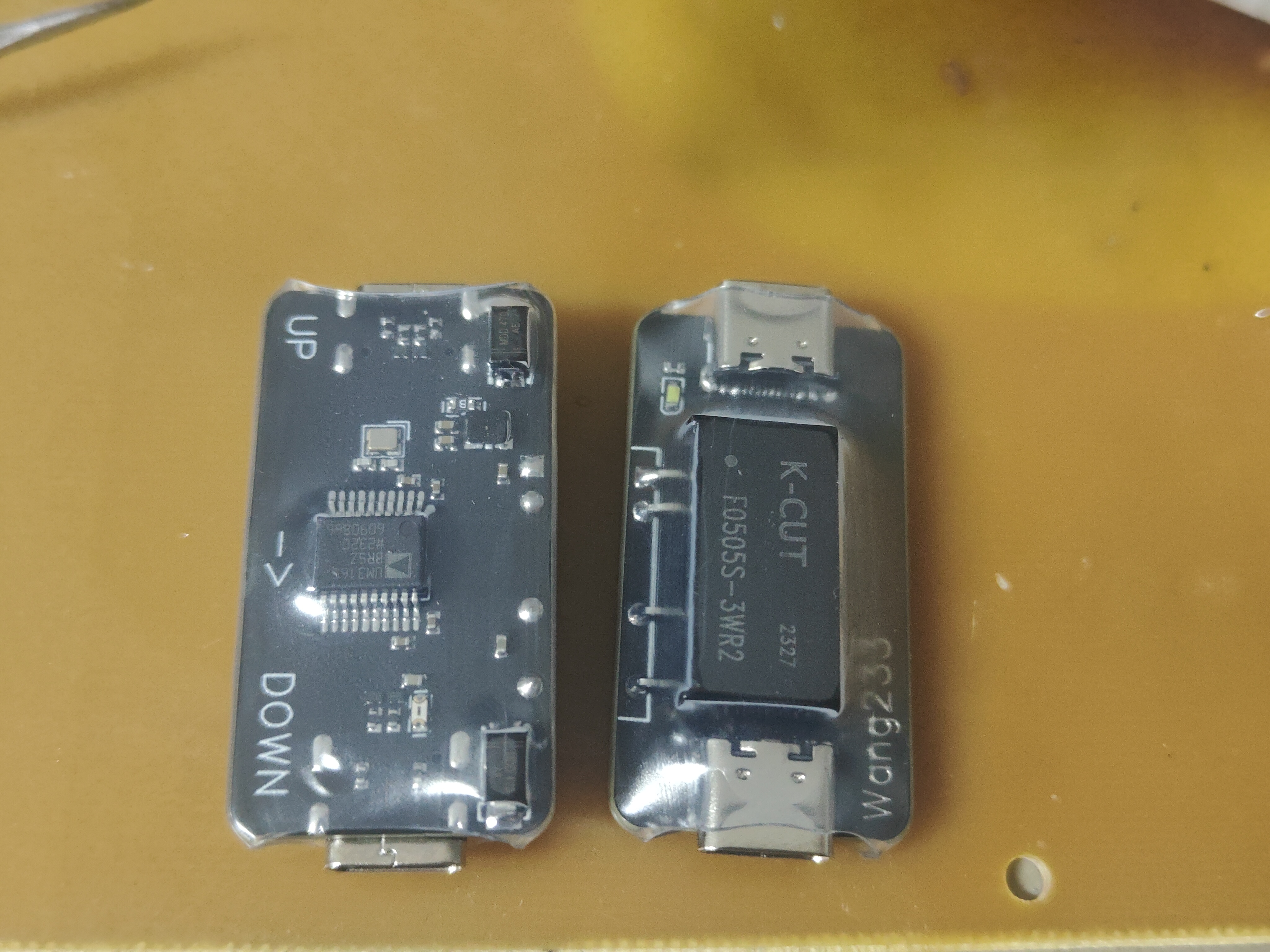 was tested for maximum transfer speed (external hard drive):
 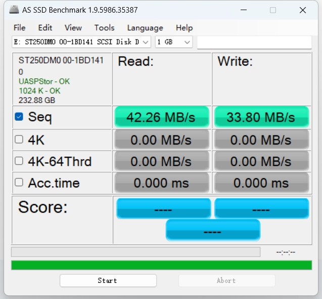 the LED indicates the host side, and the other end is the device side.
  Soldering and Assembly:
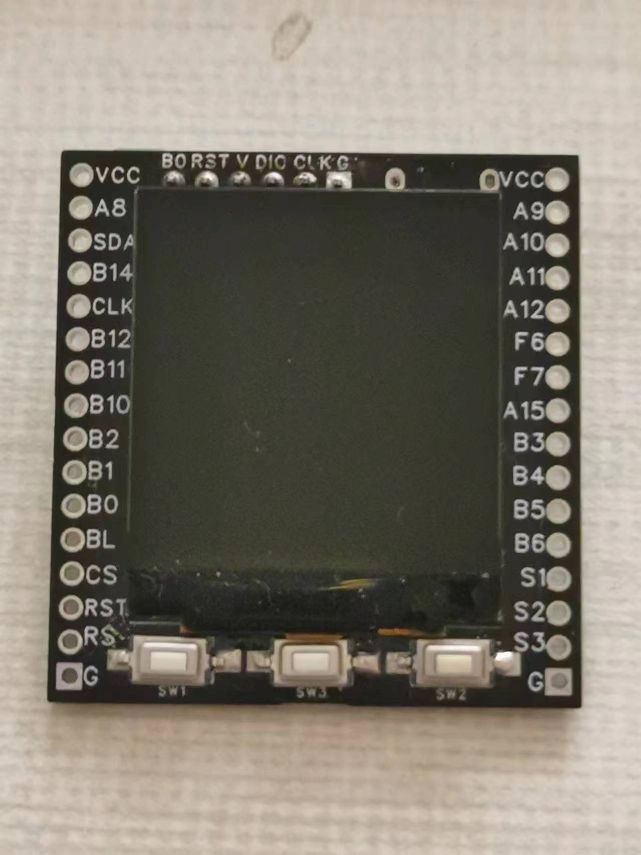
 The outer shell is 3D printed from JLCPCB resin, and the model has a wall thickness of less than 0.8mm. Accept the printing risks during printing;


 京公网安备 11010802033920号

 240-034-5-37PCENN-.080


