is an open-source RTK locator.
It's ready to use right out of the box and comes with a compatible display platform.
It supports mainstream CORS services such as Qianxun, Sixpoint, and China Mobile.
, selectable L1 and L5 dual-frequency positioning with centimeter-level accuracy.
, NMEA data uploaded to the Ntrip Caster platform for easy recording and viewing,
convenient for secondary development or contact us for customization. Interface definition:
6-pin connector: +5V, PPS, RX, TX, EVENT, GND.
1. Connect antenna and USB power supply.
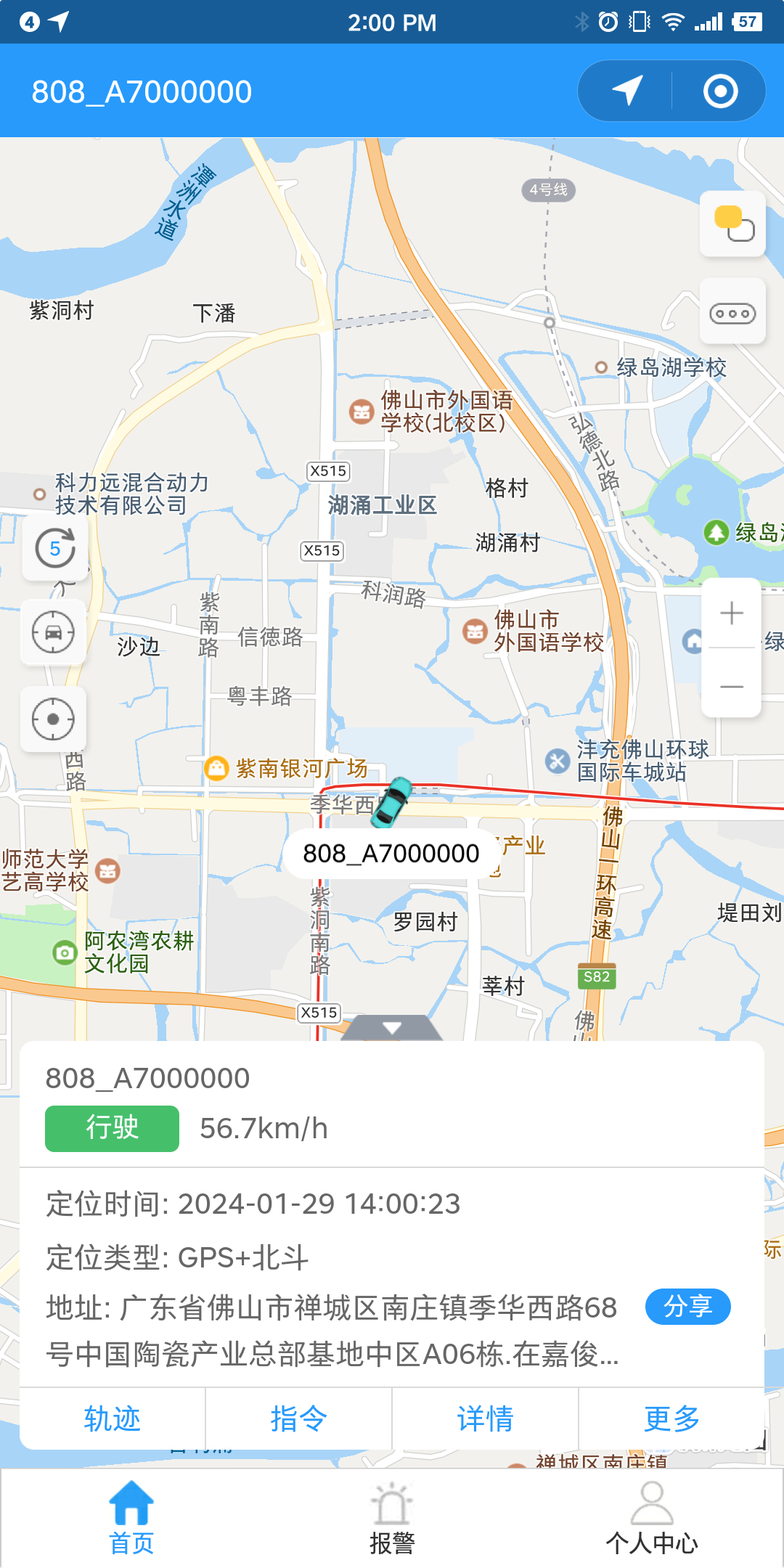
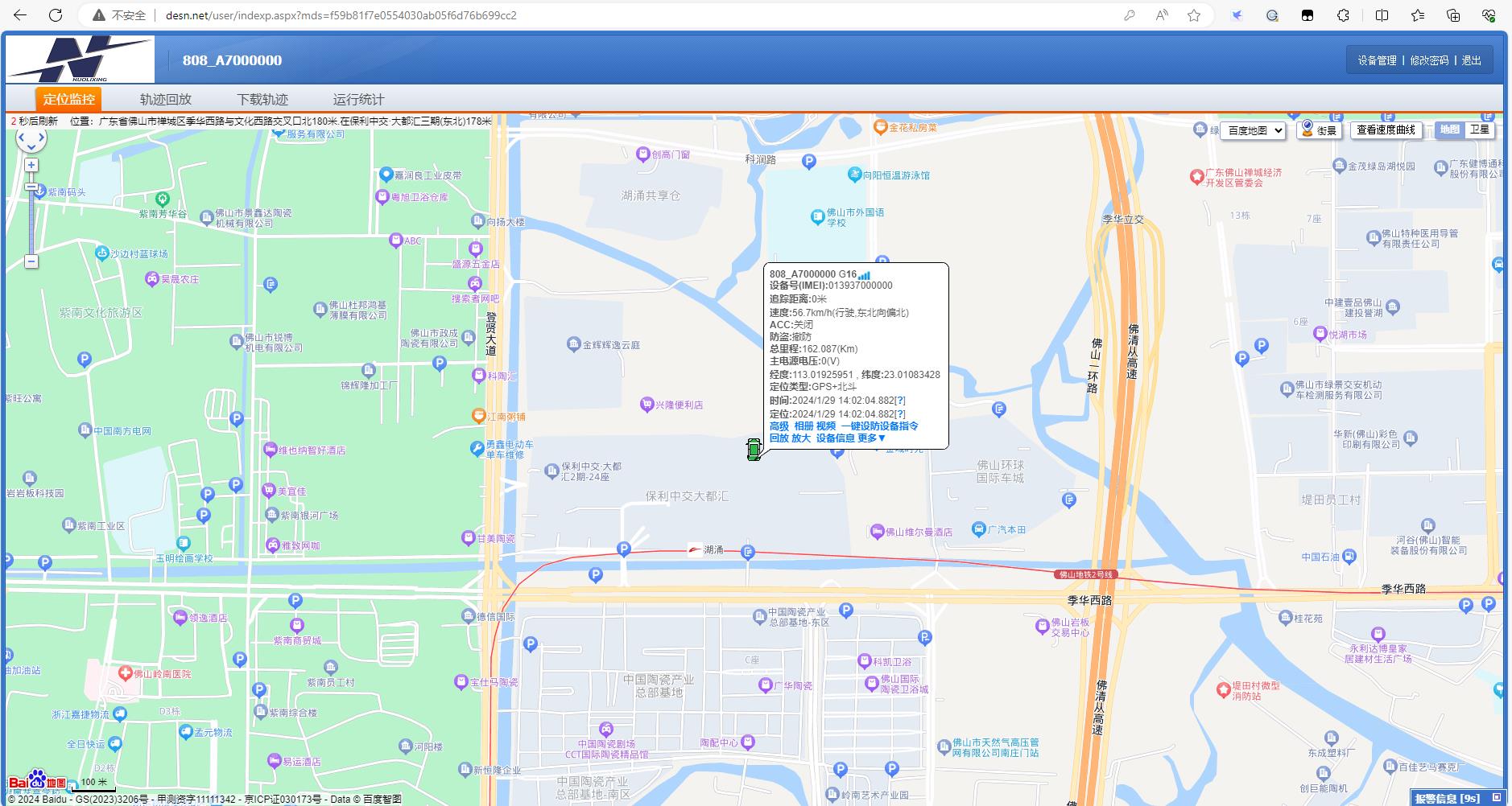
2. Log in to the platform to view positioning. Supports viewing the hardware schematic
via the Yunzhixing APP, mini-program, and webpage (http://desn.net/).
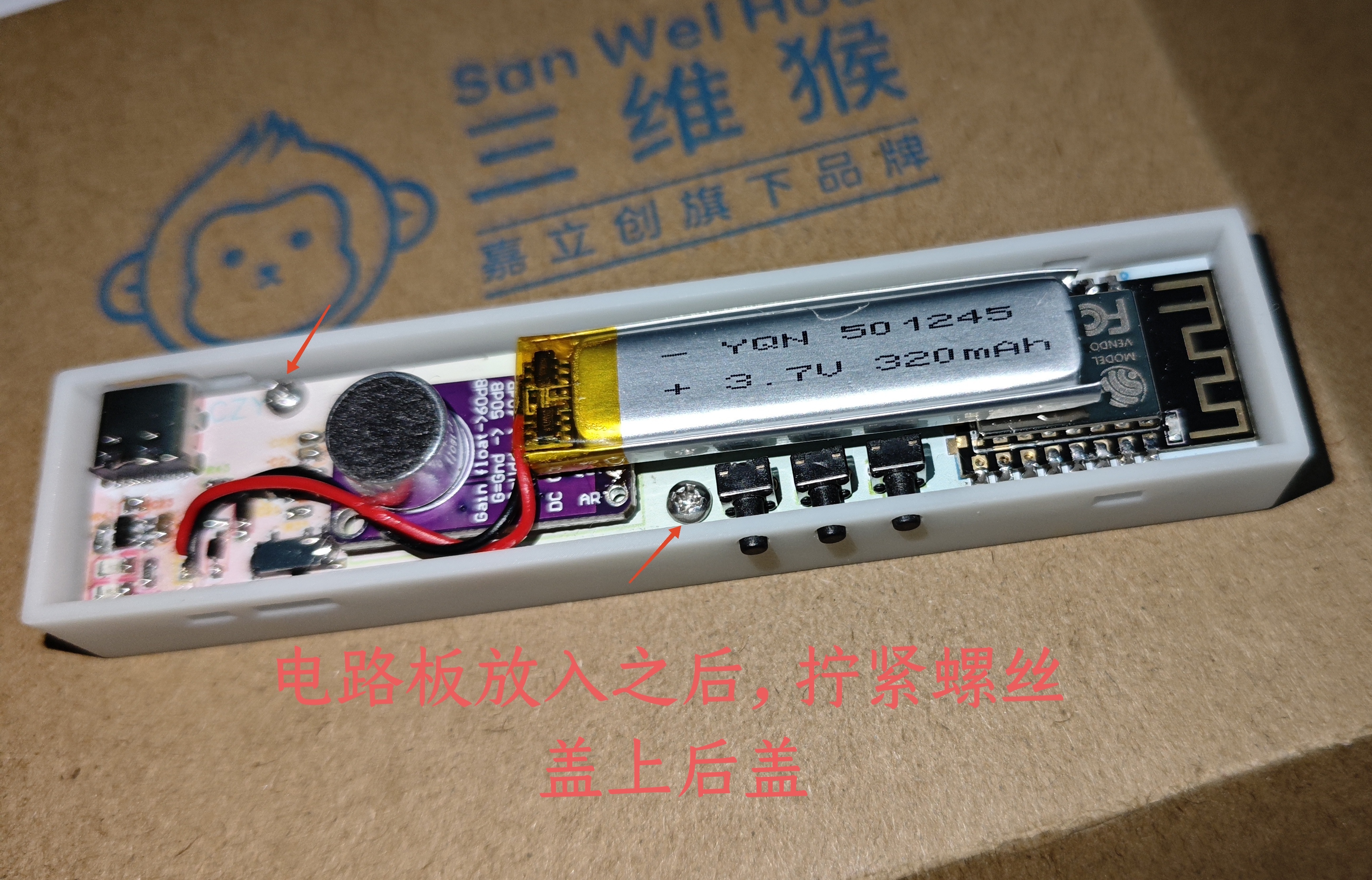
The project uses the ESP8266 module as the main controller and the WS2812B 2020 music rhythm LED strip as the LED beads. The peripheral circuit is simple; the casing is complete and can be programmed and modified, making it highly playable.
I. Project Introduction
This project cloned and modified the workshop director's rhythmic light strip. The first version was made a year and a half ago. It was relatively small, and the circuitry was working and verified to be usable. However, due to some issues with the casing design, the circuitry was not convenient for programming. Therefore, a second version was recently designed based on available materials. The biggest difference from the first version is the redesigned casing, which can be 3D printed directly. The snap-fit design makes assembly and disassembly easy, eliminating the need for screw posts, reducing size and cost.
Comparison of the two versions
: First version: The CH340 download circuit was omitted, making downloading and debugging slightly more complicated, requiring an external programmer, but the cost was relatively reduced; due to being a beginner, automatic wiring was used, resulting in messy wiring, but it was usable; calculation errors occurred during casing design, so the casing is barely usable but not ideal; a power switching circuit was missing, leading to situations where the battery is charged and discharged simultaneously, which is not very battery-friendly.
Second version: The second version specifically addressed the issues of the first version.
1. Added Automatic Download Circuit: An automatic download circuit for the CH340C was added, which has been tested and confirmed to be working. The original integrated MOSFETs were replaced with two NMOS transistors, simplifying soldering and eliminating the need for orientation identification. The program can be burned simply by connecting the automatic download circuit to the computer via a data cable; no download module or button operation is required, facilitating program debugging.
2. Optimized Layout and Routing: Layout and routing were completed in-house, resulting in a simpler layout and routing compared to the first version.
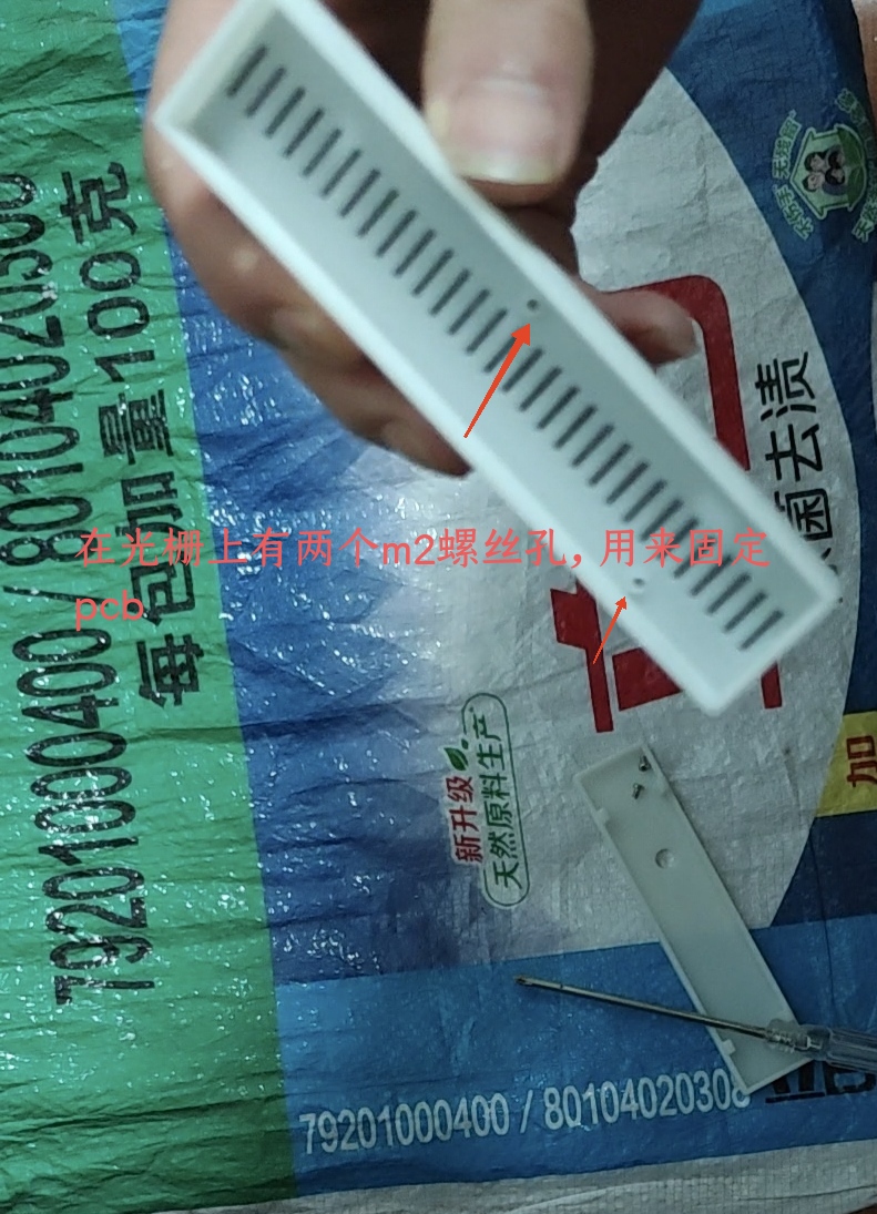
3. Housing Structure Design: The housing design was completed using JLCPCB EDA, achieving higher precision. The snap-fit structure was drawn using other housing software, and a grating was used to fix the PCB in place to prevent movement within the housing.
4. Added Power Switching Circuit: This circuit prevents the battery from using its own power during charging while allowing external power supply during charging, improving battery life and circuit safety.
5. Added Color Silkscreen Printing: Compared to the monochrome of the first version, the second version incorporates color silkscreen printing, making the PCB more visually appealing.
6. Complete Project Information: The information is organized, and the purchase of all materials (except the casing, which is included in the accessories and can be printed at JLCPCB) is listed in a convenient inventory list.
Advantages and Disadvantages: Disadvantages: The total cost of materials is approximately 90 (including capacitors and resistors; if you have your own capacitors and resistors, it will be about 10 yuan cheaper; this is the cost of one set, and the average cost will be lower if you make several sets). The cost per set is relatively high, and the cost-effectiveness is lower compared to prices on Taobao. The WS2812 package is small and not easy to solder.
Advantages: Complete information allows for DIY and enjoying the entire production process; the circuit is simple and easy to understand, and can be added to or modified; the code is publicly available, simple and easy to learn, and you can also learn about the ESP8266 module; there is an automatic program download circuit, which can be used to burn programs at any time with just a data cable.
II. Circuit Section
The circuit section mainly consists of a charging circuit, a power switching circuit, an audio source acquisition circuit, an automatic download circuit, a main control circuit, an LDO step-down circuit, and the WS2812 circuit.
1. Main Control
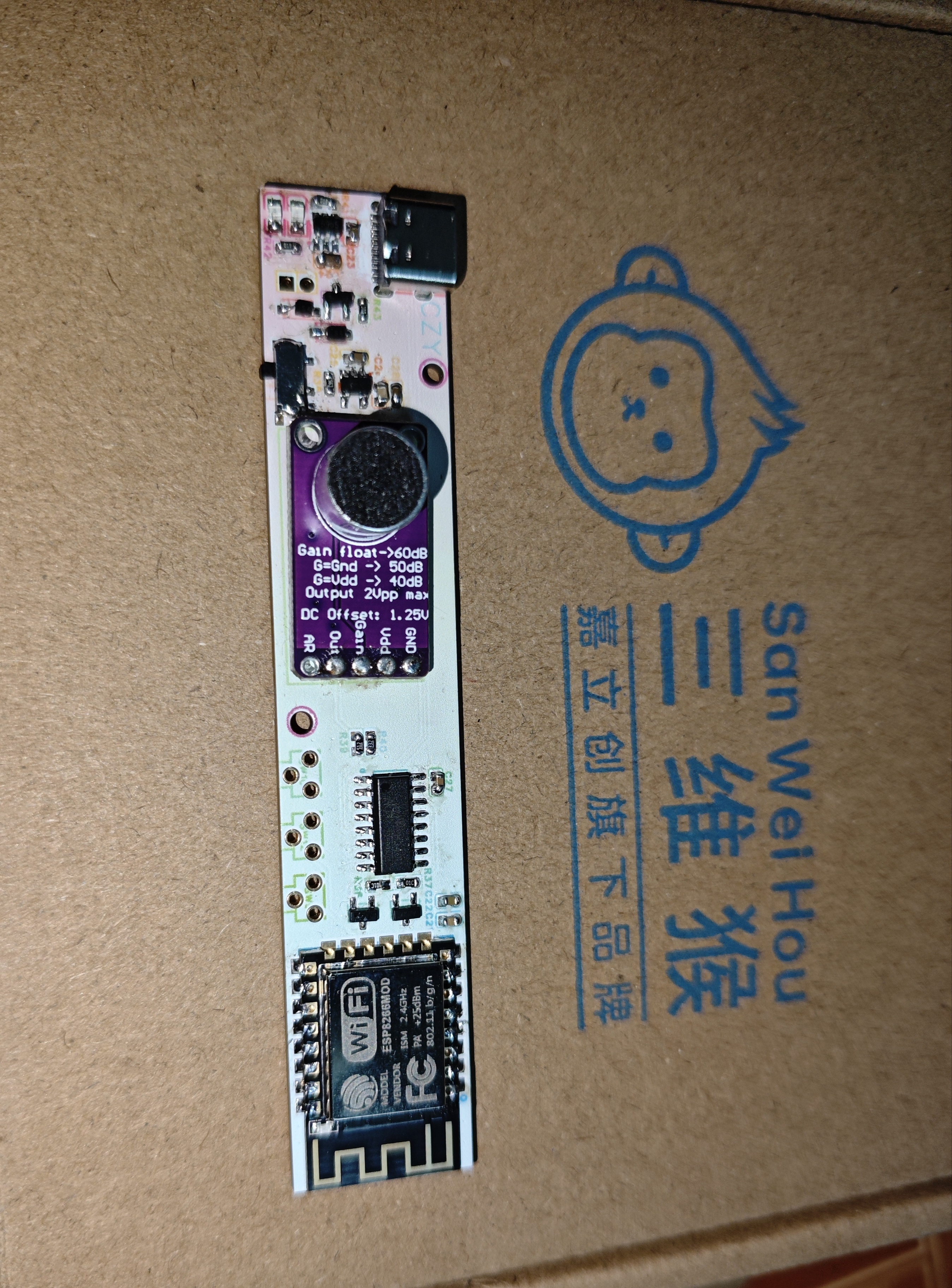
Circuit: The main control circuit uses the ESP8266 module. This module is small in size, has simple peripheral circuitry, can be programmed using Arduino, and is easy to learn. It is also easy to solder, inexpensive (around 5 RMB on Taobao), and offers multiple functions, making it an ideal choice for DIY beginners and suitable for many projects.
10K pull-up resistors are connected in series on the TX, RX, and IO0 networks. The pull-up resistors on TX and RX ensure more stable data transmission. IO0 is equivalent to the chip's BOOT pin; a low level enters the programming mode, and a high level enters the working mode, hence the need for a pull-up level. The right side of the diagram shows the reset and filtering circuits. The filtering circuit ensures stable operating voltage for the module, and the reset circuit ensures stable operation. The 100NF capacitor connected in series determines the pin power-on sequence. Since the capacitor charges upon initial power-on, these two pins will power on slightly later than other pins. This not only ensures module stability but also serves in the subsequent automatic program download process.

2. The automatic download circuit
uses the CH340C's driver circuit, powered by 3.3V. The external circuitry is simple; compared to the CH340G, it eliminates the need for a crystal oscillator and start-up capacitor. Compared to the CH340N, it adds RTS and DTR pins, enabling automatic downloading. Downloading the program via serial port primarily involves first putting the chip into program burning mode, then downloading the program via serial port. Therefore, manual downloading typically includes a reset button and a BOOT button; while automatic downloading uses two resistors and two NMOS transistors (as shown in the diagram below) to replace the manual downloading operation. Principle: Based on the conduction characteristics of NMOS, we know that when RTS is high and DTS is low, Q13 conducts while Q12 does not, resulting in IO0 being low and EN being high. Conversely, when RTS is low and DTS is high, Q12 conducts while Q13 does not, resulting in IO0 being high and EN being low. Following this principle, during download, the CH340C chip first sets RTS low and DTS high, resulting in EN being low and the main control chip circuit resetting. Then, it sets RTS high and DTS low, resulting in IO0 being low. While EN should be high, due to the charging of the 100NF capacitor in the reset circuit, EN remains low for a very short time (reset state). When EN returns to high, IO0 remains low, thus entering program download mode. (Regarding whether to use the RST or EN pin for reset, theoretically either is fine, but the official recommendation is to use the EN pin, so the EN pin is used here.)

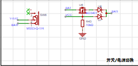
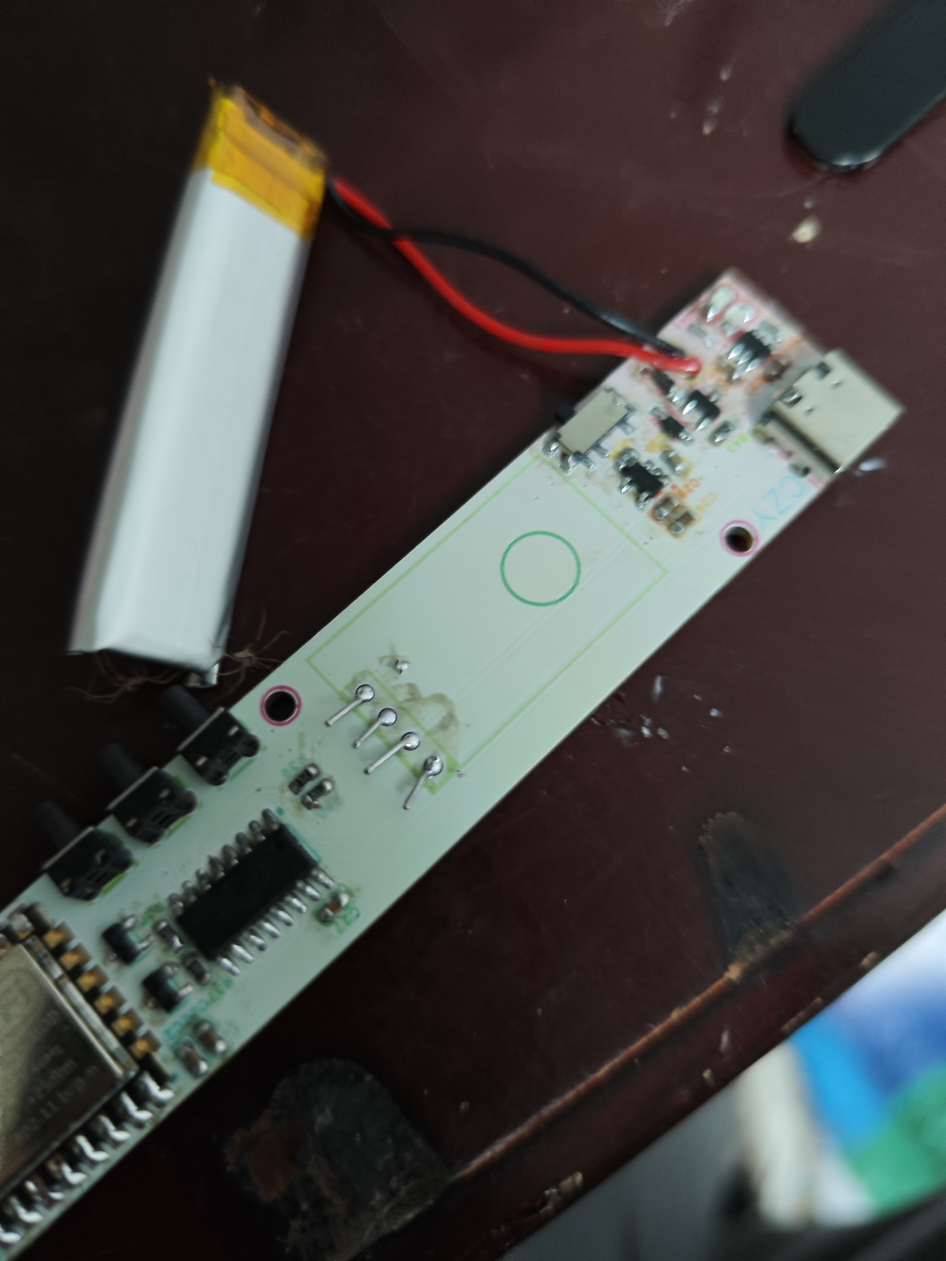
3. Power Switching Circuit:
Due to the limited battery life (a few hours), but sometimes you still want to use the battery when it's empty, you have to charge and use it simultaneously. This causes the battery to heat up, accelerates battery aging, and is also unsafe. To avoid these problems, a power switching circuit is added to the design. When charging, an external power supply is used, and the battery is not used. Charging and use can be done simultaneously. The battery has a battery protection chip, so there is no need to worry about overcharging in the short term. Principle: A PMOS transistor is used here, connected to a resistor pulled down to ground. When there is no external power supply, the MOS transistor is turned on, and the battery powers the battery. When an external power supply is connected, the resistor pulls up, the MOS transistor is turned off, and the external power supply powers the battery.
4. 3.3V Buck Circuit:
Used to step down the voltage to 3.3V. The voltage drop is small, suitable for 3.7V lithium batteries. The external components are simple, and it can provide a maximum current of 600mA, which is sufficient to power the main control module and the audio source acquisition module.

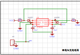
5. The charging circuit
uses the TP4059 charging chip, which is compact and has a simple peripheral circuit.
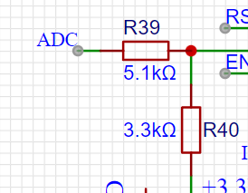
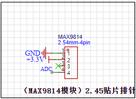
6. The audio acquisition circuit uses
an external MAX9814 module, ensuring stable signal acquisition and easy soldering. R40 is a pull-down resistor for more stable signal transmission, and R39 protects the pins of the main control module chip and also provides some impedance.
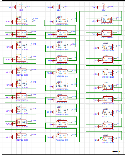
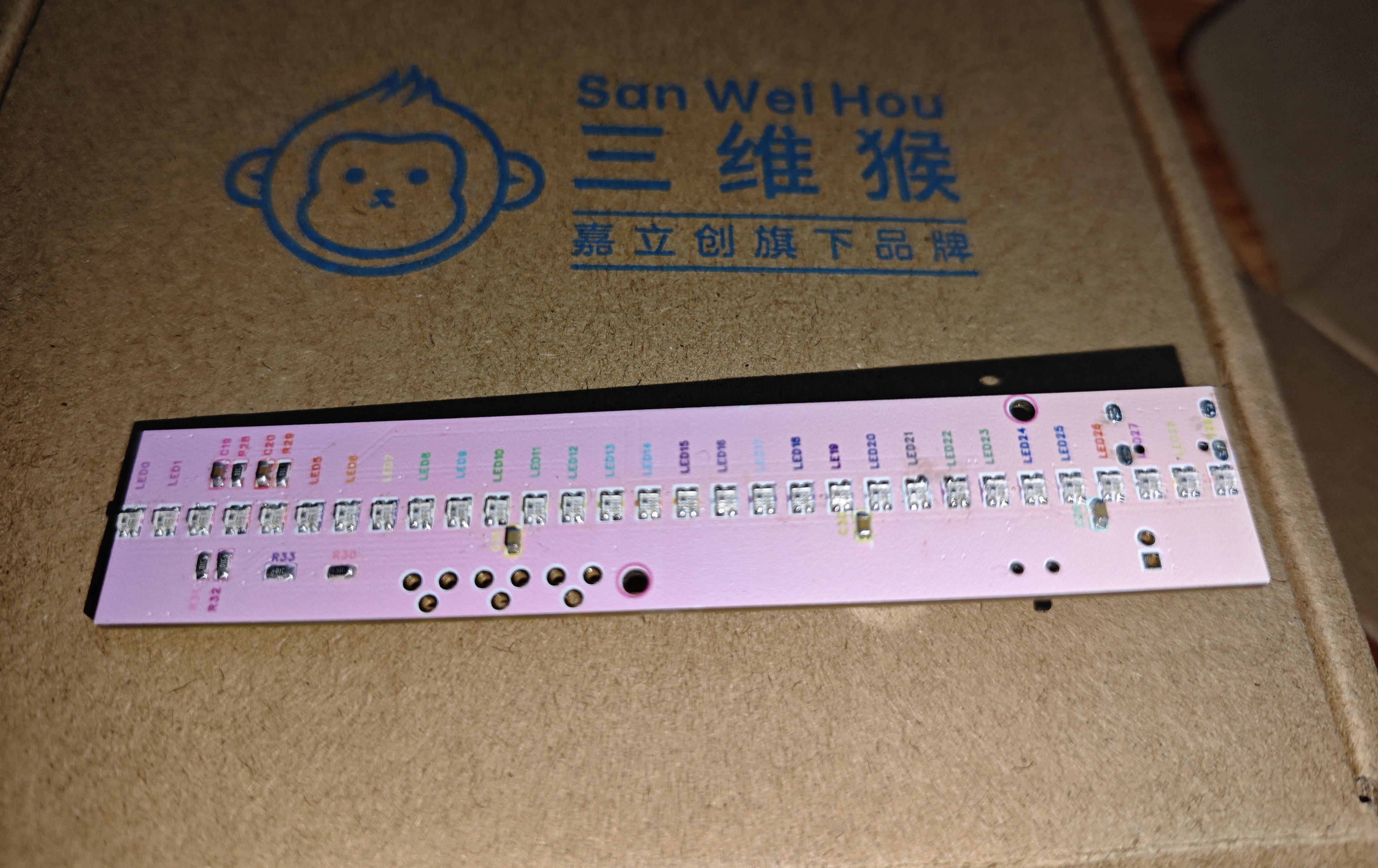
7. The WS2812 LED circuit
uses bus control; one I/O port can control the color of all LEDs. It has a wide power supply range (3.3-5.5V) and can use battery power or 5V power. Three filter capacitors ensure circuit stability.
III. Program Section
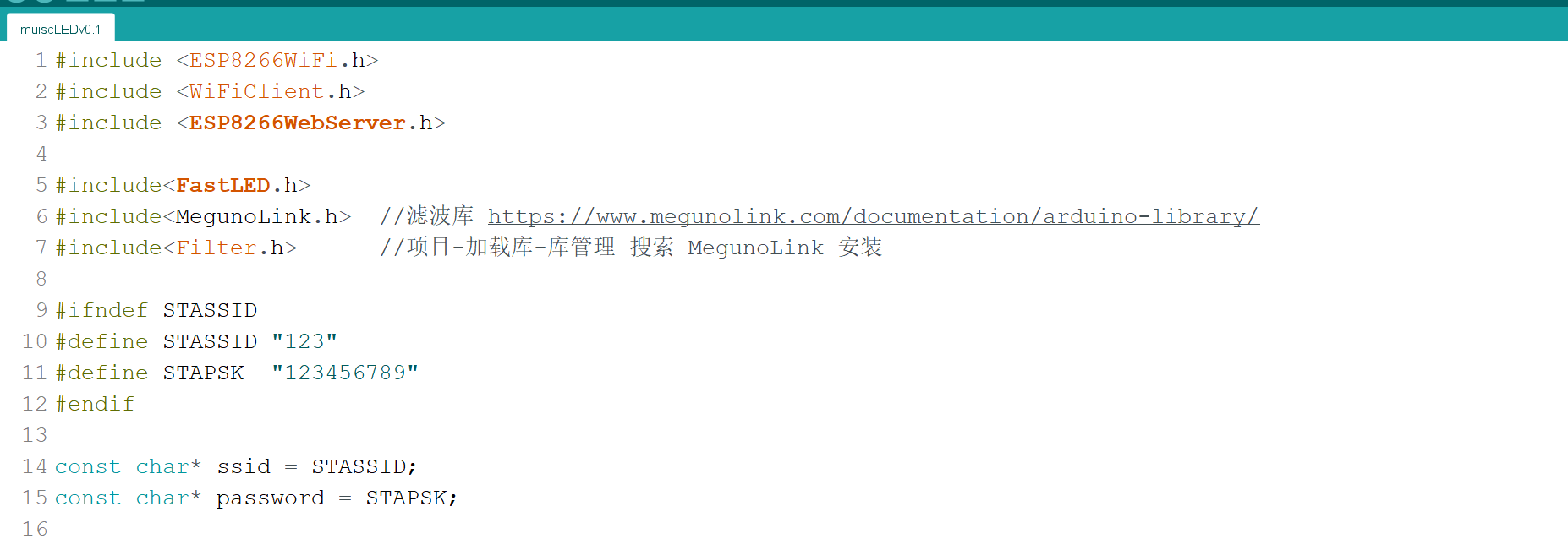
: Library File References and Data Definitions.
Program initialization

outputs LED color gradient data.

Based on the audio acquisition value, it converts the maximum height of the LED strip display
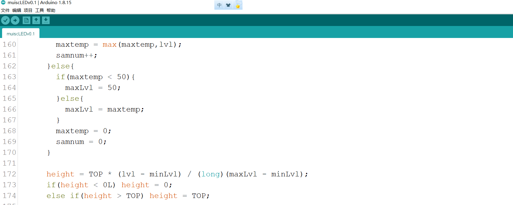
and switches the display mode.

Develop an HTML webpage interface for
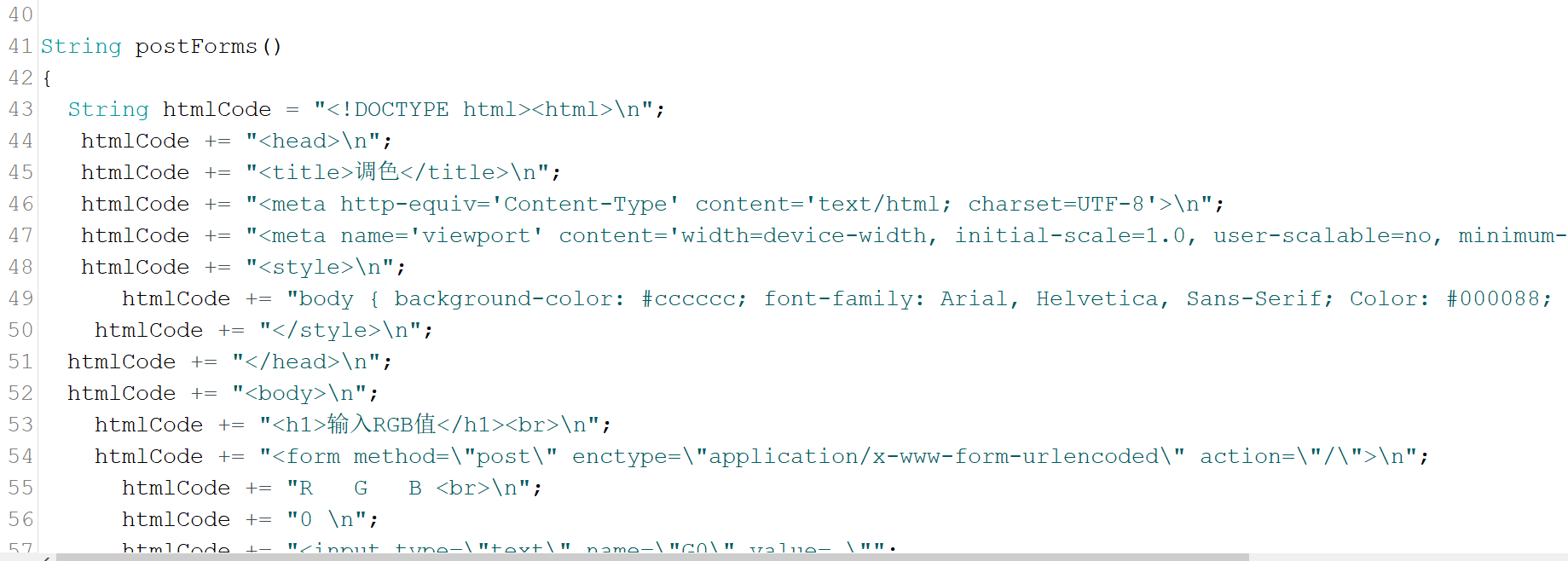
switching the LED strip color to a webpage-based color modification mode and automatically connecting to Wi-Fi.

IV. Soldering and Structural Assembly Instructions
: Soldering: Due to the small package size of the WS2812 LED, although an electric arc soldering iron can be used, it is recommended to use a hot air gun or heating table if possible, as it is faster and more convenient (of course, experienced users can disregard this). If using a heating table, you need to solder the front side first. After soldering, you need to check if the LED has solder joints or obvious cold solder joints (these are subtle and can only be detected upon power-up). This is crucial; otherwise, the LED may smoke upon power-up. I didn't check when soldering the second piece, and as a result, one diode lit up immediately upon power-up. Using a multimeter, I found several LED pins had solder joints. After cleaning the solder joints, the LED returned to normal.
On the PCB front side, after soldering, first check if the positive and negative terminals of the LED are short-circuited, and then test continuity. Normally, the four pins of each LED should not be connected. If two pins have zero resistance, it indicates solder joints and needs to be addressed.
The back of the PCB contains the main circuitry. Compared to the front, this side is much easier to solder, but there are two details to note. It's best to solder the Type-C connector first, as soldering the 16-pin Type-C connector is prone to solder bridging, requiring drag soldering. If components have already been placed on the back, drag soldering the Type-C connector might be inconvenient. Also, when soldering the MAX9814 module, try to solder the header pins first (vertically). After soldering, solder the module onto the header pins. This makes it easier to adjust the header pin length; any excess pins need to be trimmed. Solder the module close to the PCB to accommodate the battery.
If you are confident in your skills, you can leave a section of solder on the pad, straighten it, and then use this to fix the MAX9814 module. This method is more difficult and may result in cold solder joints if not done correctly. For
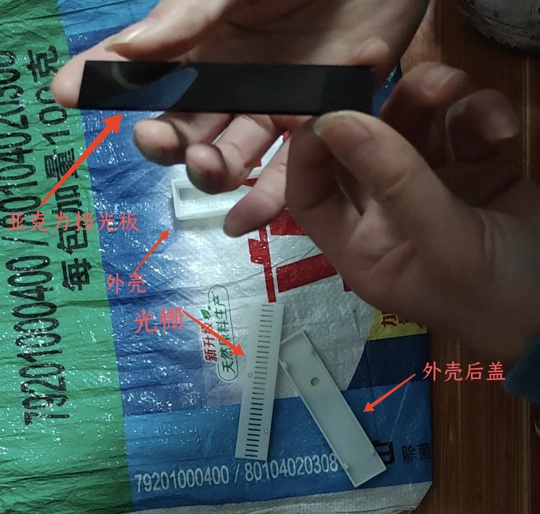
structural assembly
, first place the acrylic light-blocking plate, then place the grating, with the flat side facing the acrylic and the side with the studs facing the PCB. Due to printing precision errors, the grating may tilt after placement. You can lightly sand the sides, but it can also be used without sanding.
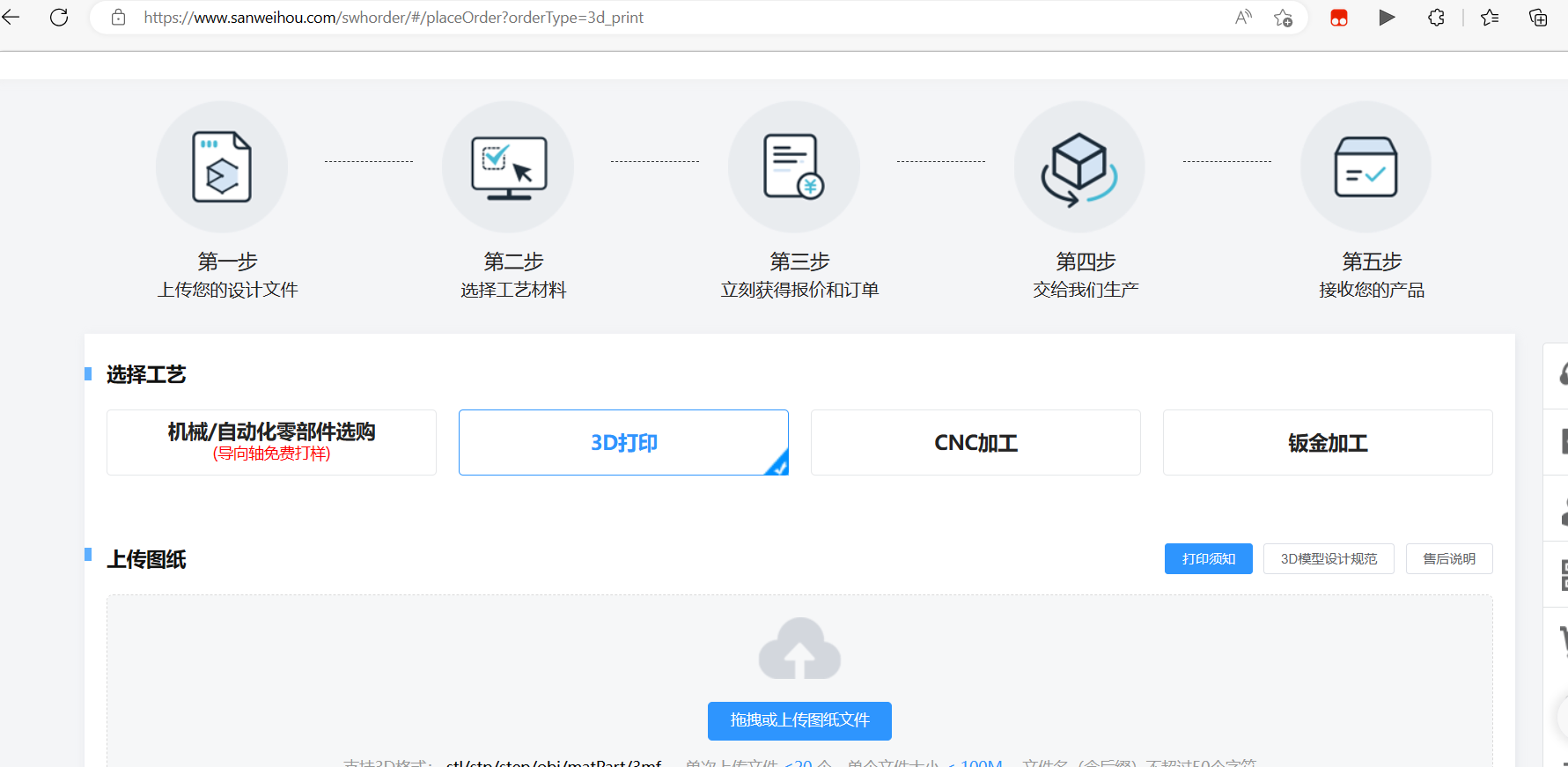
V. PCB and Housing Ordering
PCB Ordering:
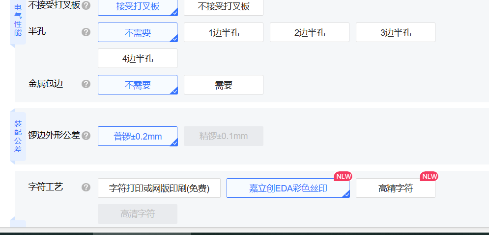
The PCB for this project can be ordered with or without color silkscreen printing. If color silkscreen printing is not required, simply place the order directly. If color silkscreen printing is required, please note the following options:
change the solder mask color to white, change the solder pad tin spraying to immersion gold, and change the character printing process to JLCPCB EDA color silkscreen printing.

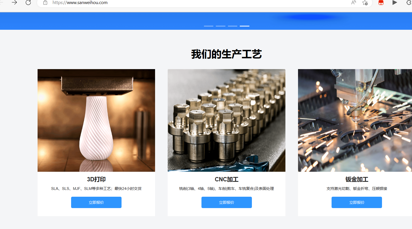
Housing printing
will be done at JLCPCB's 3D Monkey factory; the price is inexpensive and the quality is quite good. The housing file is attached; download, unzip, and upload the file for printing.

A high-definition demo video is available on Bilibili: https://b23.tv/YmpKcLm
Original author: Rhythm Light Strips - JLCPCB EDA Open Source Hardware Platform (oshwhub.com)
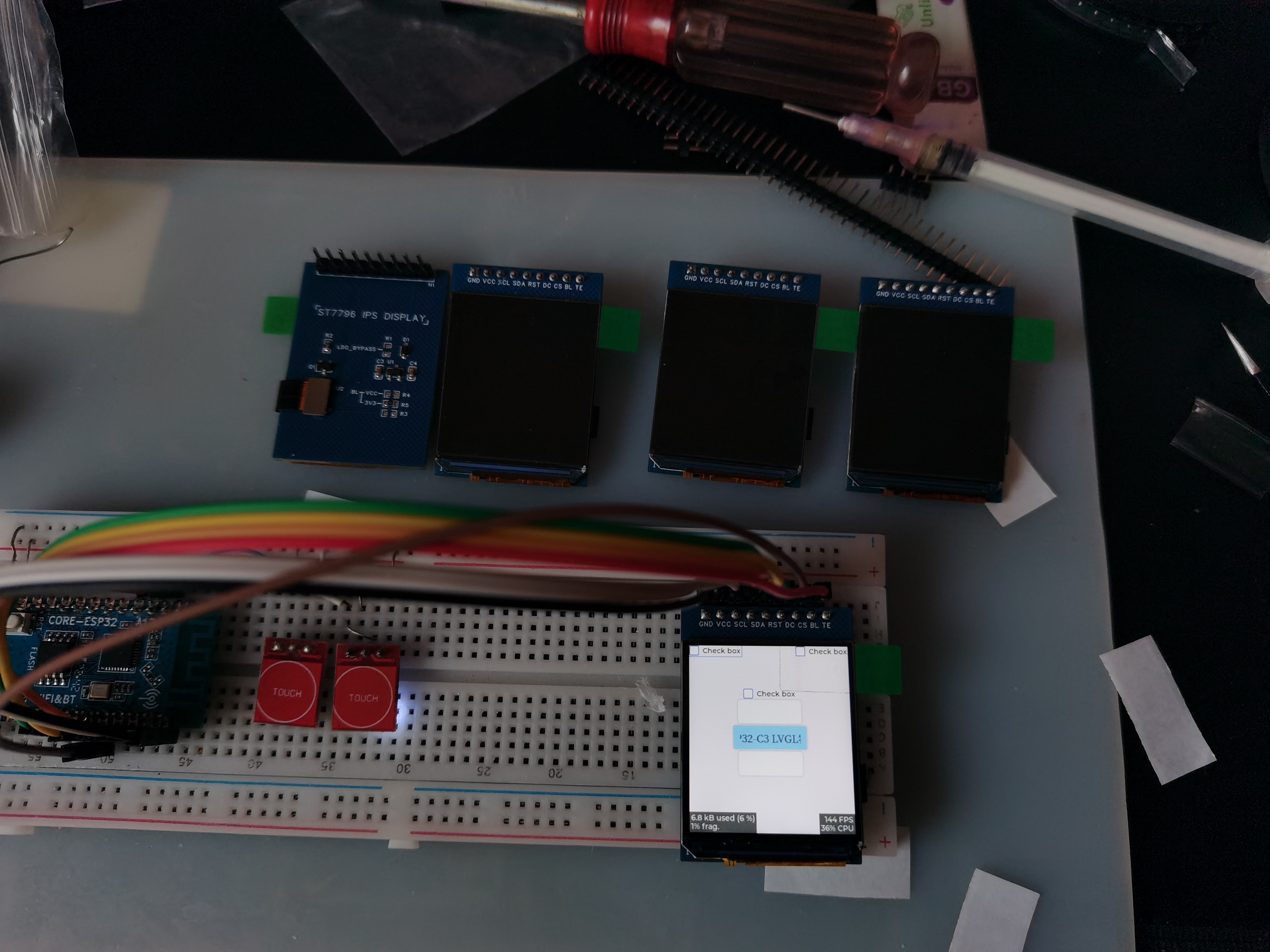
The display looks good, but unfortunately it's out of stock.
PDF_Old Wang ST7796 320_360 IPS Screen Adapter Board.zip
Altium_老王ST7796 320_360 IPS screen adapter board.zip
PADS_Old Wang ST7796 320_360 IPS Screen Adapter Board.zip
BOM_老王ST7796 320_360 IPS Screen Adapter Board.xlsx
96201
Snowflake lamp
Circuit for controlling LED blinking using a 6021WS touch chip
Touch-activated snowflake light achieved through a 6021WS touch chip and solid copper touch pads.
ea5ef4b6974ca38035e0e2508ef55c78.mp4
PDF_SnowflakeLantern.zip
Altium_snowflake.zip
PADS_SnowflakeLamp.zip
BOM_SnowflakeLamp.xlsx
96202
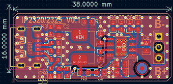
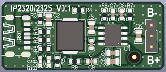
2-3 series battery charging IP2320 2325_V0.1
USB 5V input, synchronous boost, charging 3-cell batteries, battery terminal current approximately 1A, charging power approximately 14W.
Function Description:
USB 5V input, synchronous boost, charges 3-cell batteries, battery terminal current approximately 1A, charging power approximately 14W.
Input voltage
4.5~5.5V. 20V Max. 4.5V triggers undervoltage protection, automatically reducing charging power.
Output voltage
3*(4.2/4.15/4.1/4.05V±0.05V) (other specifications can be customized) .
Trickle charging
threshold 3*(3.0V±0.05V), trickle current 100mA±50mA,
full charge cutoff
200mA±100mA. (When the chip output reaches 12.6V but the battery voltage does not, the charging process switches from constant current to constant voltage. The higher the internal resistance of the battery cell and wires, the longer the constant voltage charging time.)
The LED
output is high during charging and low when fully charged; it will flash in case of an abnormality.
NTC
does not support
chip over-temperature
protection; it has built-in over-temperature protection up to 135℃.
USB voltage,
USB current, battery voltage ,
battery current , charging power, charging efficiency: 4.80V 2.31A , 9.97V 1.04A , 11.09W , 93.51%; 4.75V 2.96A , 12.39V 1.03A, 14.06W , 90.77%. Charging temperature . Schematic diagram , PCB layout, PCB 3D preview, PCB physical image.


Demo-2325_V0.1_Gerber_240107.zip
Demo-IP2320 2325_V0.1_240107.pdf
Demo-IP2325_V0.1_BOM_240107.html
IP2325-3S Charging Curve.xlsx
IP2325 datasheet v1.15.pdf
IP2320 datasheet v1.00.pdf
IP2325_3S datasheet v1.15.pdf
PDF_2-3 Series Battery Charging IP2320 2325_V0.1.zip
Altium_2-3 Series Battery Charging IP2320 2325_V0.1.zip
PADS_2-3 Series Battery Charging IP2320 2325_V0.1.zip
96203
51 Development Board V1.3
Using the CH340N to serial port chip, one-click programming is supported.
The board's shape is based on WCH's development board, which I thought looked cool, so I designed my own 51 microcontroller. The main control chip is an LQFP-packaged STC89C52RC. So far, I haven't encountered any problems. If you encounter any strange bugs while using it, please leave a comment. My drawing isn't very good, so please point out any shortcomings and I'll fix them QAQ.
Oh, and the fuses on the board don't need to be soldered; you can just connect them with a lump of solder, which saves time QAQ.

PDF_51 Development Board V1.3.zip
Altium_51 Development Board V1.3.zip
PADS_51 Development Board V1.3.zip
BOM_51 Development Board V1.3.xlsx
96206
electronic

 configuration includes:
 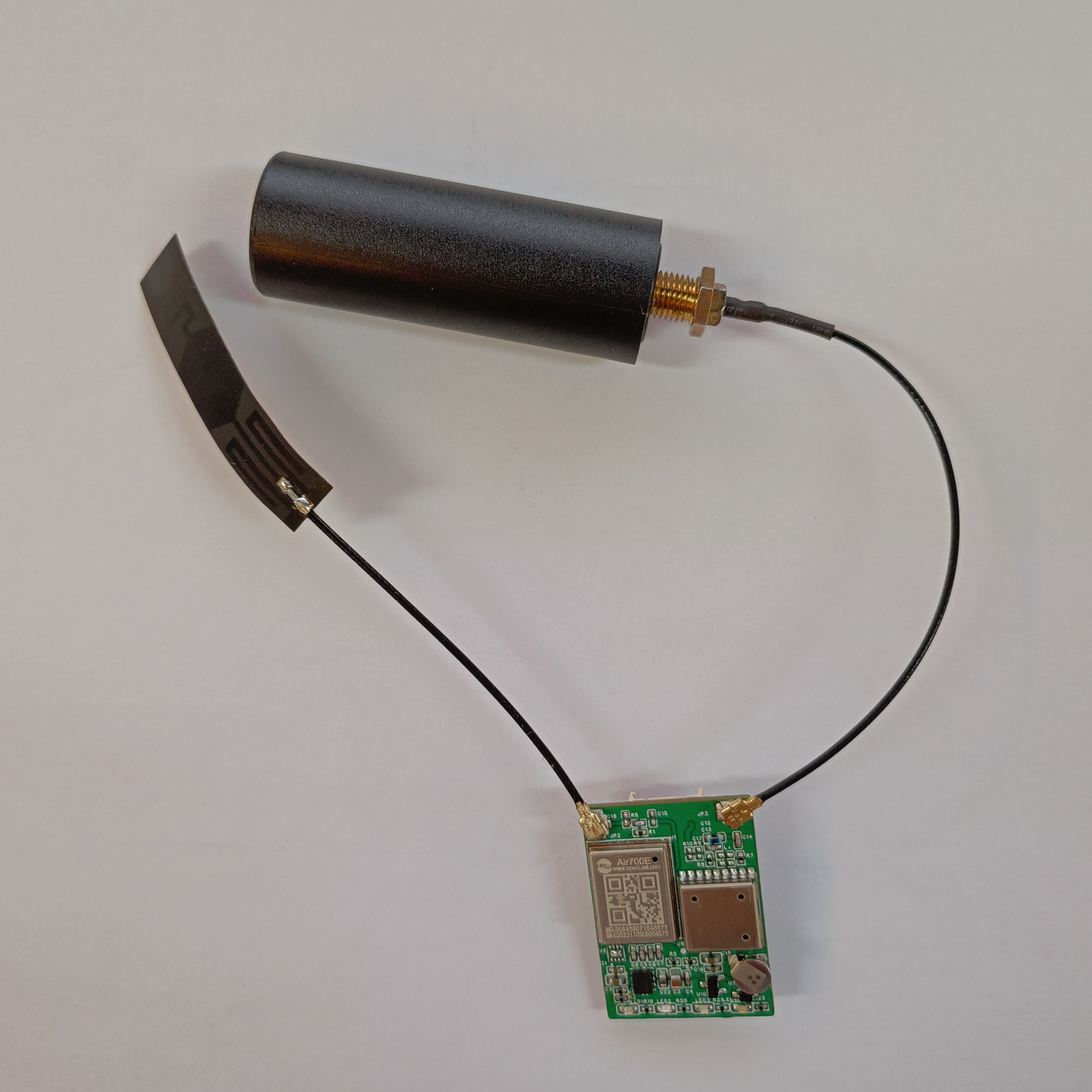 2. Log in to the platform to view positioning. Supports viewing the hardware schematic


 京公网安备 11010802033920号

 MB-232-015-156-4A00


