1.
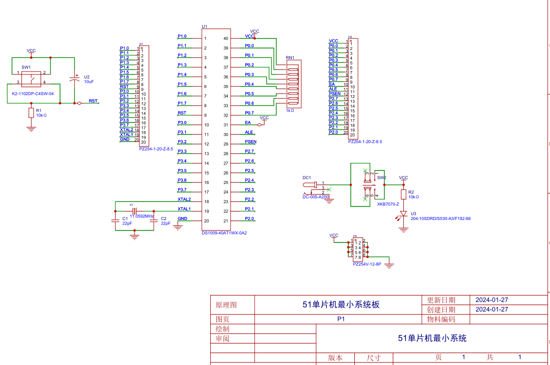
Reset Circuit
Purpose: The reset circuit of a microcontroller is similar to the restart function of a computer. When a computer freezes during use, pressing the restart button restarts the internal program from the beginning.
Similarly, when a microcontroller system malfunctions due to environmental interference, pressing the reset button automatically restarts the internal program.
Working Principle: In a microcontroller system, the system resets once upon power-on. Pressing the button resets the system again, and releasing and then pressing it again will reset the system once more. Therefore, the reset can be controlled by opening and closing the button during operation.
Power-on Reset: In the circuit diagram, the capacitor is 10uF and the resistor is 10kΩ. According to the formula, the time required for the capacitor to charge to 0.7 times the power supply voltage (the microcontroller's power supply is 5V, so 0.7 times is 3.5V) is 10kΩ * 10uF = 0.1s.
That is, within 0.1s of the microcontroller's startup, the voltage across the capacitor increases from 0V to 3.5V. At this point, the voltage across the 10K resistor decreases from 5V to 1.5V (the sum of voltages across the series circuit is the total voltage).
In the 51 microcontroller, a voltage signal less than 1.5V is a low-level signal, while a voltage signal greater than 1.5V is a high-level signal. Therefore, within 0.1 seconds of power-on, the microcontroller system automatically resets (the high-level signal received by the RST pin lasts approximately 0.1 seconds).
Button reset: 0.1 seconds after the microcontroller starts up, the voltage across the capacitor continues to charge. At this time, the voltage across the 10K resistor is close to 0V, and RST is at a low level, so the system works normally.
When the button is pressed, the switch is turned on, and a circuit is formed across the capacitor, short-circuiting it and allowing it to release the previously charged charge.
Over time, the capacitor voltage drops from 5V to 1.5V, or even lower, within 0.1 seconds.
According to the principle that the voltage across the series circuit is the sum of voltages across the series circuit, the voltage across the 10K resistor is 3.5V, or even higher, at which point the RST pin receives a high level again, and the microcontroller system automatically resets.
2.
Crystal Oscillator Circuit: The crystal
oscillator provides the operating signal pulses to the microcontroller, which determine the microcontroller's operating speed. For example, a 12MHz crystal oscillator means the microcontroller operates at 12MHz per second.
The oscillation circuit formed by the crystal oscillator and the microcontroller's XTAL0 and XTAL1 pins generates harmonics. While these harmonics have a minor impact on the overall circuit, they can reduce the stability of the clock oscillator.
To improve circuit stability, Atmel (the manufacturer of the 89C51 series) recommends connecting two 10pF-50pF ceramic capacitors to the two pins of the crystal oscillator and grounding them to reduce the impact of harmonics on circuit stability. Therefore, the capacitors in the crystal oscillator circuit can be between 10pF and 50pF.
3.
Pull-up
Resistors for Port P0: When Port P0 is used as an I/O port output, a low output level is 0, and a high output level is a high configuration (not 5V, equivalent to a floating state). This means Port P0 cannot truly output a high level to provide current to the connected load. Therefore, a pull-up resistor (a resistor connected to VCC) must be connected, and the power supply provides current to the load through this pull-up resistor.
Since Port P0 does not have an internal pull-up resistor and is open-drain, regardless of its driving capability, it is essentially without power and requires external circuitry to provide it. In most cases, a pull-up resistor must be added to Port P0.
Precautions for using Port P0:
1. Generally, when Port P0 of a 51 microcontroller is used for address/data multiplexing, a pull-up resistor is not required.
2. When used as a general I/O port, a pull-up resistor must be connected because it lacks an internal pull-up resistor.
3. When Port P0 is used to drive a PNP transistor, a pull-up resistor is not required.


 京公网安备 11010802033920号

 10121750-2101221LF


