
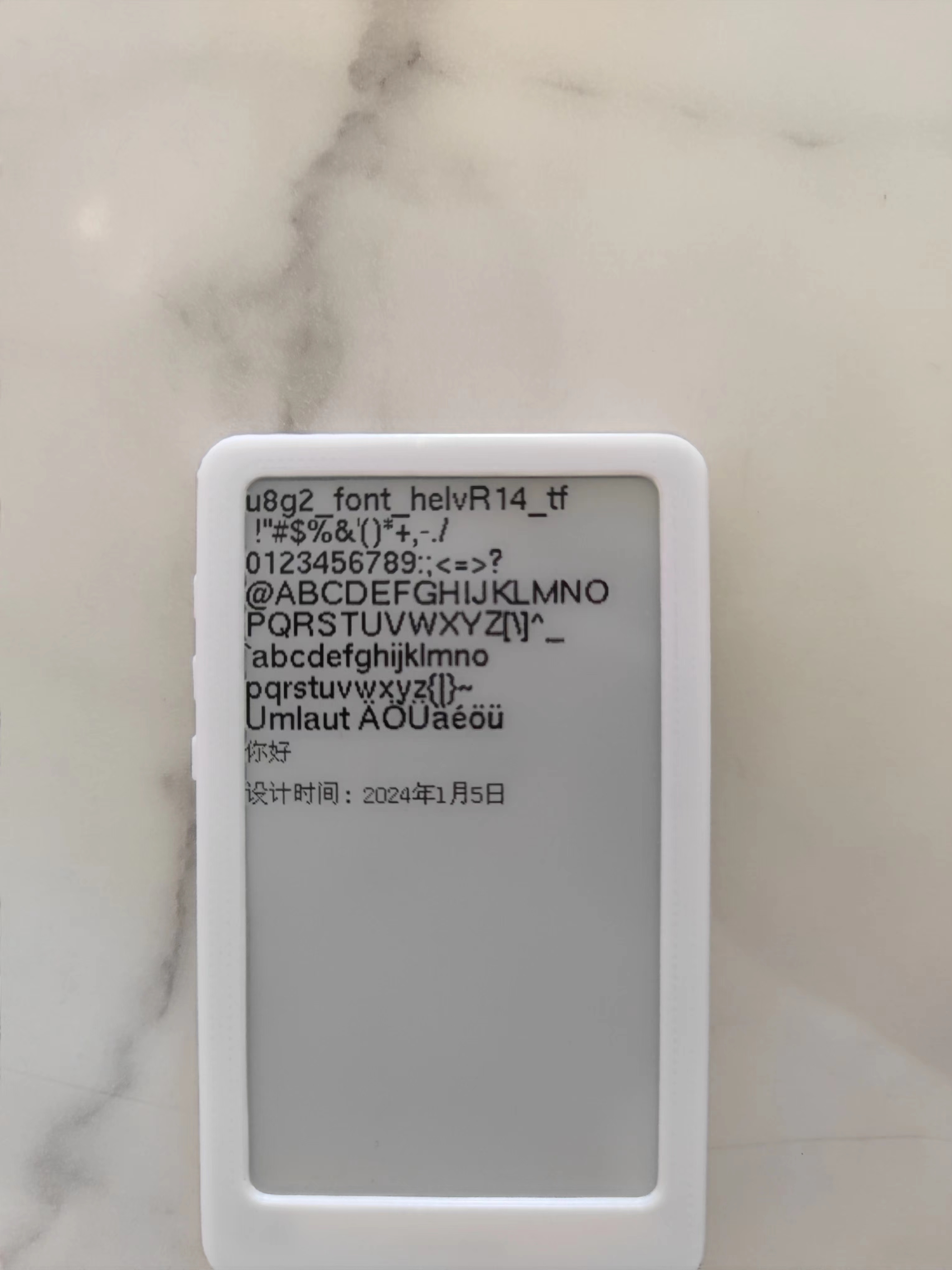
The charging/discharging
board provides charging/discharging circuitry and a battery terminal for battery power. It also has an SD
card
slot, allowing you to read SD card content using an ESP32 microcontroller to display images, books, dates, etc.
The e-ink screen
driver board is generally compatible with 24-pin e-ink screens . The attached
code
includes sample code for a 3.71-inch e-ink screen, which can power on and display correctly, utilizing the GxEPD2 and U2g8 libraries.
exampleCode.zip
PDF_ESP32 E-ink Reader.zip
Altium_ESP32 E-ink Reader.zip
PADS_ESP32 E-ink Reader.zip
BOM_ESP32 E-ink Reader.xlsx
96391
MS420DS MicroUSB to Type-C
MS420DS MicroUSB to Type-C
The MS420DS MicroUSB to Type-C adapter
cable that comes with the MS420DS is ridiculously tight, deep, and oddly shaped, making it difficult to plug in and unplug. So I made this one.
You'll need to purchase one Type-C 16-pin female connector (less than 0.2 yuan each), one MicroUSB male connector (less than 0.5 yuan each), and two 5.1K... The 0603 resistor (price is almost negligible), after deducting the cost of the PCBs I get from JLCPCB twice a month (which I get for free), is less than 1 yuan, but shipping costs might be a significant portion.
In the previous version, based on other PCBs, the PCB diagram had a 22Ω resistor in series on both the D+ and D- lines. Later, I thought it might not be necessary, so I replaced it with two 0Ω resistors. Could someone knowledgeable advise whether it's better to add or remove the 22Ω resistor?
The 5.1K resistor for Type-C is for the device to be recognized as a powered device; whether it's necessary is unknown (I know nothing about this).
When soldering, don't pile up too much solder around the four mounting pins of the Type-C casing. The groove under the MS420DS roller is larger than the Type-C female connector. Not much solder buildup might prevent the adapter board from being inserted properly
, making installation very tight. Align the MicroUSB port and insert it slightly, about 1-2mm. If it's too tight, you can use a larger screwdriver or something similar, with the handle pointing towards the Type-C port, and push it in. After that, about 3-5mm of the MicroUSB male connector should still be sticking out. The PCB should be about 1-2mm away from the MicroUSB female connector.
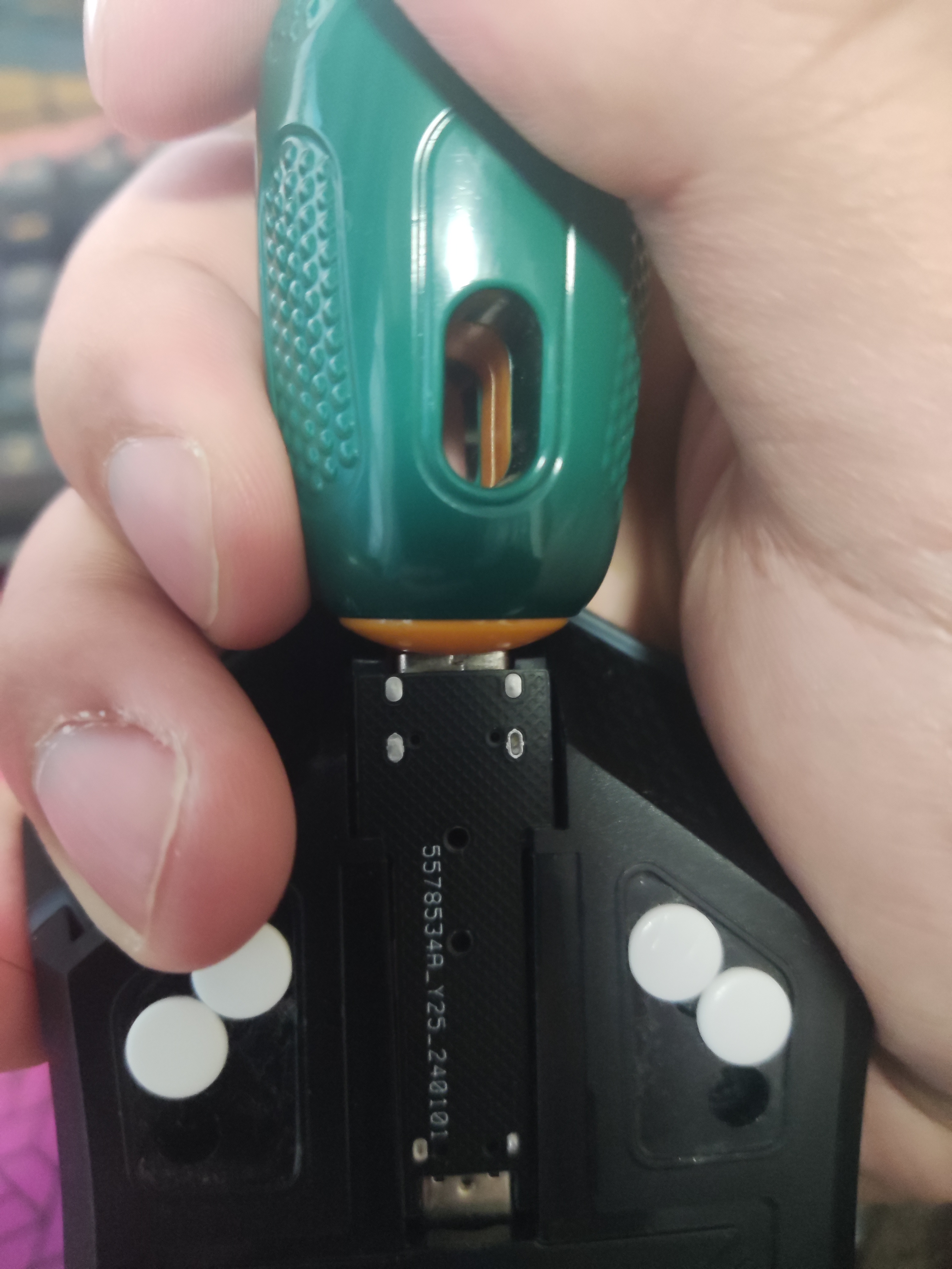
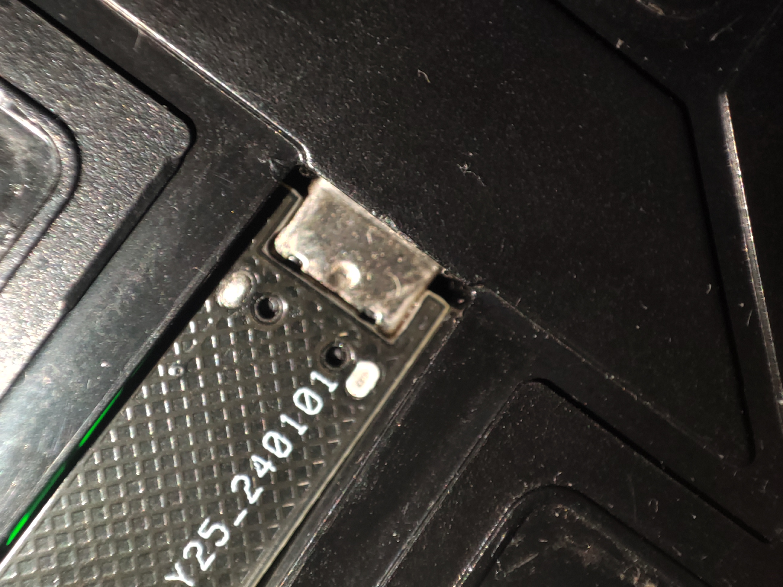
Theoretically, the adapter board should be able to be removed after insertion. There are two small holes, about 1mm in diameter, in the middle of the adapter board. I was thinking of using tweezers to push the adapter board out, but it's too tight, and I was afraid of making it difficult to push out, so I don't have a separate picture of the adapter board.
PDF_MS420DS MicroUSB to Type-C.zip
Altium_MS420DS MicroUSB to Type-C.zip
PADS_MS420DS MicroUSB to TypeC.zip
BOM_MS420DS MicroUSB to TypeC.xlsx
96392
Tuozhu LED light base charging board
This printed circuit board is designed for Tuozhu LED lights and comes with a 3D model.
This printed circuit board is designed for Tuozhu LED lights and includes a 3D model STL file.
Functions: The Tuozhu LED light base charging module provides charging, protection, and voltage boosting functions.
The positive and negative terminals of the battery icon on the PCB are connected to the positive and negative terminals of the battery. The 5V and GND outputs are silkscreened; only 5V is output, which can be connected to the positive and negative terminals of the LED. The Type-C port is the charging interface. When Type-C is connected, it powers the battery and provides power; when Type-C is not connected, the battery powers the battery.
The unsilkscreened pin headers (pins 2 and 3 of the five-pin header, i.e., the pins with copper contacts) are connected to the switch or directly short-circuited (a direct short circuit disables the switch function).
Base cover.STL
Base .STL
PDF_Tuozhu LED Light Base Charging Board.zip
Altium_Tuozhu LED light base charging board.zip
PADS_Tuozhu LED Light Base Charging Board.zip
BOM_Tuozhu LED Light Base Charging Board.xlsx
96399
Based on IR2104 bipolar SPWM inverter
SPWM single-phase inverter based on RI2104
This is a single-phase SPWM inverter based on the RI2104 microcontroller
with complementary SPWM outputs
and a 12V auxiliary power supply. The MOSFETs, inductors (2MWh), and capacitors (8UF) are
selected based on the input/output parameters.
f334c8t6_spwm.zip
PDF_Based on IR2104 Bipolar SPWM Inverter.zip
Altium-based IR2104 bipolar SPWM inverter.zip
PADS_Based on IR2104 Bipolar SPWM Inverter.zip
BOM_Based on IR2104 Bipolar SPWM Inverter.xlsx
96400
electronic


 京公网安备 11010802033920号

 164029


