This is a modification for Panda thermal imaging systems purchased in bulk by group members.
The original system does not support analog output; parameters can only be viewed and adjusted via the Ethernet port. Furthermore, connecting only the thermal imaging module will cause it to restart after a short time.
It requires modifying the motherboard firmware, removing the NAND chip, and flashing the new firmware.
The firmware can be found in the administrator's post (83L). It features
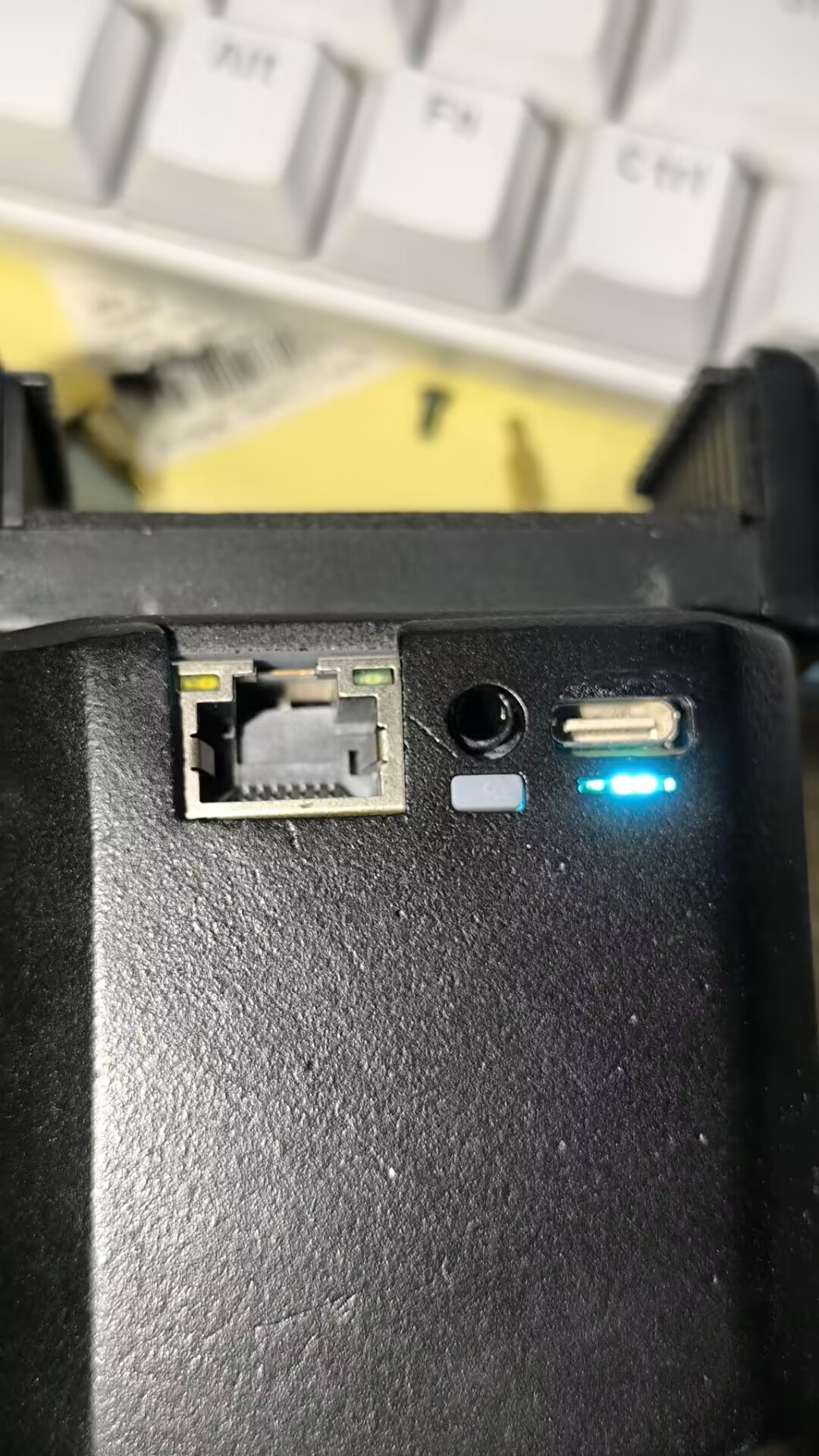
an Ethernet port, analog output, and UVC output.
It includes power management and supports 3.7V pouch batteries.
It converts analog to UVC video output, using an audio port for the analog output to reduce size. The UVC output offers multiple resolution options.
The conversion chip is MS2107, which can be purchased at https://m.tb.cn/h.5jxT7Tm?tk=kyowWWvEhWV. The chip and firmware flash together cost 25 RMB including shipping.
The Ethernet port uses a recessed design for a smaller profile.
The analog connector plugs into the 2-pin socket on the motherboard. Only four Ethernet cables and one ground cable are needed for the Ethernet port. Only the power cable is needed for the power supply. Only pins 1 and 10 are needed for the thermal imaging black cable.
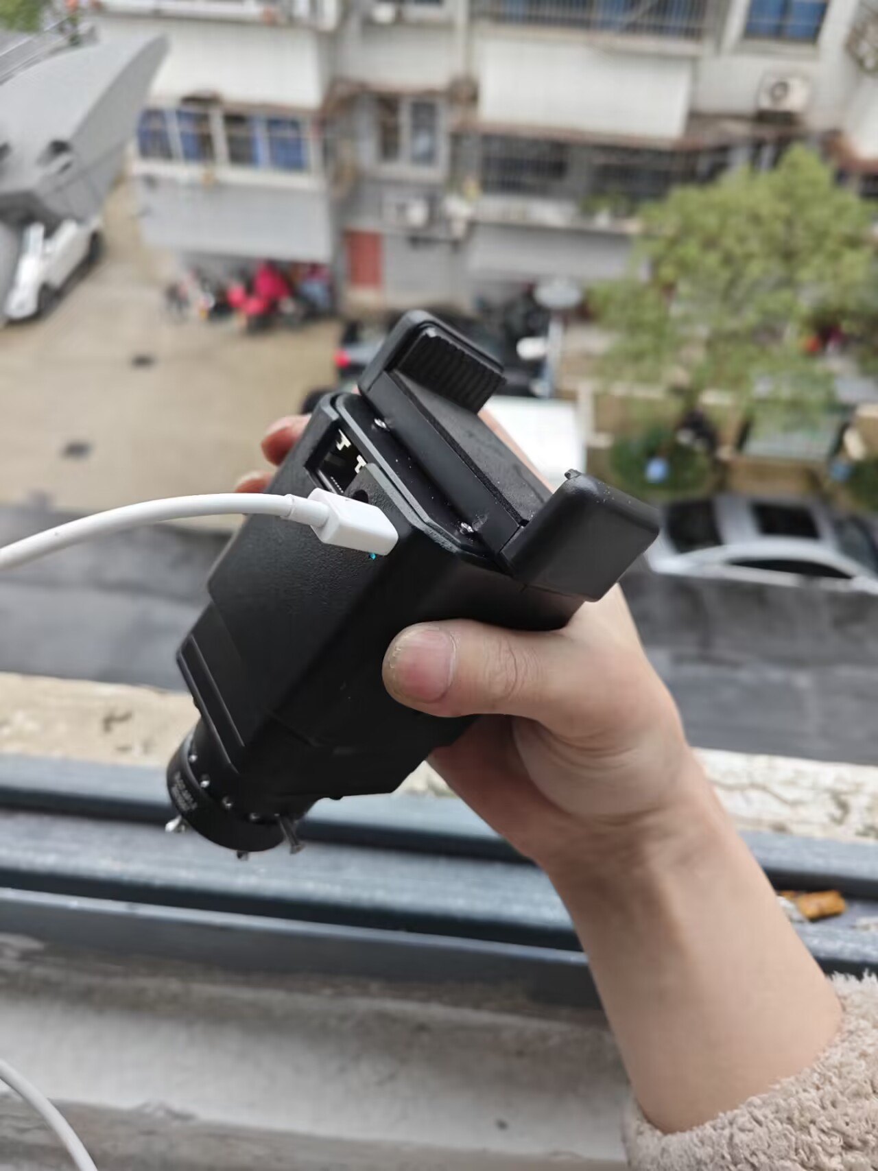
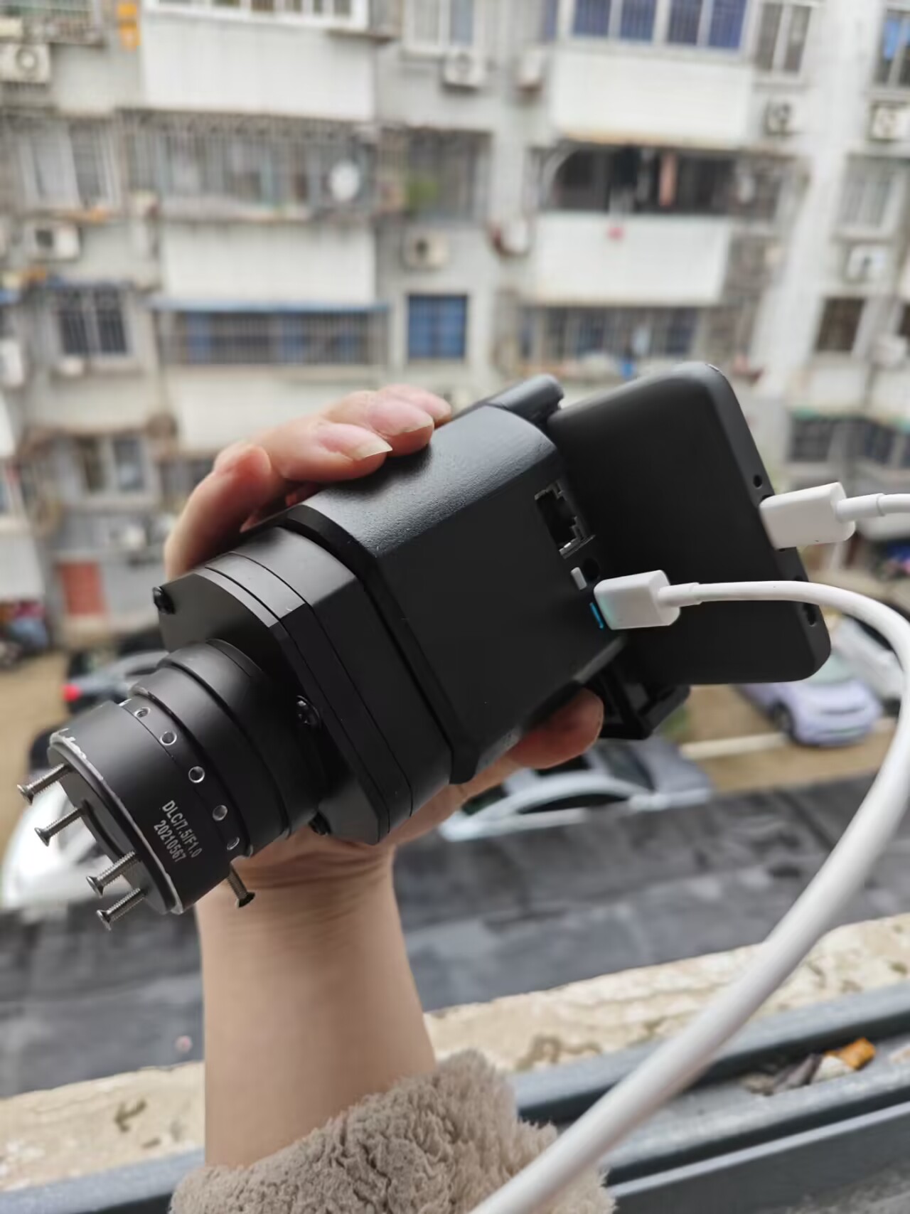
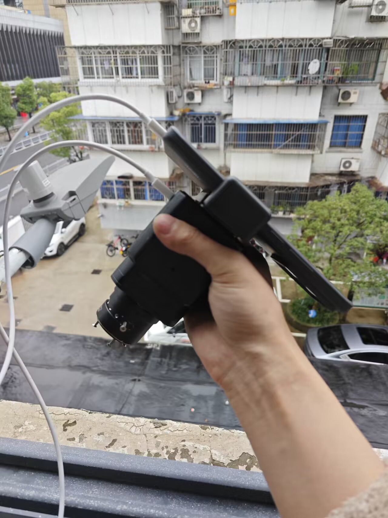
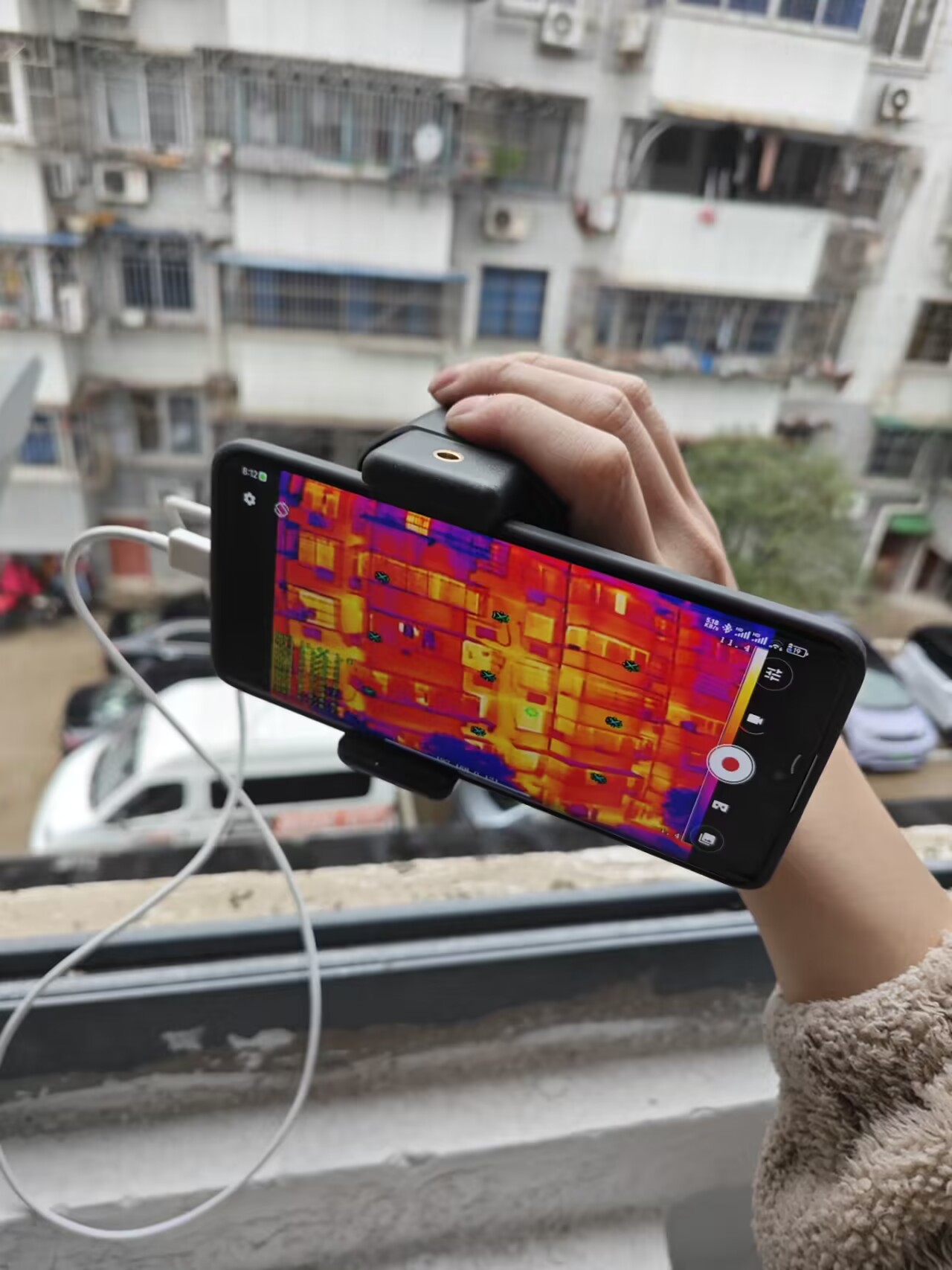
It can be handheld with the modified casing (designed by Shuangqiu).
When used with the NextCamera mobile app, it can simulate pseudo-color transitions; while not as good as native, the effect is still quite good. It also supports screen flipping and multiple resolutions.
The first version uses an IP5306 integrated power supply with a power indicator. It powers on with a button and powers off with a double-click (it automatically powers on when plugged in and cannot be powered off), requiring a relatively high current output from the phone's USB port.
The second version uses a TP4056+EC190708 with a charging indicator. It powers on/off with a 2-second long press. The capture card is entirely powered by USB; the battery only powers the thermal imaging. A new 6-12V power output has been added to the headphone jack, consistent with the thermal imaging power supply, reducing reliance on the phone's USB output current.


QQ Video 20231112201211.mp4
PDF_Mao_Panda Thermal Imaging Mod.zip
Altium_Mao_Panda Thermal Imaging Mod.zip
PADS_Mao_Panda Thermal Imaging Modified.zip
BOM_Mao_Panda Thermal Imaging Modification.xlsx
96528
Stereo to Virtual 5.1 Surround/4-to-1 Switch/Electronic Volume Control PT2322+PT2323
Stereo to virtual 5.1 surround sound solution with PT2322+PT2323 configuration + electronic 4-to-1 switcher + electronic volume control
This project (https://oshwhub.com/aknice/5.1wu-xian-huan-rao-yin-xiang) is a 5.1 wireless surround karaoke speaker system (stereo to virtual 5.1 surround/4-to-1/electronic volume control using PT2322+PT2323 ). It's a
demo board only and requires 9V power.
For actual IIC control applications and demonstration code, please refer to https://oshwhub.com/aknice/5.1wu-xian-huan-rao-yin-xiang.
PDF_Stereo to Virtual 5.1 Surround - 4-Switch 1-Electronic Volume Control PT2322+PT2323.zip
Altium Stereo to Virtual 5.1 Surround Sound Converter - 4-to-1 Electronic Volume Control PT2322+PT2323.zip
PADS_Stereo to Virtual 5.1 Surround_4-to-1_Electronic Volume Control PT2322+PT2323.zip
BOM_Stereo to Virtual 5.1 Surround_4-to-1_Electronic Volume Control PT2322+PT2323.xlsx
96531
Shanye MA-ERGW6 Vertical Mouse Replacement Board
Replacement board for the Shanye MA-ERGW6 vertical mouse, used to replace the left and right buttons, as well as the forward and back buttons.
This is a replacement board for the Shanye MA-ERGW6 vertical mouse, used to replace the left, right, forward, and back buttons. It was designed based on the original board and may require minor modifications.
PDF_Shanye Vertical Mouse MA-ERGW6 Replacement Board.zip
Altium_Mountain Industry MA-ERGW6 Vertical Mouse Replacement Board.zip
PADS_Shanye Vertical Mouse MA-ERGW6 Replacement Board.zip
BOM_Shanye Vertical Mouse MA-ERGW6 Replacement Board.xlsx
96532
Adjustable voltage regulator module
Adjustable voltage regulator module based on XL4016
Adjustable voltage regulator module based on XL4016
PDF_Adjustable Voltage Regulator Module.zip
Altium Adjustable Voltage Regulator Module.zip
PADS Adjustable Voltage Regulator Module.zip
BOM_Adjustable Voltage Regulator Module.xlsx
96533
ESP8266 Minimum System Board V3
This minimal system board is designed entirely based on the features of the ESP8266; it has a built-in 1000mAh pouch battery; it is easy to carry and debug; I also designed a 3D-printed shell for even greater ease of use.
The key features of this minimum system board are:
compatibility with I2C communication devices (such as OLED, magnetic encoders, etc.); compatibility with SPI communication devices (such as e-ink screens, OLED, TFT); compatibility with UART serial communication (such as GPS modules, communication between two ESP8266s); compatibility with WS2812 LED strips; and compatibility with ultrasonic modules. All I/O ports are brought out as pin headers, and a 3.3V to 5V switching function is added (by changing the jumper cap position).
It supports charging and program downloading via both Type-C and Android. I designed a two-stage switch: when switched to US5V, it powers the USB and charges the development board; when switched to ET5V, it powers the lithium battery (see schematic for detailed circuit diagram). All I/O ports are brought out as pin headers, and considering the different power requirements of 3.3V and 5V when connecting sensors, jumper caps are added to switch the power supply voltage. For the charging chip, I used the ET9640, which can not only charge the lithium battery but also output 5V.
PDF_ESP8266 Minimum System Board V3.zip
Altium_ESP8266 Minimum System Board V3.zip
PADS_ESP8266 Minimum System Board V3.zip
BOM_ESP8266 Minimum System Board V3.xlsx
96535
PD Adjustable Power Supply
Adjustable voltage level PD decoy, based on CH224K
This PD decoy with adjustable voltage levels, based on the CH224K, is compact and
supports 3.3V (low current), 5V, 9V, 12V, 15V, and 20V outputs. Output levels
can be selected via a DIP switch, with
an LED indicator for the output level.
Multiple connection terminals are supported,
and components can be reduced or removed as needed.

PDF_PD Adjustable Power Supply.zip
Altium_PD Adjustable Power Supply.zip
PADS_PD Adjustable Power Supply.zip
BOM_PD Adjustable Power Supply.xlsx
96536
DAPLINK to Type-C connector (for bicycle breathing light project)
Connectors for the bicycle breathing light project
Connecting the Type-C D+ and D- pins to SWD and SCK allows for the creation of a debugging interface via Type-C, suitable for debugging in narrow or inconvenient areas. (Supported for bicycle breathing light project)
Note: Board thickness 0.8-1.0mm.
Project link: https://oshwhub.com/ghgjkh/hu-xi-deng-v2
PDF_DAPLINK to Type-C Connector (for bicycle breathing light project). zip
Altium_DAPLINK to Type-C connector (for bicycle breathing light project). zip
PADS_DAPLINK to Type-C connector (for bicycle breathing light project). zip
BOM_DAPLINK to Type-C Connector (for bicycle breathing light project).xlsx
96537
electronic


 京公网安备 11010802033920号

 K4H511638D


