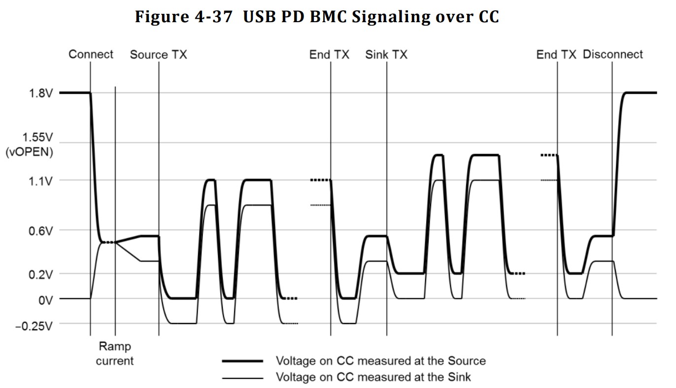
 USB PD exchanges data between the source and sink devices via the CC line in the USB Type-C connector using the BMC (Biphase Mark Code). However, the maximum communication voltage is approximately 1~1.2V, so it cannot be directly interconnected with the microcontroller's I/O ports.
  On the input side, an analog comparator compares the signal to a 0.6V reference voltage, thus converting the signal into a digital signal. The software uses a timer to measure the time difference between transitions and decodes the BMC into binary.
  After the signal is decoded from the BMC, the software looks for a preamble consisting of alternating 1s and 0s. Once the preamble ends, the software records the binary data in 5-bit groups. After the preamble ends, we check the SOP, perform 5b4b decoding, and check the CRC. If everything is normal, we parse the data packet using the USB PD protocol.
All reference designs on this site are sourced from major semiconductor manufacturers or collected online for learning and research. The copyright belongs to the semiconductor manufacturer or the original author. If you believe that the reference design of this site infringes upon your relevant rights and interests, please send us a rights notice. As a neutral platform service provider, we will take measures to delete the relevant content in accordance with relevant laws after receiving the relevant notice from the rights holder. Please send relevant notifications to email: bbs_service@eeworld.com.cn.
It is your responsibility to test the circuit yourself and determine its suitability for you. EEWorld will not be liable for direct, indirect, special, incidental, consequential or punitive damages arising from any cause or anything connected to any reference design used.
Supported by EEWorld Datasheet
EEWorld
subscription
account

EEWorld
service
account

Automotive
development
community

Robot
development
community

About Us Customer Service Contact Information Datasheet Sitemap LatestNews


Room 1530, 15th Floor, Building B,
No.18 Zhongguancun Street,
Haidian District,
Beijing, Postal Code: 100190
China
Telephone: 008610 8235 0740
 京公网安备 11010802033920号

 D1010046441%P0


