A while ago, I suddenly noticed that the price of common STM32 chips on Taobao had dropped significantly compared to last year, so I thought about building a small development board for the STM32F1. After comparing various options, I chose the RxT6 series. 64 pins is just the right amount; I initially chose the RET6. With 512KB of Flash and 64KB of RAM, it's more than enough for casual use, running FreeRTOS and U8G2 graphics. I named it "Triumph."
commonly used onboard modules: buttons, LEDs, buzzer, W25X16, and photoresistor;
commonly used onboard module interfaces: OLED (4P), TFT (8P), ESP01S, and temperature and humidity module (4P).
For the commonly used ST-LINK connectors, a horn-shaped connector is used for direct connection to this development board, eliminating the need for individual wires at the download port.
The download mode can be switched after power-on via the side-mounted button, such as the serial download mode, which can be done via the onboard USB.
note here: the pinouts of the purchased ST-LINK chips may not be identical; I encountered this problem and it confused me. The PCB connection configuration is drawn according to the ST-LINK below.
is currently at V1.2, verifying that downloading works.
model, the 10P horn-shaped connector couldn't be found with a bent one, so a physical one was used instead. The chip soldered to
the physical chip is an STM32F103RET6.
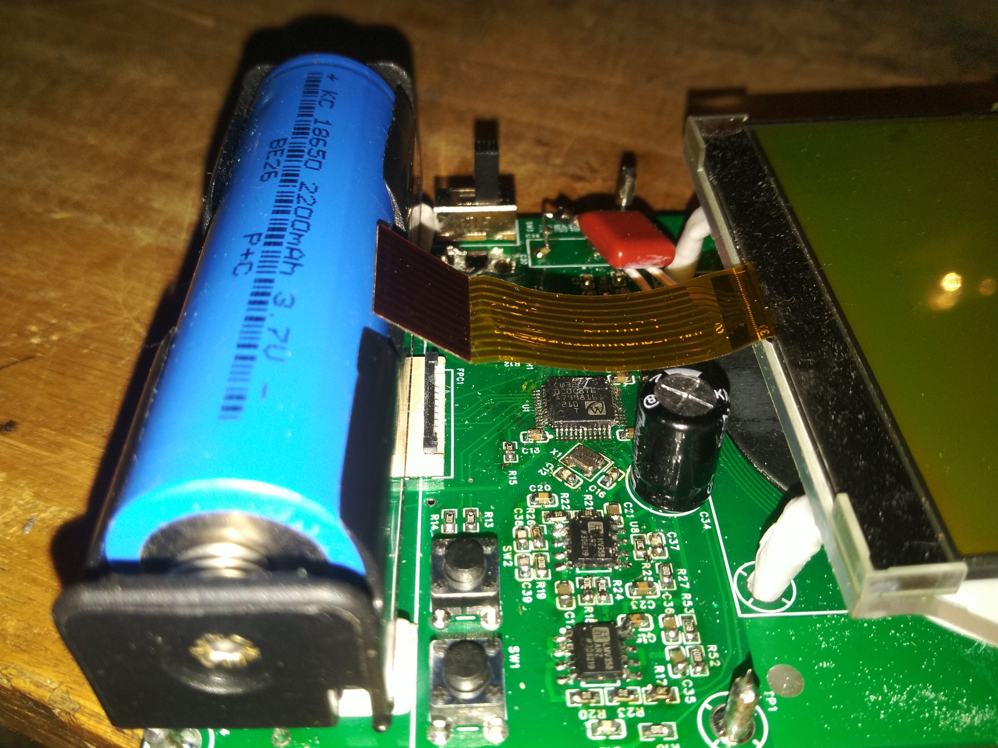
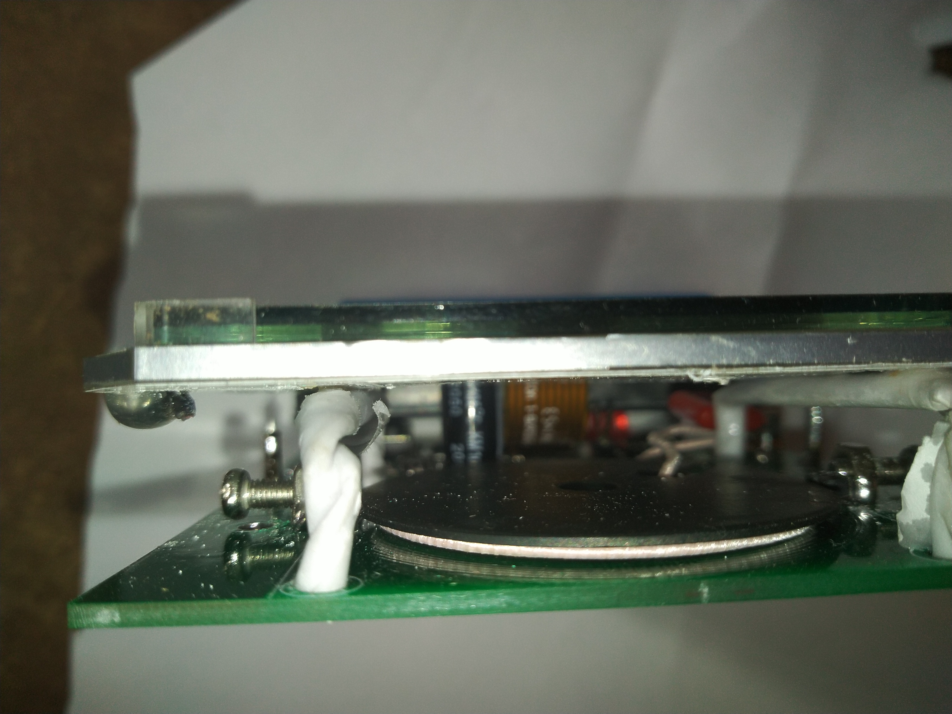
This simple wall detector was built using a CW32 microcontroller. It uses a 100kHz sine wave driven by a wireless charging coil for a mobile phone. Two semi-circular coils were drawn on the circuit board for differential input, enabling relatively accurate positioning. The maximum detection depth is 3cm with 4 square millimeter copper wire and 5cm for steel reinforcement. It is powered by a single lithium battery, resulting in low power consumption.
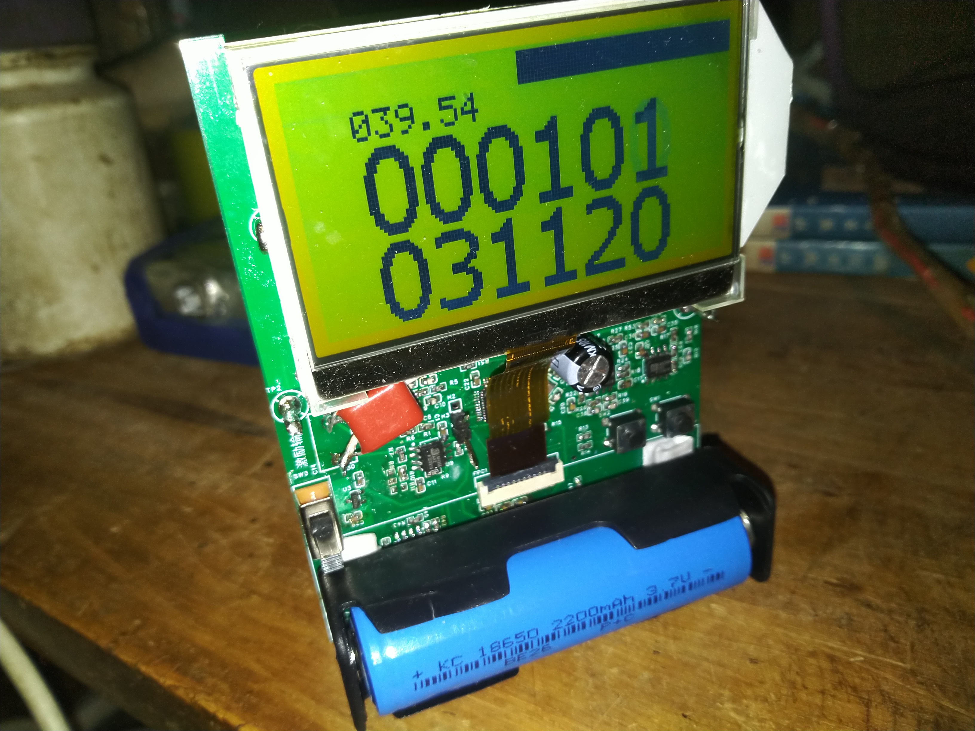
The zero point is the center of the indicator bar; crossing this point indicates the position of the wire.
Circuit principle:
A CW32F030C8T6 microcontroller is used as the main control
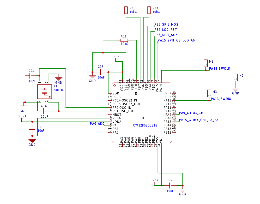
unit
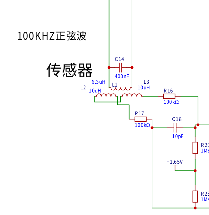
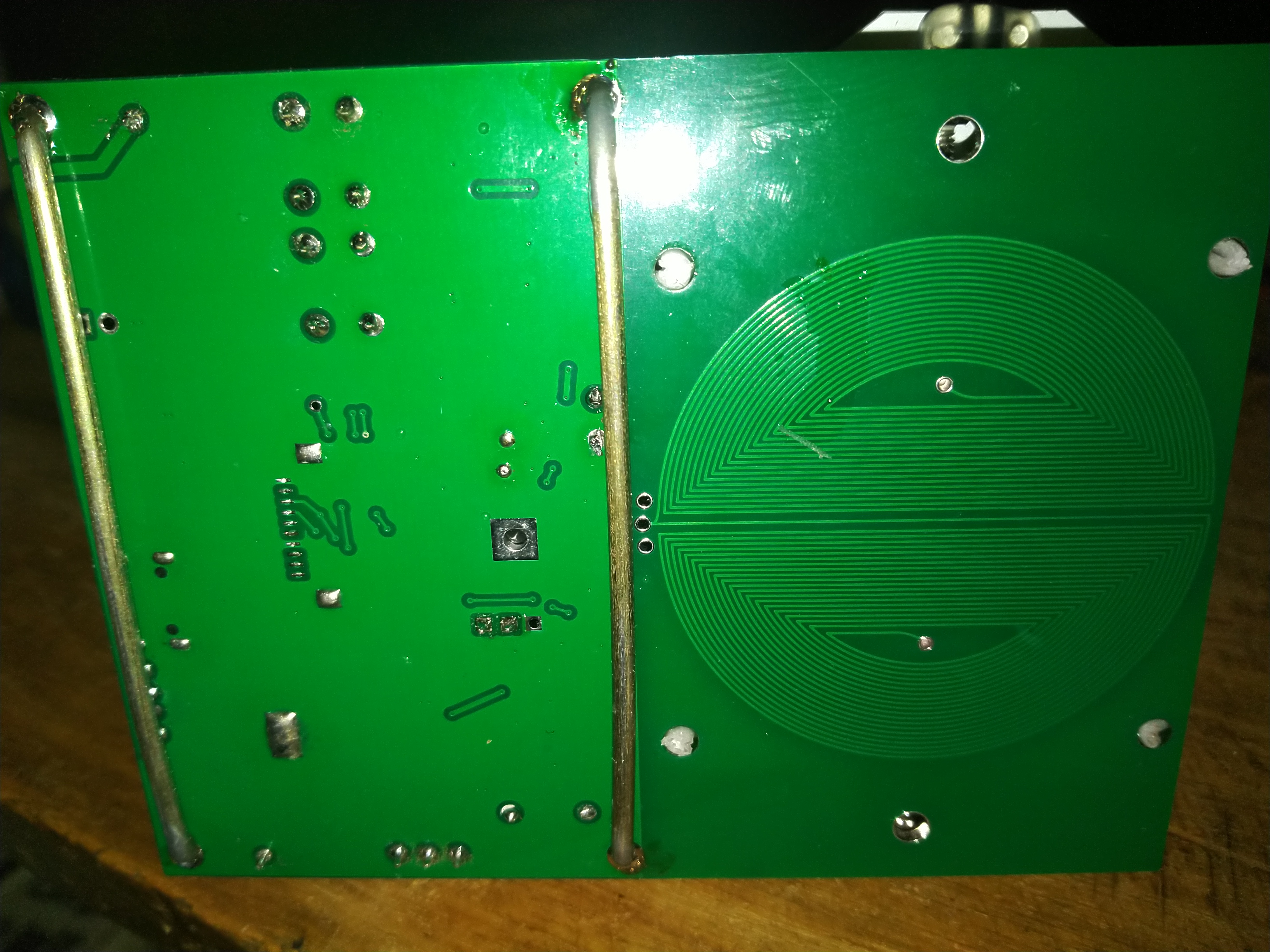
. L1 is the wireless charging coil for the mobile phone, using a 400NF CBB capacitor specifically for wireless charging. Screws are needed on both sides of the wireless charging coil for balance and fixation.

L2 is the coil excitation circuit drawn on the PCB

. The microcontroller outputs a 100kHz PWM signal, which is filtered into a sine wave by an RC filter. One operational amplifier amplifies this in-phase signal, while the other inverts it. A 104 capacitor isolates and drives the wireless charging coil.
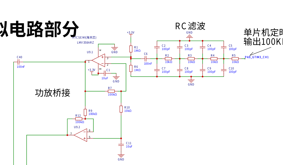
The signal amplification circuit uses a two-stage amplification. The first stage uses differential amplification. Sensitivity can be increased by adjusting R27 in the operational amplifier circuit before the ADC. Reducing the resistor can also improve sensitivity.

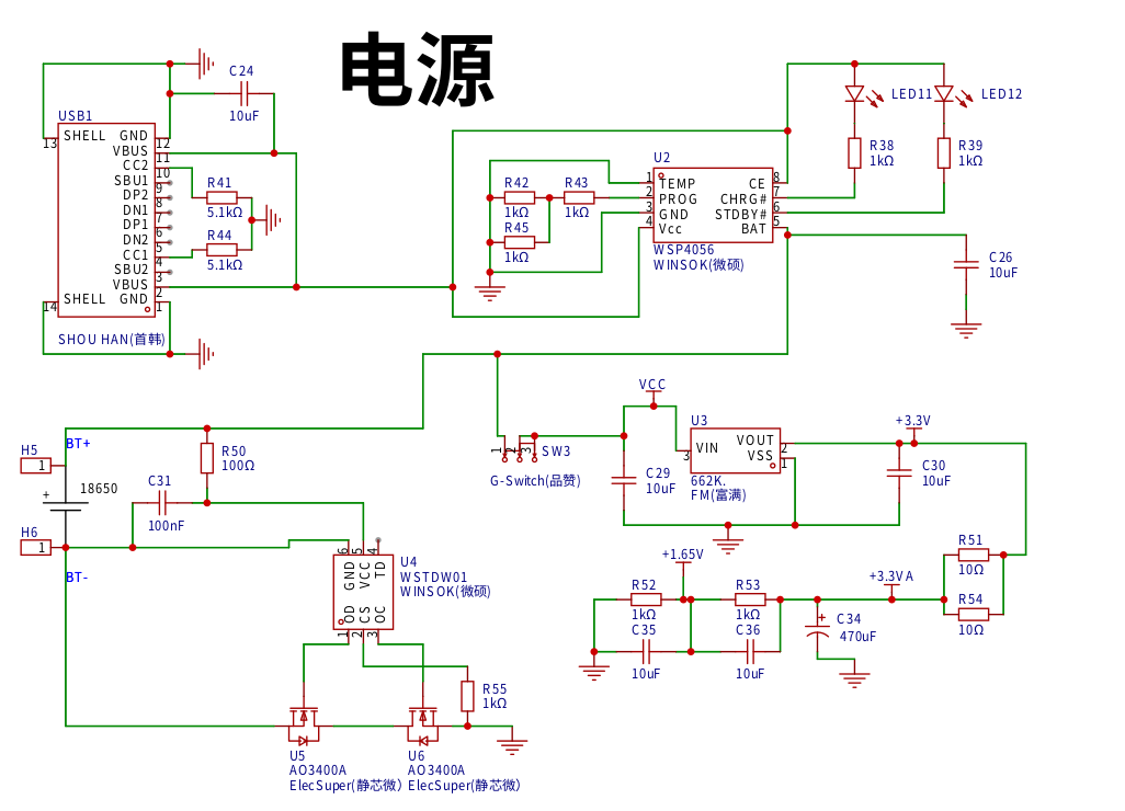
A single 18650 power supply is used.
The display uses a COG12864
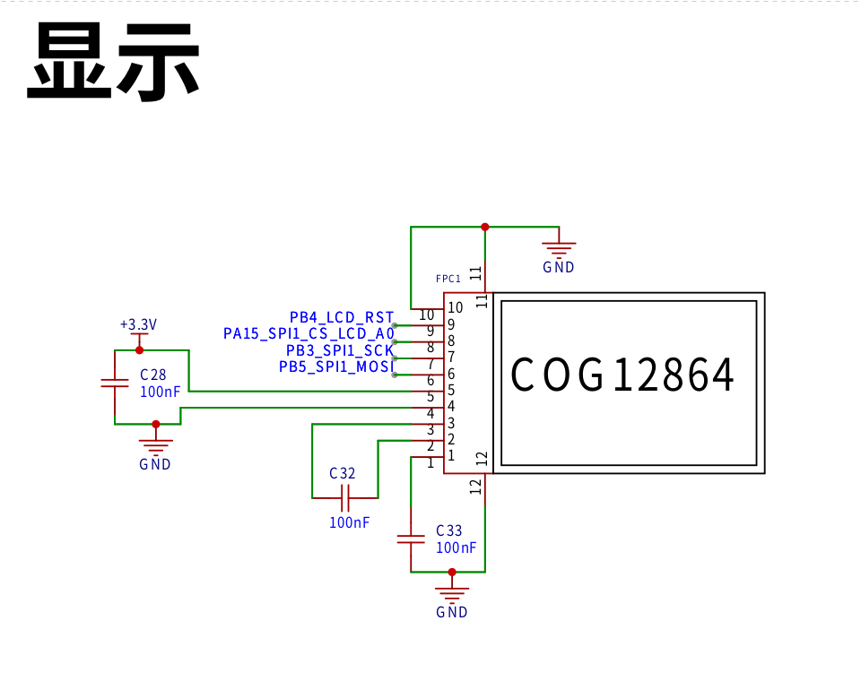
program. The program principle is: a timer outputs one 100kHz PWM channel, the ADC sampling rate is 1MHz, 2000 points are collected, and DFT demodulation is performed. 1.S is the source code, 1.bin is the firmware, and the compiler is ARM-NONE-EABI.
Debugging method: After soldering the circuit, adjust the position of the wireless charging coil to minimize the LCD reading.
The left button clears the display, and the right button restores the default settings. Press the right button first, then simultaneously press the left button to enter the speaker and progress bar sensitivity parameter settings. Press the right button to start setting, use both buttons to increase or decrease the reading, and press and hold both buttons simultaneously to save the settings. [
Image of the actual product ]

Source code and firmware.zip
Usage instructions video.mp4
Video of detecting electrical wires in my wall.mp4
PDF_Wall Detector Based on CW32 Microcontroller.zip
Altium_CW32 Microcontroller-based Wall Detector.zip
PADS_CW32 Microcontroller-Based Wall Detector.zip
BOM_Wall Detector Based on CW32 Microcontroller.xlsx
96579
80EQ electric power
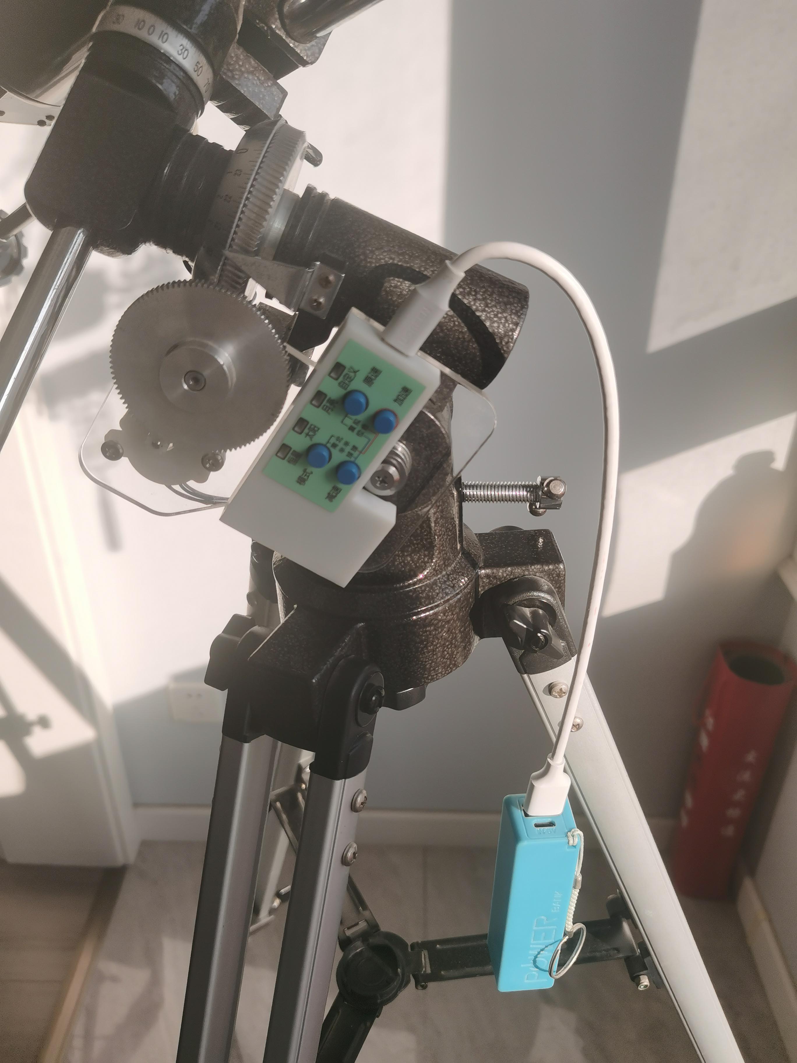
80EQ Astronomical Telescope Single-Axis Power and DIY
1. Final product photos:
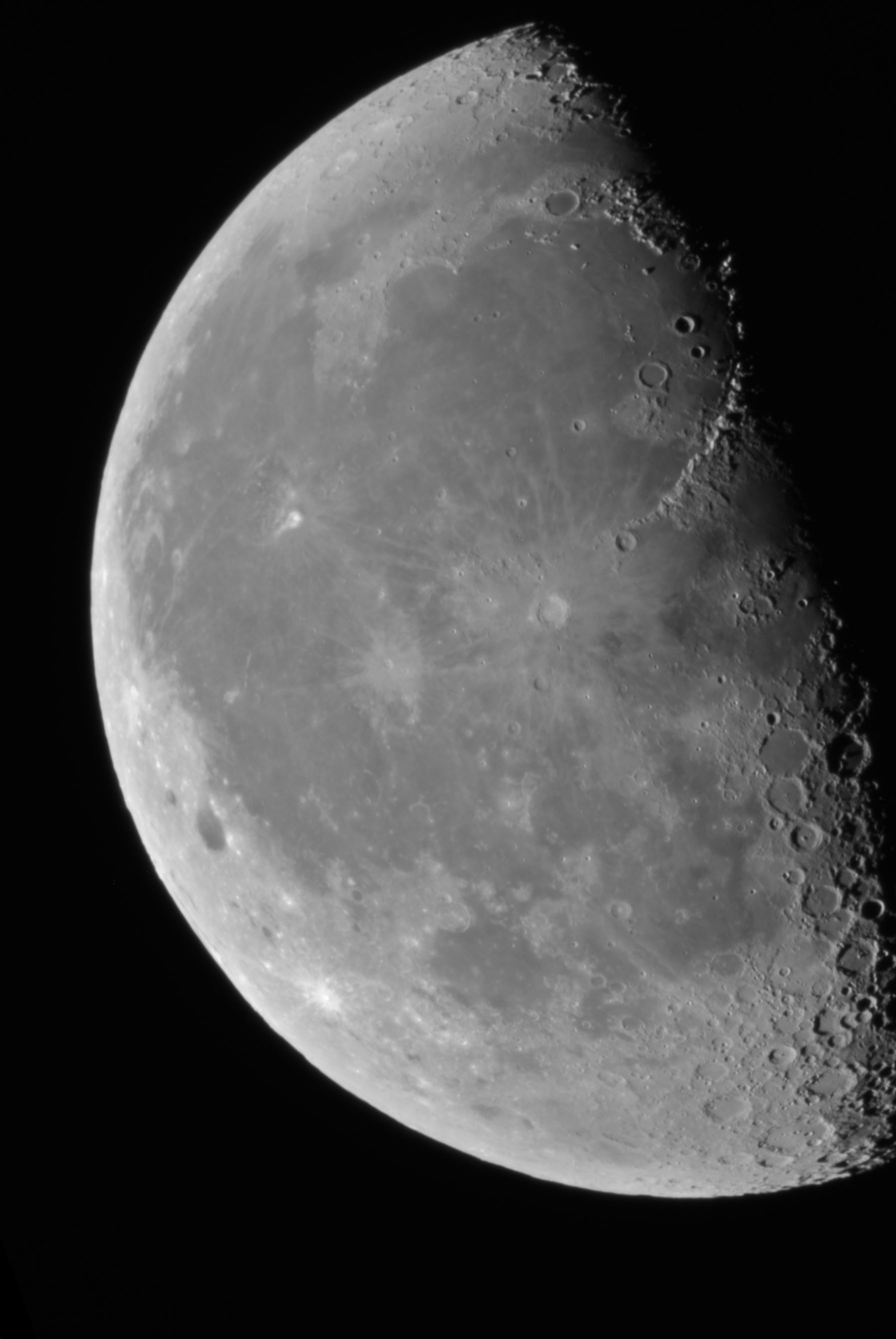
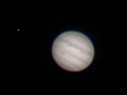
2. Photos
taken using a power supply + 80EQ + Nikon J5
: Moon:

Partial lunar eclipse:

Jupiter:
Saturn:

3. Project introduction:
Using the CH32V203 RISC-V microcontroller as the main controller (inexpensive and domestically produced);
using the RX8025 temperature-compensated clock chip as the crystal oscillator (high precision, adaptable to different temperatures, ensuring accuracy in both winter and summer);
using the TMC2226 stepper motor with 256 microsteps for high precision and quiet operation;
using the MB85RC16 ferroelectric memory to store parameters (long write life, no data loss during power loss, and fast speed).
PDF_80EQ Electric Tracker.zip
Altium_80EQ Electric Tracker.zip
PADS_80EQ Electric Tracker.zip
BOM_80EQ Electric Tracker.xlsx
96580
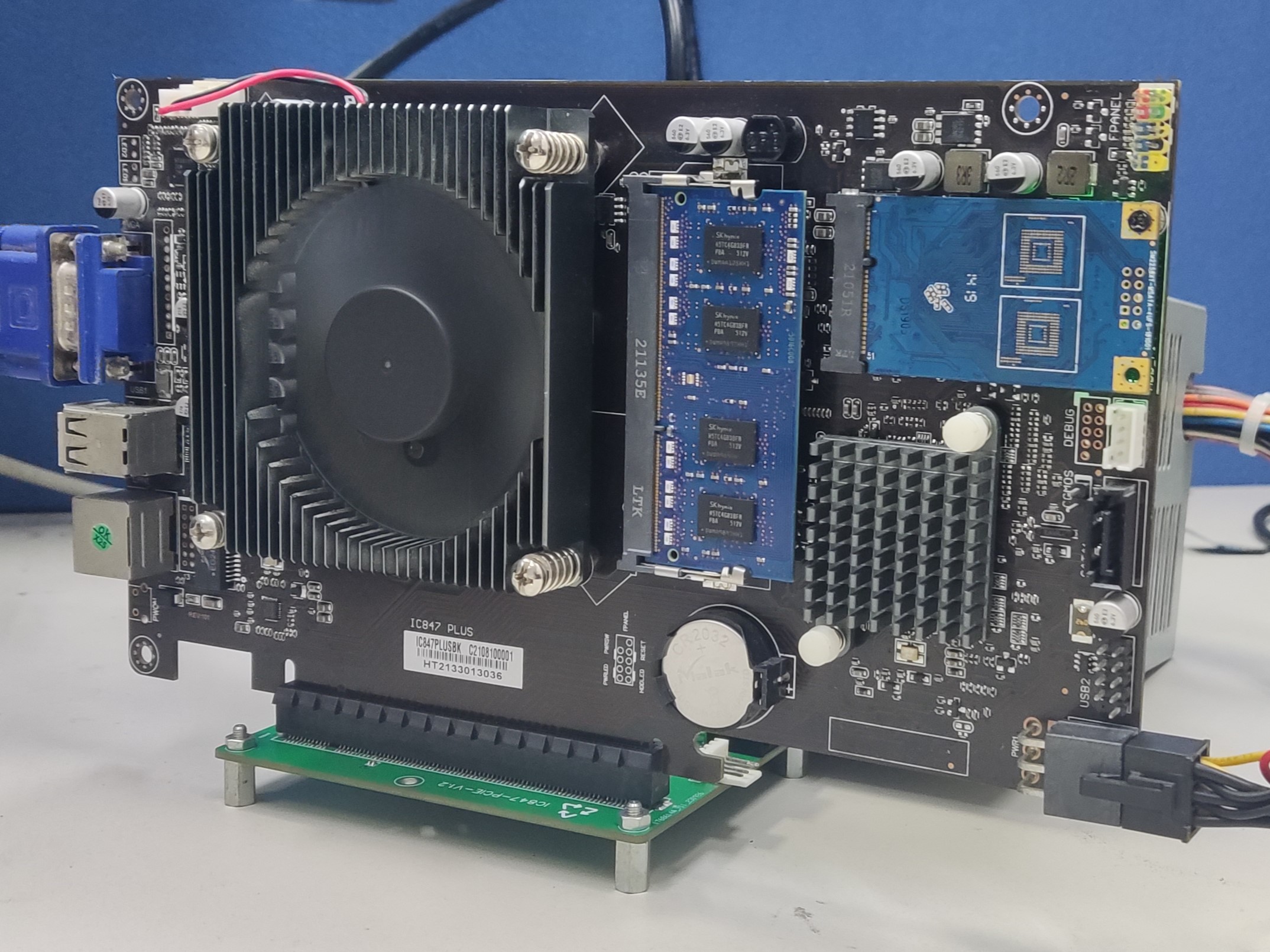
847 controller adapter board
The PCIe lanes used to bring out the 847 control board
are not supported by the gold finger power supply on my board, so the expansion board needs a separate power supply.
I'm not a professional, and as a beginner in the mechanical industry, please be gentle with your criticism. The 847 I bought doesn't seem to support baseboard power supply, so the baseboard needs to be powered. So far, I haven't encountered any problems with the small network card I plugged into the 8111F.
PDF_847 controller adapter board.zip
Altium_847 controller adapter board.zip
PADS_847 controller adapter board.zip
BOM_847 Controller Adapter Board.xlsx
96581
Debugtools
This project is a debugging tool that integrates two high-performance serial ports, a J-Link debugger, a simple logic analyzer, an adjustable voltage output of 1.8~5V, and high-precision current monitoring.
Precautions:
1. The digital board V1.0 integrates J-Link OB, and V2.0 integrates J-Link V9. Neither will lose firmware, but J-Link OB is slower. J-Link V9 cannot currently be programmed on the Nordic platform. Other platforms still need to be tested. It is supported by mainstream microcontroller platforms.
2. When the power supply is set to output below 5V, the maximum current should be kept below 1.5A for a long time, and can reach 1.9A instantaneously. When switched to 5V, it is a direct USB output, and the current limit is the output power limit.
Key Material Procurement Guide
3.0mm BTB Connector:
【Taobao】https://m.tb.cn/h.54ewsyw?tk=2MkvdBiujf6 CZ0001 "Single slot 0.5mm pitch male and female gold plated, height 3.0/5.0mm board to board BTB connector PCB socket"
Click the link to open directly or search on Taobao to open directly
2.0mm banana socket
【Taobao】https://m.tb.cn/h.5f0StZA?tk=HCg3dBiC1Pc CZ3457 "2mm banana socket pure copper gold plated K2A33 jack 2mm test hole circuit experimental teaching instrument circuit board"
Click the link to open directly or search on Taobao to open directly
e2p
【Taobao】https://m.tb.cn/h.5f07MGF?tk=PQxddBiCLaA CZ3457 "Original Huaguan AT24C02M5/TR Silkscreen 2CMU20 Package SOT-23-5 Surface Mount Chip"
Click the link to open directly or search on Taobao to open
the dial
[Taobao] https://m.tb.cn/h.5f07cei?tk=LPPFdBixPYZ CZ0001 "MITSUMI SIQ-02FVS3 Rotary Encoder with Slider 15 Positioning"
Click the link to open directly or search on Taobao to open
the screen
[Taobao] https://m.tb.cn/h.5PHgvFp?tk=YBMbW4mMAoa CZ3457 "1.14-inch LCD Screen IPS High-Definition Display 135240 Resolution ST7789 Serial Port Screen"
Click the link to open directly or search on Taobao to open directly.
The hardware and program haven't been optimized in time, so there may be some mess and bugs. Please modify it yourself; please don't criticize! Thank you!
If you have any questions, please join the group to find solutions. QQ: 865851787
**The program is too large to upload; please download the attachment from the group!**
All J-Link firmware comes from open-source developers!
PDF_Debugtools.zip
Altium_Debugtools.zip
PADS_Debugtools.zip
BOM_Debugtools.xlsx
96582
electronic
 Verification
  the 3D
  the physical chip is an STM32F103RET6.
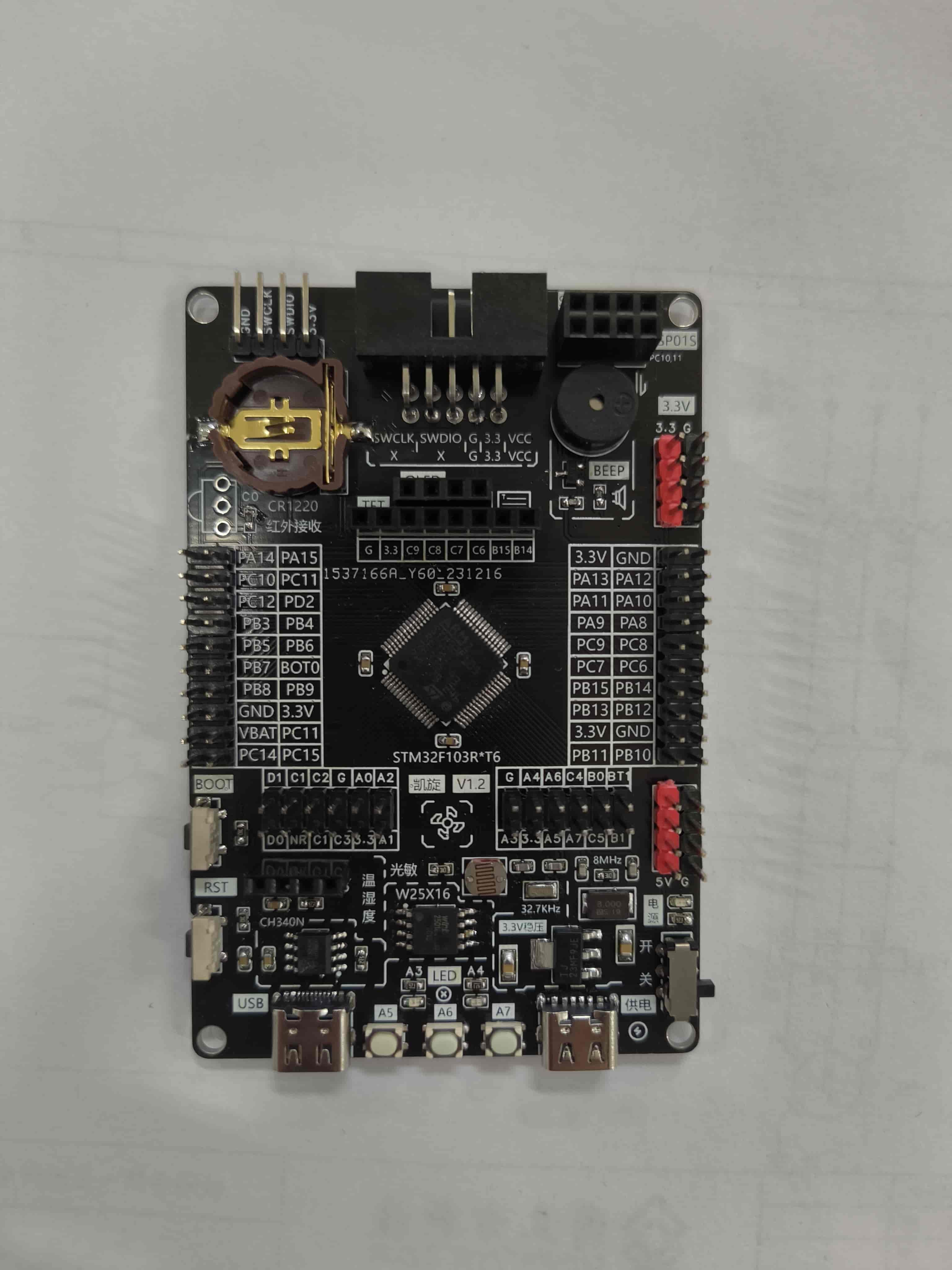


 京公网安备 11010802033920号

 2200AAG300222SA


