This module is for use with a 14-pin ASUS SPI TPM connector header. Please check the motherboard manual to confirm that the interface and the header header interface definition in the diagram below are consistent.
The size is 1.6cm x 1cm, and the height depends on the header header and the thickness of the board you purchase.
This module uses Infineon SLB 9670VQ2.0, QFN package. Discarded chips from Taobao cost 5 yuan each. The header
header has a 2mm spacing. For the 2*7-pin surface mount header header,
you will also need one 1uF and two 100nF 0603 package surface mount capacitors.
The top left and bottom right are two 0Ω 0603 package resistors, as specified in the chip datasheet. They can be connected together with a lump of solder.
I used an ASUS TUF GAMING B550M-PLUS motherboard, and it worked.
Note that if the chip model is different, please refer to the specific chip datasheet to check if it can be used on this board
. Regarding soldering, I connected the ground to the middle heatsink pad, and drilled four holes in the heatsink pad to connect to the 14-pin connector on the back. I'm unsure if it's a manufacturing issue or a design flaw on my part, but with QFN-packaged chips, the solder mask between the chip pin interface pads and the heatsink pads is easily burned off by the soldering iron, causing solder to flow onto the heatsink pads and preventing the chip pins from receiving solder. Therefore, I recommend using solder paste and a hot air gun to solder the chips, ideally achieving a successful solder joint on the first attempt to avoid solder mask detachment.
Regarding the 14-pin female header, if your purchased header doesn't have keyed connectors, please carefully insert it into the motherboard according to the motherboard manual. I am not responsible for any damage caused by incorrect insertion that results in chip burnout or even motherboard damage.

PDF_TPM_2.0_moudel.zip
Altium_TPM_2.0_moudel.zip
PADS_TPM_2.0_moudel.zip
BOM_TPM_2.0_moudel.xlsx
94887
Preamplifier boost circuit based on SG3525
Introduction: This project is a pre-amplifier boost circuit based on the SG3525, which uses a transformer to boost the 12V voltage to 400V. The SG3525 PWM wave drives two sets of MOSFETs, enabling the transformer to operate in push-pull mode. This board is the pre-amplifier board for a subsequent 220V pure sine wave inverter.
1. Design Task and Requirements
1.1 Design Background
With the development of the economy and society, the demand for energy is increasing. The scarcity of oil resources and their rising prices, as well as the environmental pollution caused by traditional energy use, have led people to turn to the development of clean energy (domestic abundant solar/wind energy). The inverter is a key component of the entire solar/wind energy system, which can convert the variable DC output obtained from solar/wind energy into a clean sinusoidal 50 or 60Hz current, thereby meeting our needs for the indispensable 220V AC power in the daily environment. As a college student, I hope there are any unreasonable or immature aspects in the design, and I welcome everyone's corrections so that we can improve together.
1.2 Design Requirements
1. Able to boost 12V DC to 400V with auxiliary power supply.
2. Normal no-load power consumption and stable operation of the switching transistor.
3. Short circuit and overcurrent protection.
4. High flexibility and simple and direct circuit structure.
1.3 Design Task
First, high frequency. Increasing the switching frequency of the inverter can effectively reduce the size and weight of the device, and at the same time eliminate the audio noise of the transformer and inductor. While improving the dynamic response capability of the output voltage, the size and weight of the device are also reduced. Second, high performance. It is required to have good voltage regulation performance, and the effective value of the output voltage must be stable under no-load and load conditions; in addition, the waveform quality is also required to be high. The transient response characteristic of the output voltage under sudden load increase or decrease must be good. Third, parallel connection and modularization. Modern inverters are developing towards high power and reliability, so modularization is necessary to improve the reliability of the system.
2. Schematic Design Section
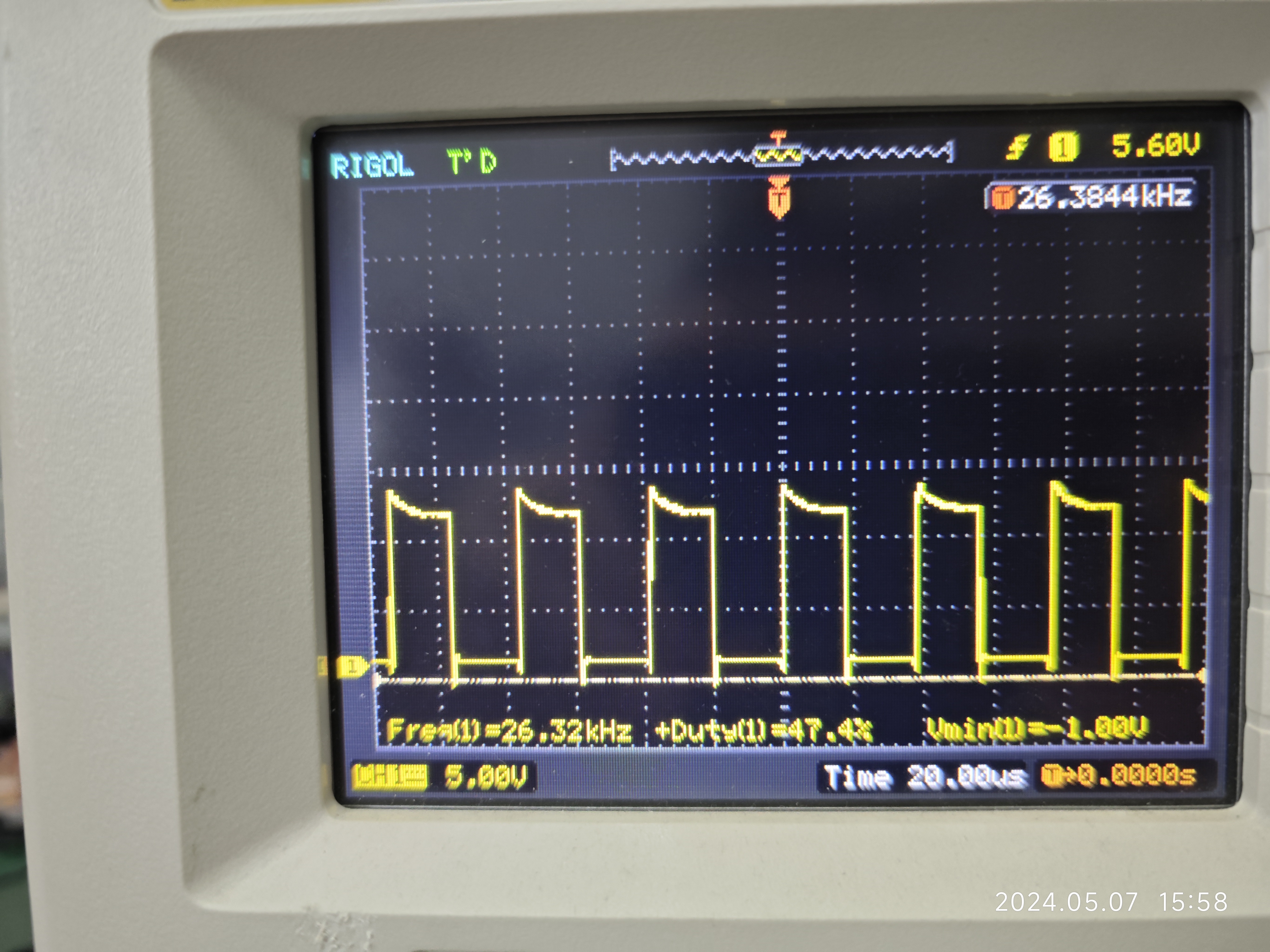
1. Principle of the Pre-amplifier SG3525 Driver Board The DC-DC driver chip used is SG3525. I will not go into details about the specifics of this chip. Its peripheral circuit can be built according to the typical application in the PDF. When the oscillation element Rt=15k and Ct=222,
the oscillation frequency is about 26.6KHz. I prefer to use a frequency of about 20KHz, which has low switching losses and low pressure on the rectifier tube, which is conducive to improving efficiency. However, the low frequency is not conducive to the miniaturization of devices, and
the high-voltage DC ripple is slightly larger, but this is not a major issue. The protection circuits are all conventional circuits built with comparators. Optical isolation is used, and the input and output of the front stage are electrically isolated. This design is also for safety.
I_BACK is an overcurrent protection circuit. The SG3525 has a built-in dead-time control and soft-start protection.
Below is the schematic diagram of the DC-DC drive circuit.

2. Schematic diagram of the front stage DC-DC power main board The DC-DC power main board uses a conventional push-pull design. Each of the four power transistors has its own gate drive resistor, and each of the four power transistors is driven by a totem. The secondary high-voltage winding of the transformer is rectified and filtered to obtain a DC high voltage. The auxiliary winding is rectified, filtered, and regulated to supply power to the 431 used for feedback in the subsequent stage.
As can be seen from the schematic diagram, a voltage conversion circuit is used to power the front stage drive board. When the input is 12V, in order to ensure that the switching transistors work normally when the power supply voltage is high, when the input is 24V, an LM2596 is used to reduce it to 15V. Regarding the selection of power transistors for the preamplifier driver transformer, the recommended voltage rating is 2.4 times the highest input voltage.
For example, for a 12V machine, the maximum input voltage is 14.5V, so 14.5V * 2.4 = 34.8V. Therefore, a 35V MOSFET can be selected for a 12V machine. However, this selection is conditional: the transformer winding process cannot be too poor, and the leakage inductance and distributed parameters cannot be too high; otherwise, the MOSFET will be damaged by the voltage spikes generated by the transformer.
If the transformer winding is good, a lower voltage transistor can be selected. Generally, for the same current, a higher voltage transistor has a larger input capacitance and higher internal resistance. But if the transformer winding is poor, choose a higher voltage MOSFET. The primary stage uses two pairs of STB15810s from STMicroelectronics, with a VDSS of 100V and an IDS of 110A, which is perfectly adequate.
The transistors I used are not the most suitable, but they are ones I have used and have had no problems. Below is the schematic diagram of the DC-DC boost converter preamplifier.

3. The DC-DC power mainboard schematic
is quite simple. You only need to pay attention to whether the diode's operating frequency meets the requirements, whether the filter capacitor's withstand voltage meets the requirements, and the selection of the 431 detection voltage. These will not be elaborated upon here.
Below is the schematic of the DC-DC boost board's power stage.

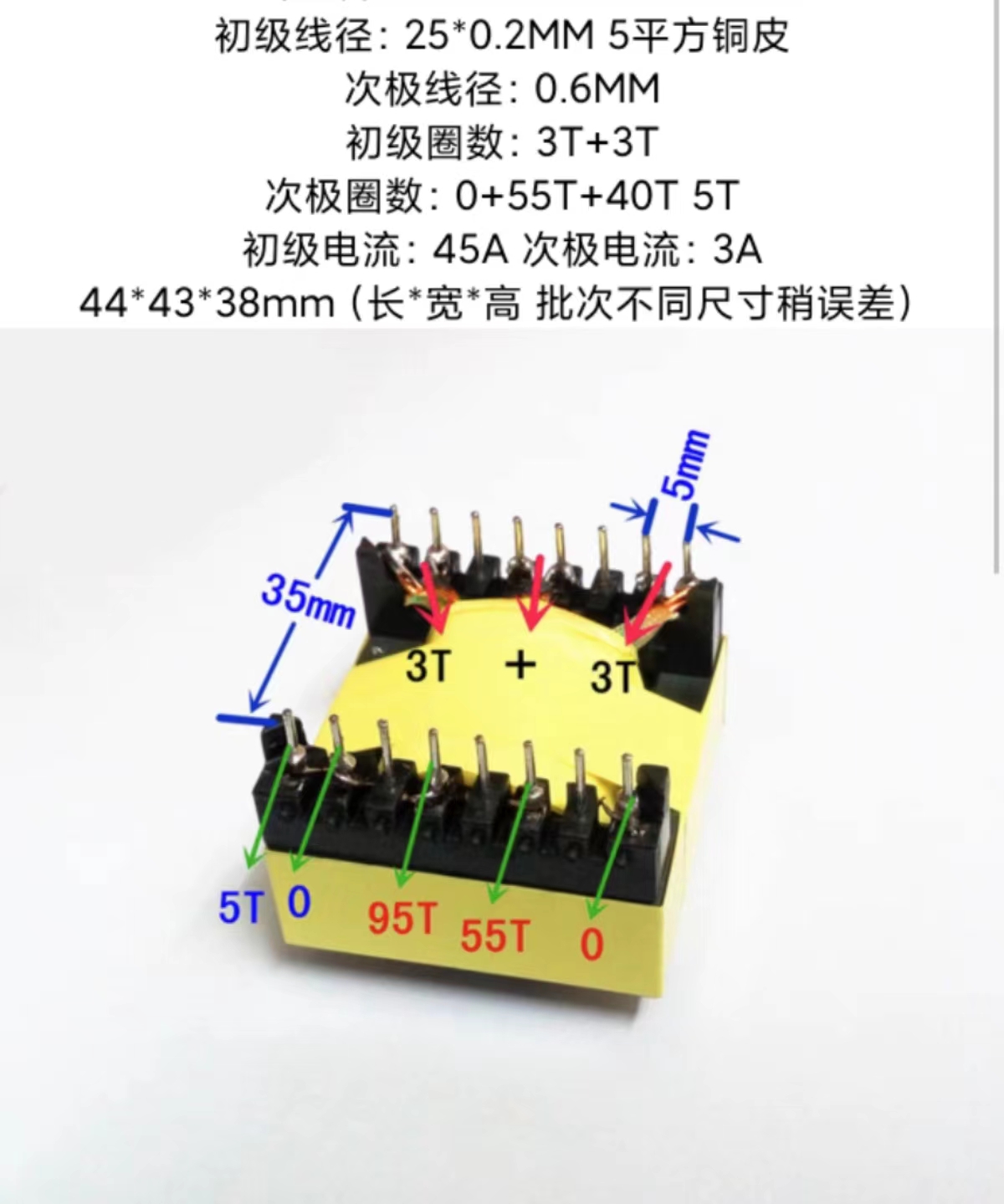
3. Regarding transformer selection and design : For
12V input, the primary winding is 2T+2T, with 14 strands of 1.0 enameled wire wound in parallel on one side, achieving a cross-sectional area of 11*2=22 square millimeters, which is sufficient for 100A current. The secondary winding is 60T wound with one strand of 1.0 enameled wire, and the auxiliary winding is 4T wound with 0.8 enameled wire. The transformer uses a sandwich winding method, i.e., secondary, primary, secondary, auxiliary. For 24V input, use an EE55 transformer, with a primary winding of 4T+4T, with 8 strands of 1.0 wire wound in parallel on one side. The secondary winding is 60T wound with one strand of 1.0 enameled wire, and the auxiliary winding is 4T wound with 0.8 enameled wire. For a 36V input, use an EE55 transformer. The primary winding is 6T+6T, with 8 strands of 1.0mm² wire wound in parallel on one side. The secondary winding is 60T wound with 2 strands of 0.9mm² enameled wire, and the auxiliary winding is 4T wound with 0.8mm² enameled wire. For a 48V input, use an EE55 transformer. The primary winding is 8T+8T, with 8 strands of 1.0mm² wire wound in parallel on one side. The secondary winding is 60T wound with 2 strands of 1.0mm² enameled wire, and the auxiliary winding is 4T wound with 0.8mm² enameled wire.
I don't have the winding equipment or tools; I bought a ready-made transformer from Taobao. If anyone wants one, please contact me for the link.
My transformer is the EC42-15; the parameters are provided below.
4. PCB Design:
1. When designing the SG3525 driver board PCB
, pay attention to the feedback resistor and place the filter capacitors nearby. The op-amp feedback
section can be designed as a restricted area to avoid oscillation. Finally, ensure the silkscreen is neatly arranged.
The SG3525 driver board PCB diagram is attached below.

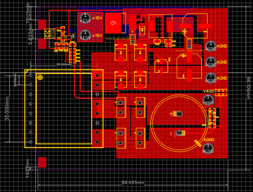
3. For the preamplifier DC-DC power mainboard PCB
, pay attention to the main current path. The power path should be clean and unobstructed. Use large areas of copper on the main path. When two main return paths are connected, place more vias. Since LCSC supports a free board area of 10*10, we chose to board two boards here for free panelization, haha.

3. For the power amplifier DC-DC power mainboard PCB,
the PCB design concept is the same as the preamplifier. Pay attention to the main current path. The power path should be clean and unobstructed. Use large areas of copper on the main path. When two main return paths are connected, place more vias.
5. Debugging section
This is the gate (G) waveform of the MOSFET. This isn't how it appears on the PCB; it's the waveform emitted by the driver board, and it's not very clear. I think it can be corrected using a digital chip or comparator.
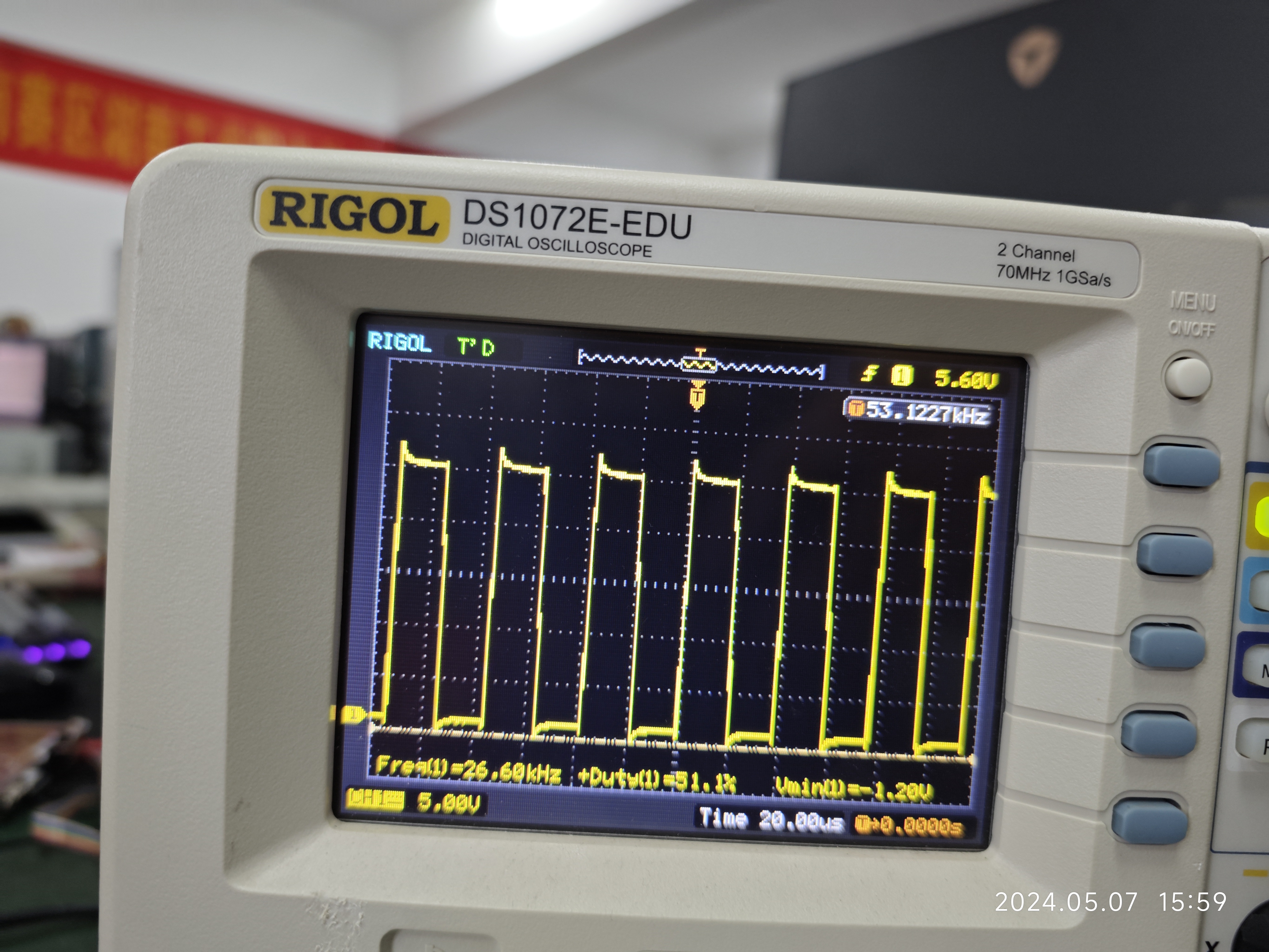
This is the source (S) waveform of the MOSFET.
The input voltage under no-load
conditions

, the output voltage of the main winding, and the output voltage of the auxiliary winding are shown here. This is the output voltage of the LM2596; the output voltage of the auxiliary winding is 19V.
Finally, here are some PCB images of
the SG3525 driver board

boost converter,

along with a working video.
May 8 (1).mp4
PDF_SG3525-based preamplifier boost circuit.zip
Altium_SG3525-based preamplifier boost circuit.zip
PADS_SG3525-based preamplifier boost circuit.zip
BOM_SG3525-based pre-amplifier boost circuit.xlsx
94888
DAP Downloader
DAP debugger made using color silkscreen printing
The debugger
is based on the ARM open-source DAP project (https://github.com/ARMmbed/DAPLink).
Hardware Overview:
The main controller uses an STM32F103C8T6.
The USB interface uses Type-C with an external current-limiting fuse and reverse connection protection diode.
The 5V to 3.3V converter uses an SOT-23 packaged LDO, which can provide a large current.
Since the JTAG interface is not commonly used, it is not yet supported.
The SWD interface and USB to TTL function have been tested.
The hardware interface definitions differ slightly from the official documentation, so it has been forked and modified: https://github.com/AFunnyMan/DAPLink_V1.
Usage:
Use the SWD interface provided with the DAP debugger to download the bootloader. After successful download, a USB drive will appear.
Drag the app into the USB drive. Wait a moment. If successful, a DAP-Link USB drive and a serial port
upgrade app will appear. Connect RST and GND, restart DAP, and a USB drive will appear. Drag the new version of the app into the USB drive to complete the upgrade.
The attached
stm32f103xb_bl.axf is the bootloader. You can use tools such as STM32 ST-LINK Utility or STM32CubeProgrammer to directly download
stm32f103xb_stm32f746zg_if.bin as the app and drag it directly into the USB drive.
stm32f103xb_bl.axf
stm32f103xb_stm32f746zg_if.bin
PDF_DAP Downloader.zip
Altium_DAP downloader.zip
PADS_DAP Downloader.zip
BOM_DAP Downloader.xlsx
94889
MOJO Power Module
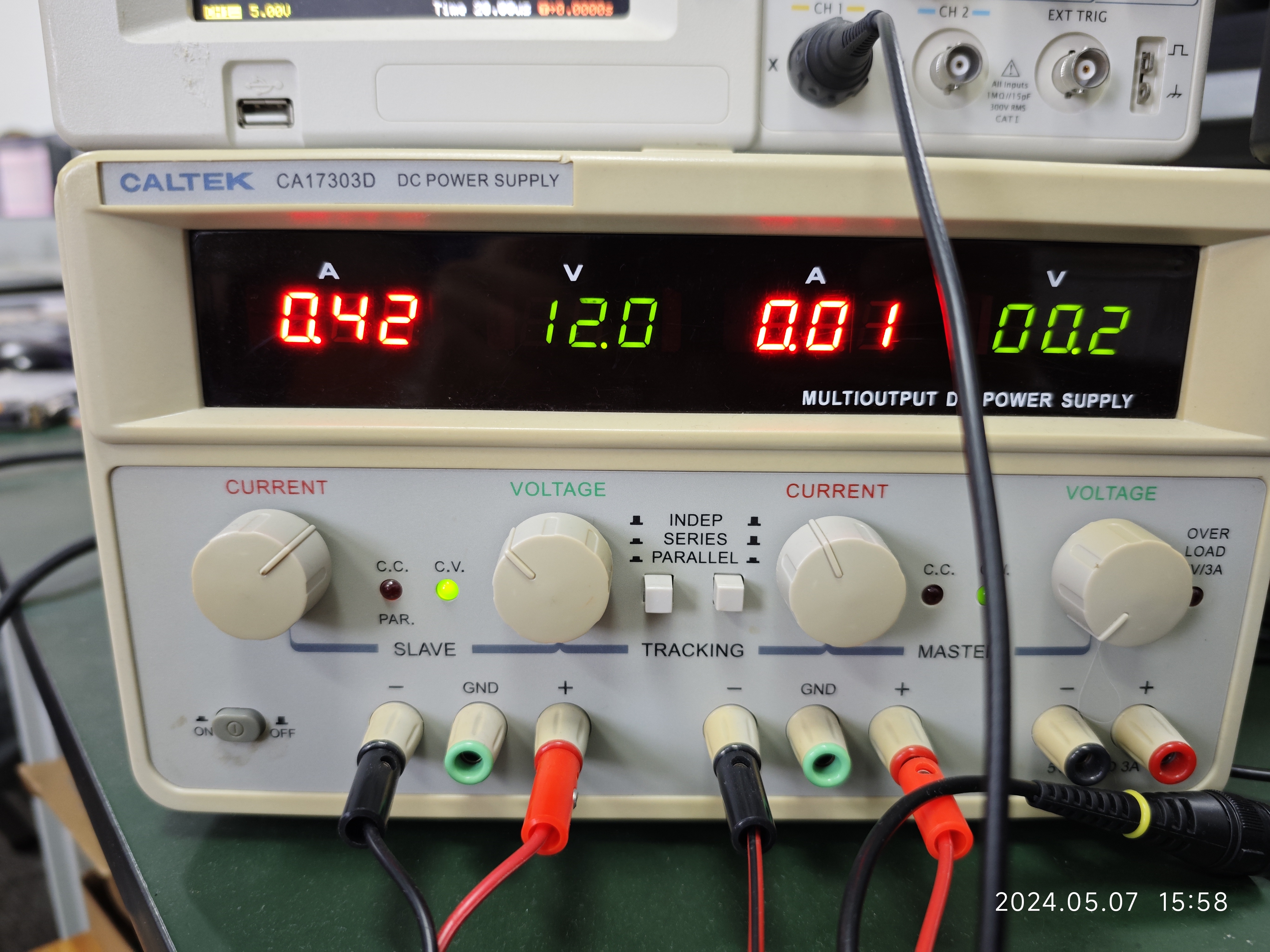
Connect the MOJO to PD power and discard the battery. Add USB isolation and power isolation.
I've been dissatisfied with the battery life and charging speed of the MOJO since I got it. I modified the DC power supply. Later, I saw a solution posted by UP: 啊猫啊狗晒太阳 on Bilibili (video address: https://b23.tv/6zgnzuz), which inspired me. I added USB isolation, power isolation, and PD decoy to the original solution, changed the TYPE-C interface, and used an AT32 MCU based on what I had.
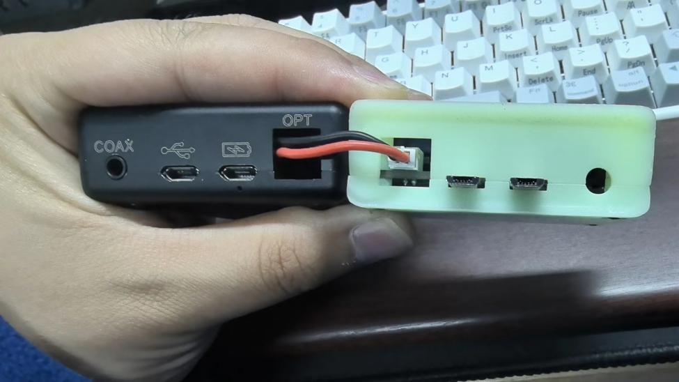
So far, it's working fine. However, adding USB isolation doesn't completely solve the USB interference problem, which is probably an issue with the MOJO itself. At least the interference from the input source is gone now. Another issue is that the MOJO automatically powers on when the capacitor is charging after powering on. If the data USB cable is plugged in at this time, it will power off because the MOJO requires a large instantaneous current when powering on and connecting the USB driver, and the capacitor cannot provide enough current when it is not fully charged. Therefore, it is recommended to wait for the capacitor to fully charge before plugging in the data USB cable. (There is a solution: add a switch to the capacitor output terminal.) My MOJO's fiber optic port was removed because I previously modified the DC power supply, and it needs to be removed again for this modification.
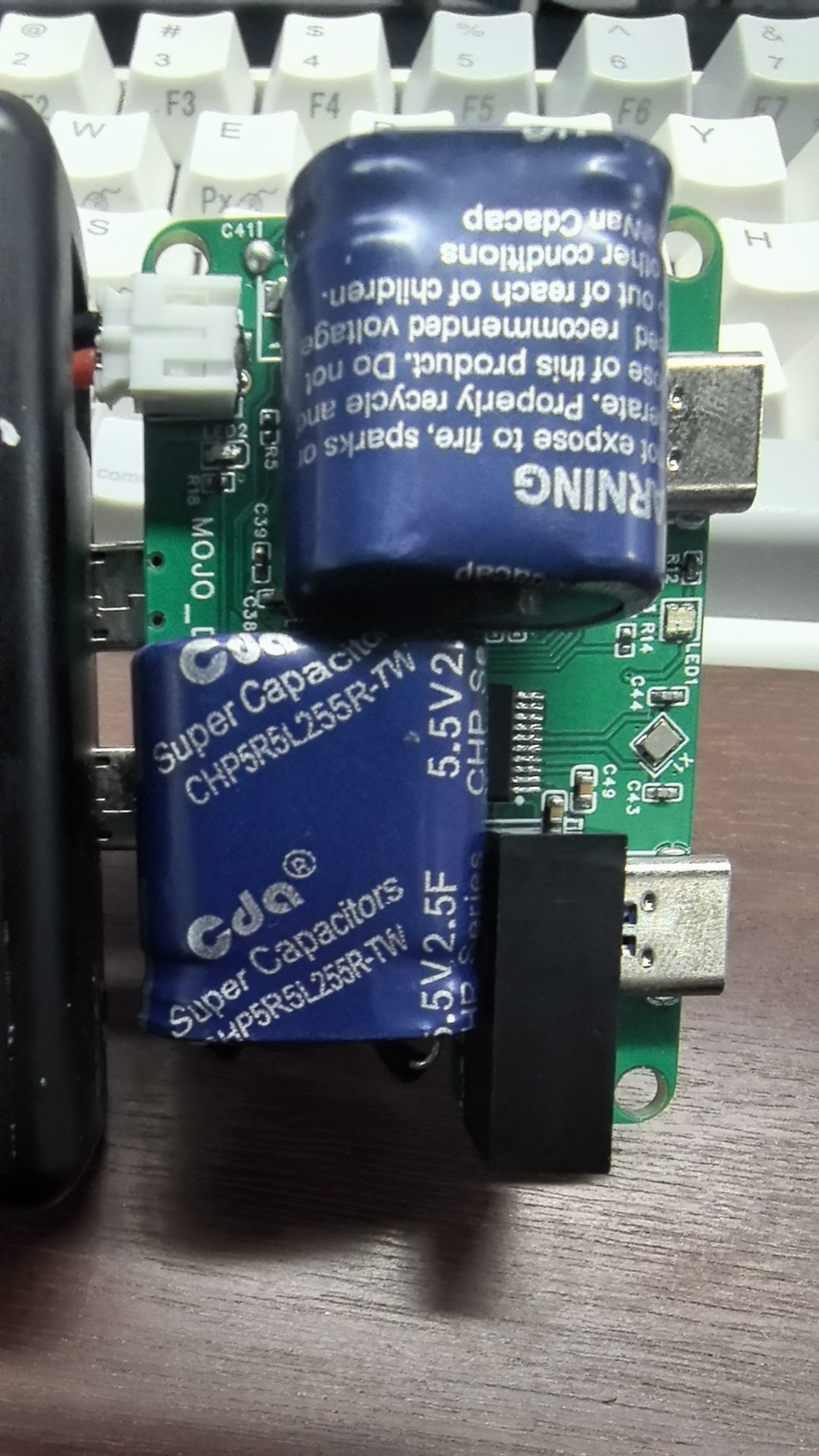
Soldering is generally not difficult; the main challenge is raising the microUSB connector to be level with the PCB. Also, be careful with the supercapacitor package; this package is only for display purposes, and you need to bend the leads when soldering the supercapacitor.

The casing is just a rough sketch; no holes are cut for the LEDs.
Main lighting effects:
LED1:
Red: Power-on input voltage error
; Yellow: Charging;
Green: Charging complete ; Yellow
-Blue: Input voltage less than 8V ; Red -Blue: Input
voltage greater than 20.5V ; Red- Green-Blue: Output voltage greater than 8.4V. LED2: Green: CH224K reaches set voltage.
Top cover .STL
Bottom cover .STL
mojo_dock.hex
PDF_MOJO Power Module.zip
Altium_MOJO power module.zip
PADS_MOJO Power Module.zip
BOM_MOJO Power Module.xlsx
94890
Esp8266 Weather Clock_2023_V0.1
The ESP8266 is an Arduino-based weather clock that can obtain the current city's weather information based on the IP's city location.
It contains firmware for DH11 to obtain the current ambient temperature and humidity
: http://bin.bemfa.com/b/3BcYTA5ZGJlNGU1OWRiNDY1Nzk0ODk0ZjQ1NDA5OWViNWY=8266Weather.bin
PDF_Esp8266 Weather Clock_2023_V0.1.zip
Altium_Esp8266 Weather Clock_2023_V0.1.zip
PADS_Esp8266 Weather Clock_2023_V0.1.zip
BOM_Esp8266 Weather Clock_2023_V0.1.xlsx
94893
electronic


 京公网安备 11010802033920号

 DLBM-CF121-MT00


