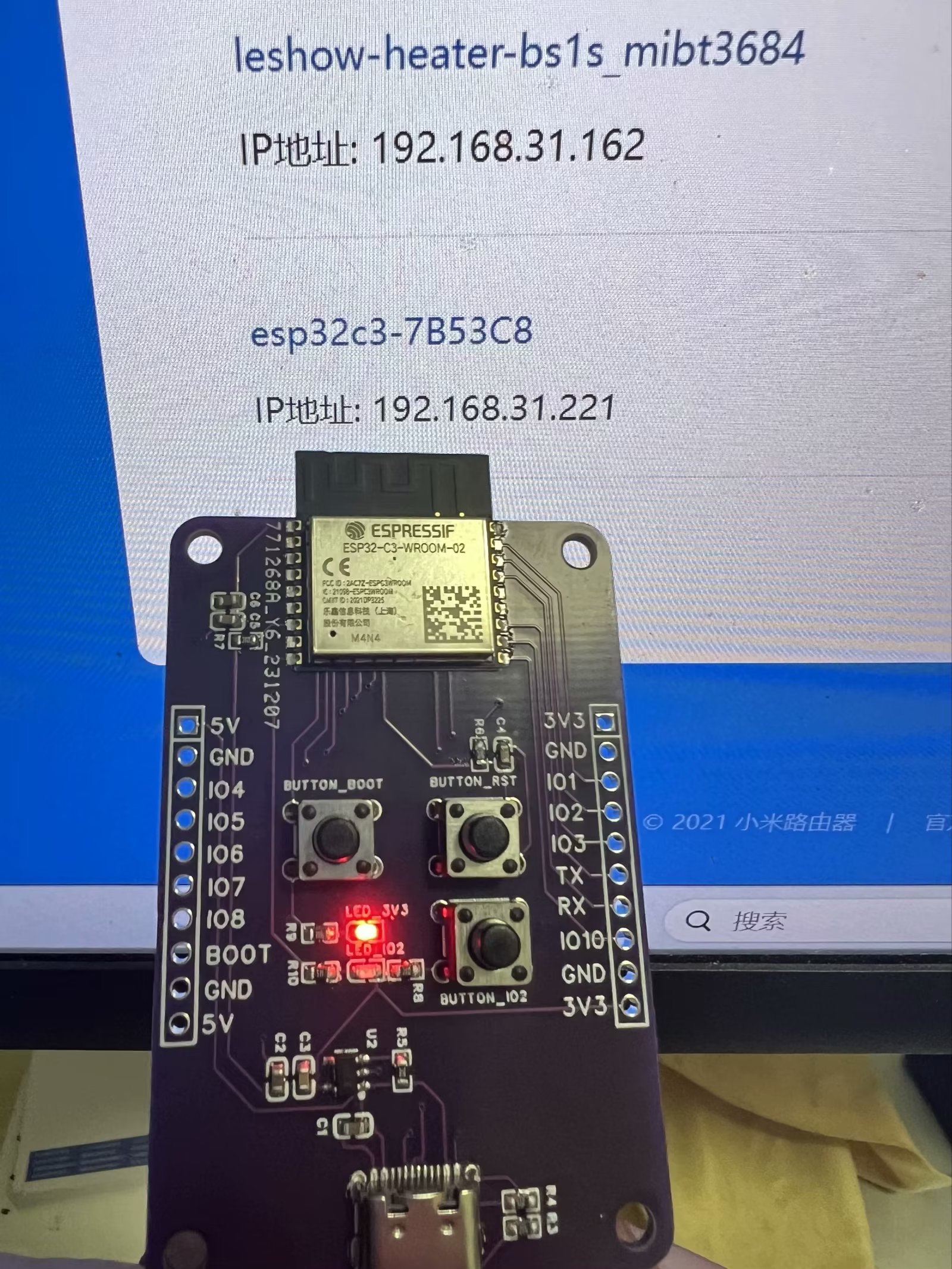
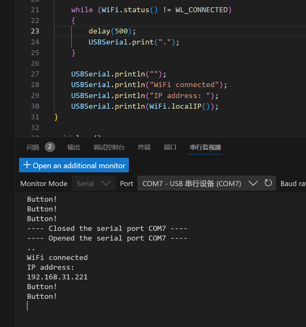
1. Automatically display temperature values and update them automatically based on actual temperature changes. 2. Implement a simulated air conditioner on/off control function, meaning the air conditioner turns on when the temperature exceeds a certain threshold and turns off when it falls below that threshold. The air conditioner's on/off control is simulated using an LED light; for example, when the air conditioner is on, a specific LED light will illuminate.
Since I am left-handed and love mouse side buttons, and there weren't any satisfactory products on the market, I decided to make one myself.
Essentially, it integrates a USB docking station, SD card reader, mouse, and STM32F103CBT6 as a USB device onto a single board.
I took two mice from a school's cleanup project and found the circuit remarkably simple. The optical encoder has built-in USB communication capabilities, and the lens can be used directly, which sparked this idea.
The casing is still under design (I'm new to 3D modeling). This post is just for verification.
For the mouse, I researched for a long time and finally settled on the Inster A704E, which can be bought directly on Taobao. It has built-in USB encoding and supports forward/backward navigation, a one-click return to desktop, and a "fire" button that allows continuous left-clicking. The circuit design is very simple.
The second idea is to integrate a card reader. Anyway, in my project... Since wired mice require carrying a USB drive to copy data during class, integrating the mouse directly into the mouse is preferable. It doesn't take up much space; the space in front of the thumb is just right.
As for the side buttons, I want to make them replaceable modules. I'm currently working on a 32-bit project, which can emulate USB devices, so I'll integrate them directly. This will only occupy one USB port and can be expanded via the side panel to create a matrix of side buttons.
It can also connect to a joystick, trackball, knob, etc., providing more interaction methods. The SL2.1a provides four USB 2.0 ports; my previous device used three, leaving one to connect to a 2.4GHz transmitter for a wireless keyboard, hidden inside the mouse.
Testing showed the design is flawless, except the card reader gets quite hot.
Areas for optimization: Currently, the 32-bit component can only be programmed externally; I plan to research a solution for remapping the buttons on a host computer in the next step.
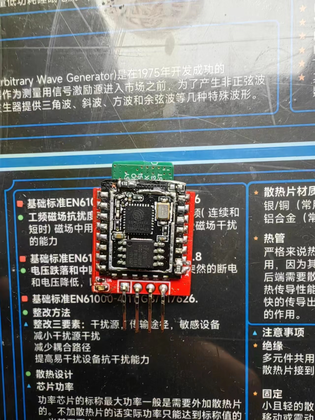
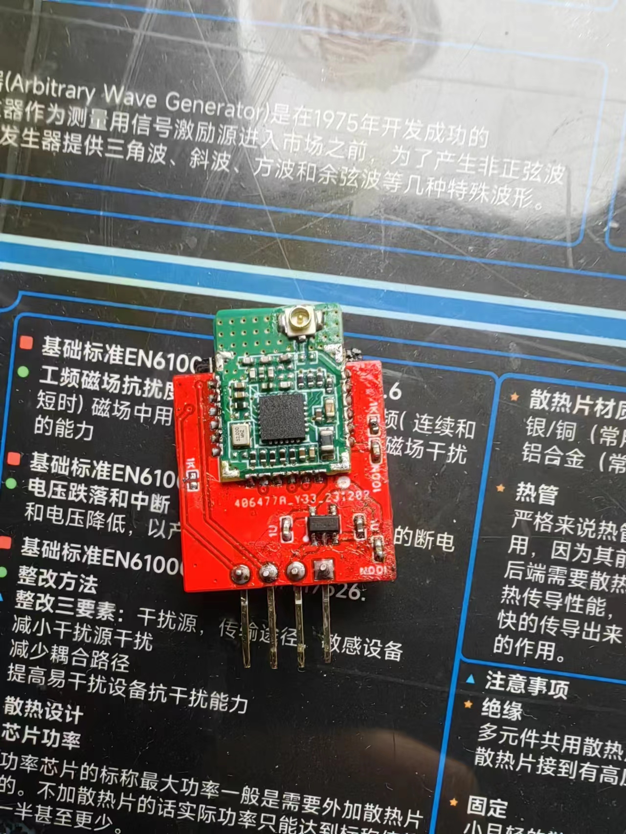
Minimize the size of the ELRS receiver by using the A28+8266 solution.
ELRS, a low-cost receiver built using the A28 and ESP_12F.
Flashed with the official Betafpv Nano RX firmware.
See details: https://www.bilibili.com/video/BV1Uu4y1t7Fk/
Many people said the previous version was too large, so this is a smaller and lighter version.
PDF_elrs_8266_rx_mini.zip
Altium_elrs_8266_rx_mini.zip
PADS_elrs_8266_rx_mini.zip
BOM_elrs_8266_rx_mini.xlsx
96802
[2023 Electronic Engineering Contest] Problem E - Experimental Platform
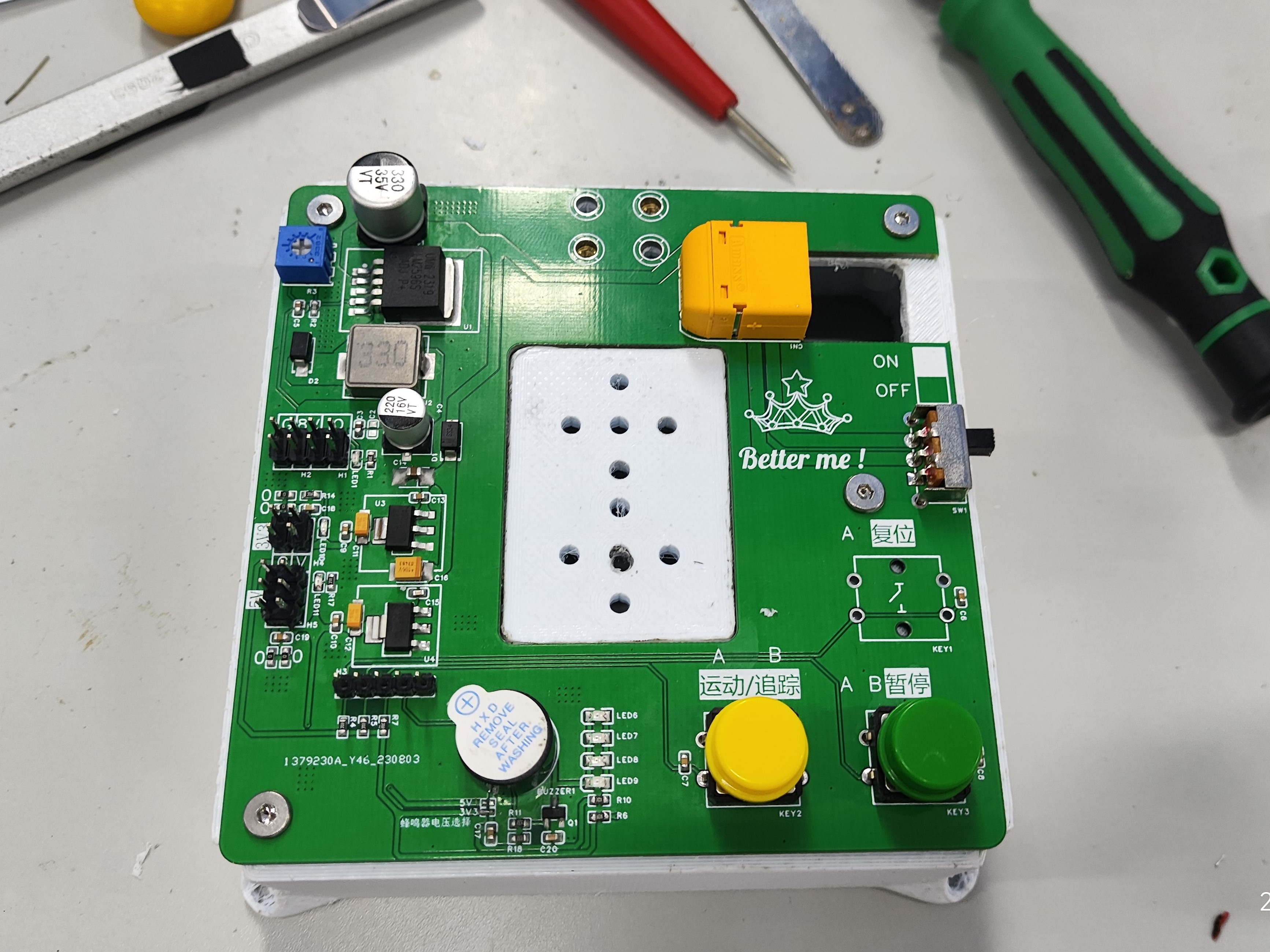
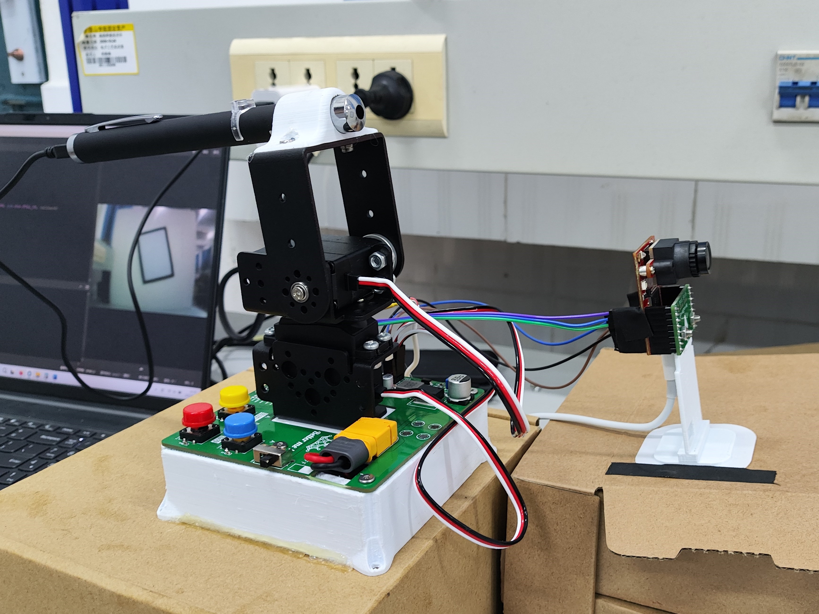
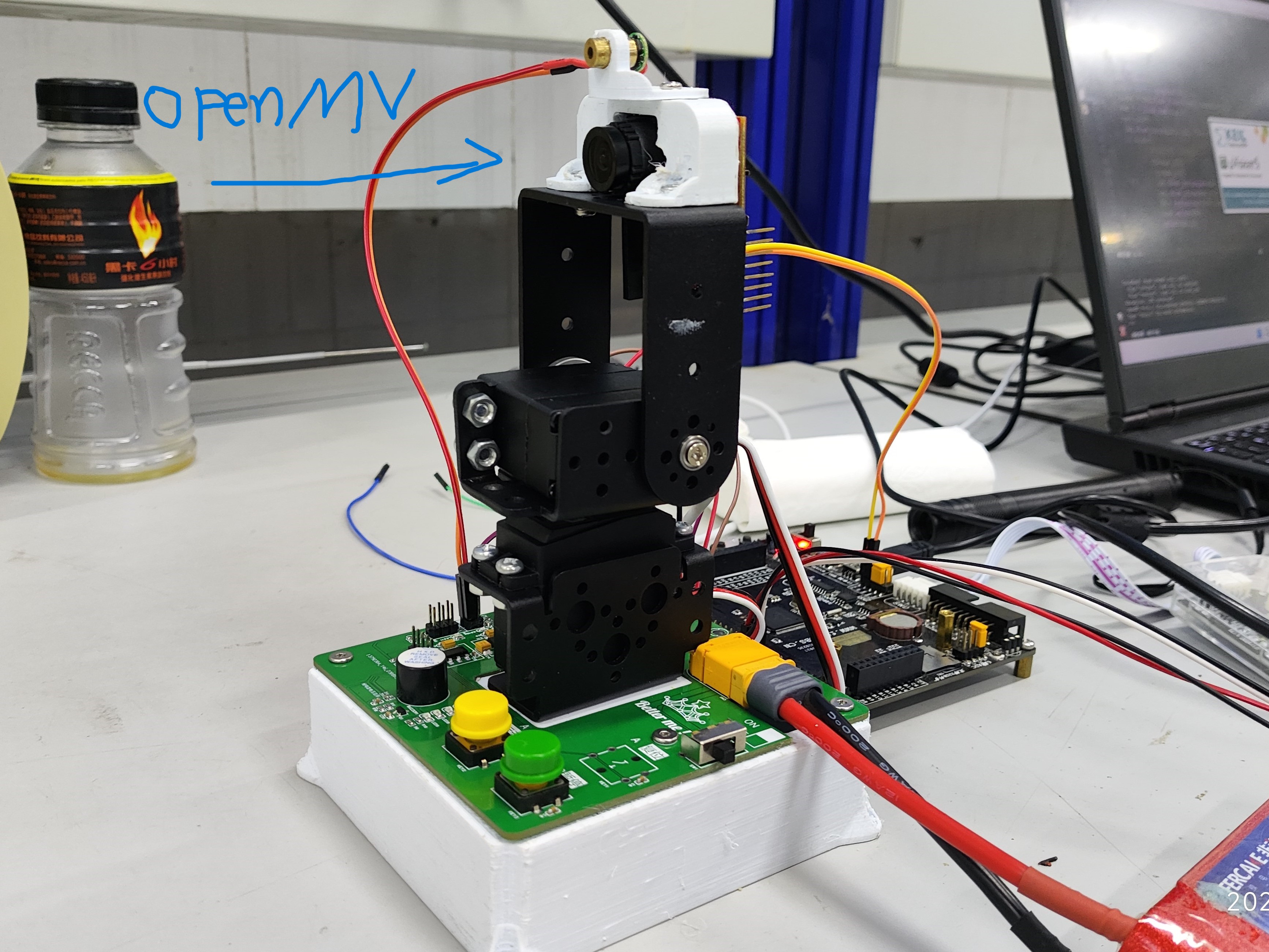
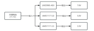
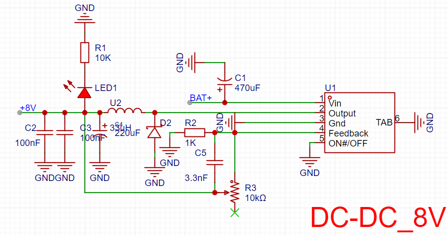
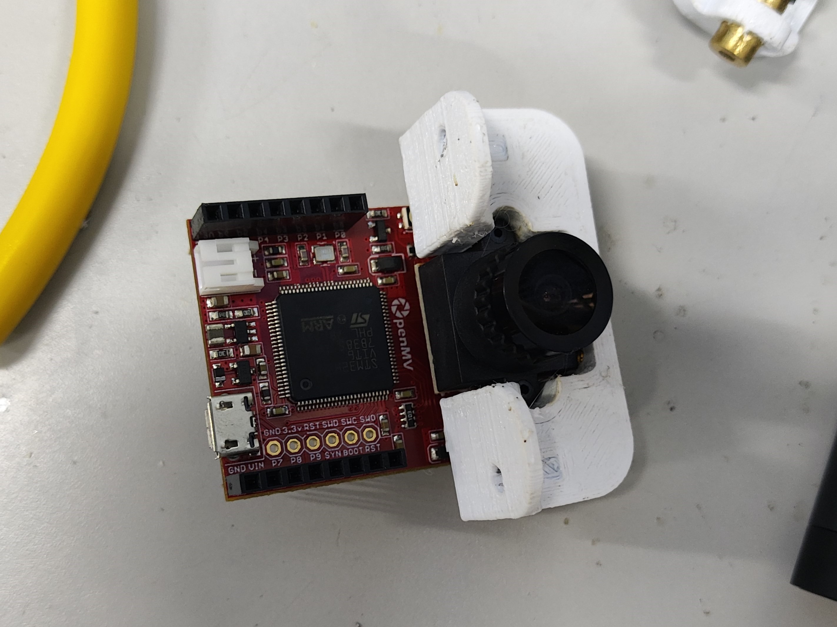
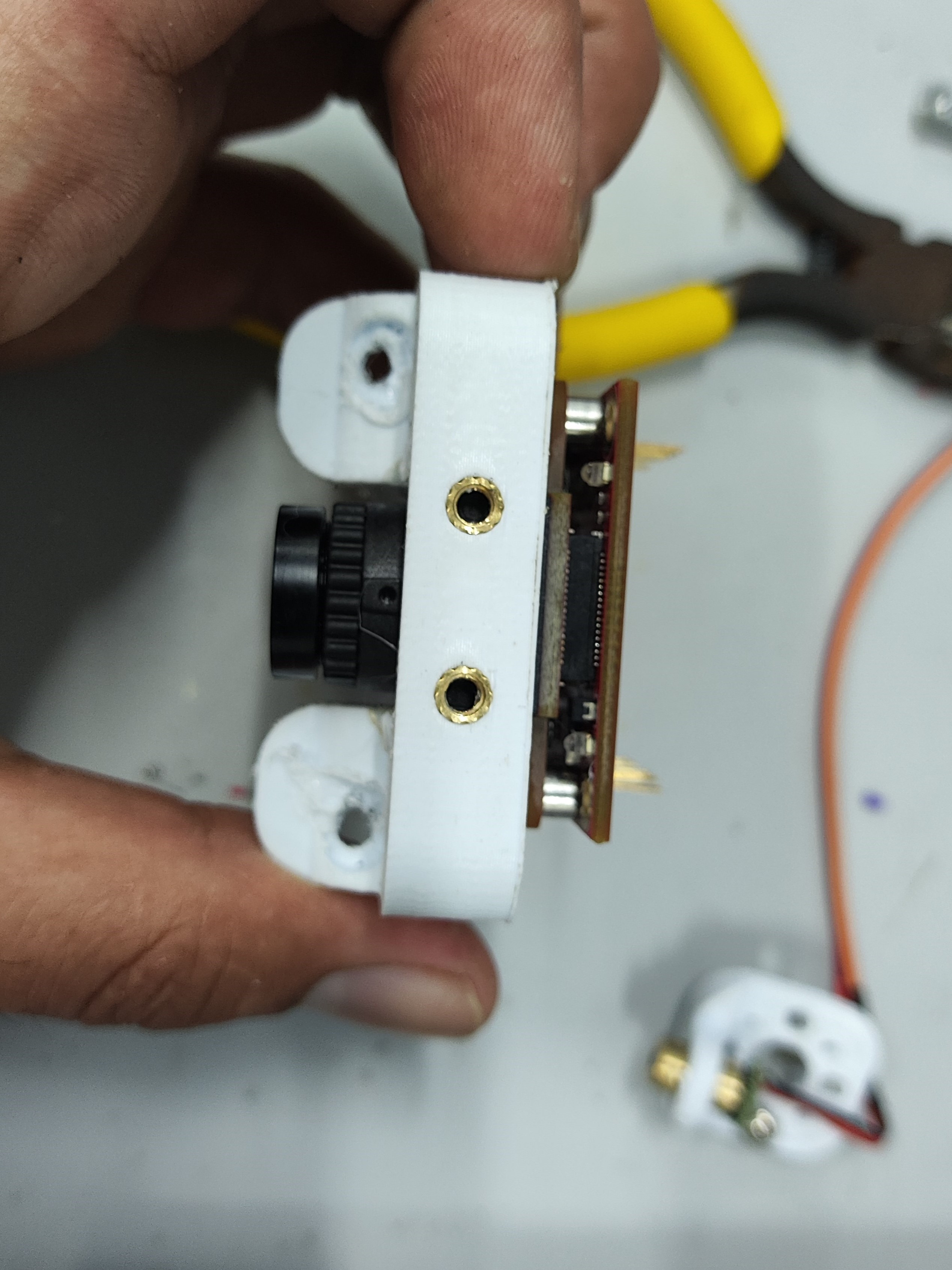
It integrates 3 power supplies: 1 DC-DC (LM2596S) servo power supply, 1 5V LDO (AMS117) OpenMV power supply, and 1 3V3 (AMS117) power supply for other modules; it also integrates sound and light alarms, buttons, and RGB lighting.
Overview: This PCB
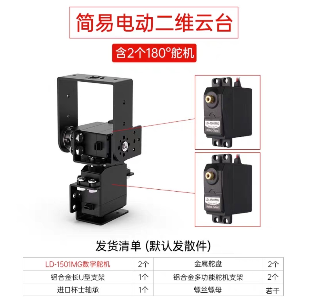
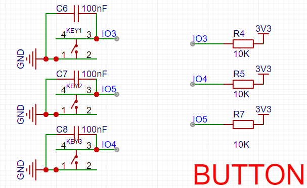
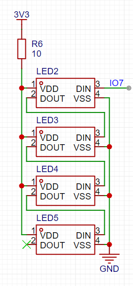
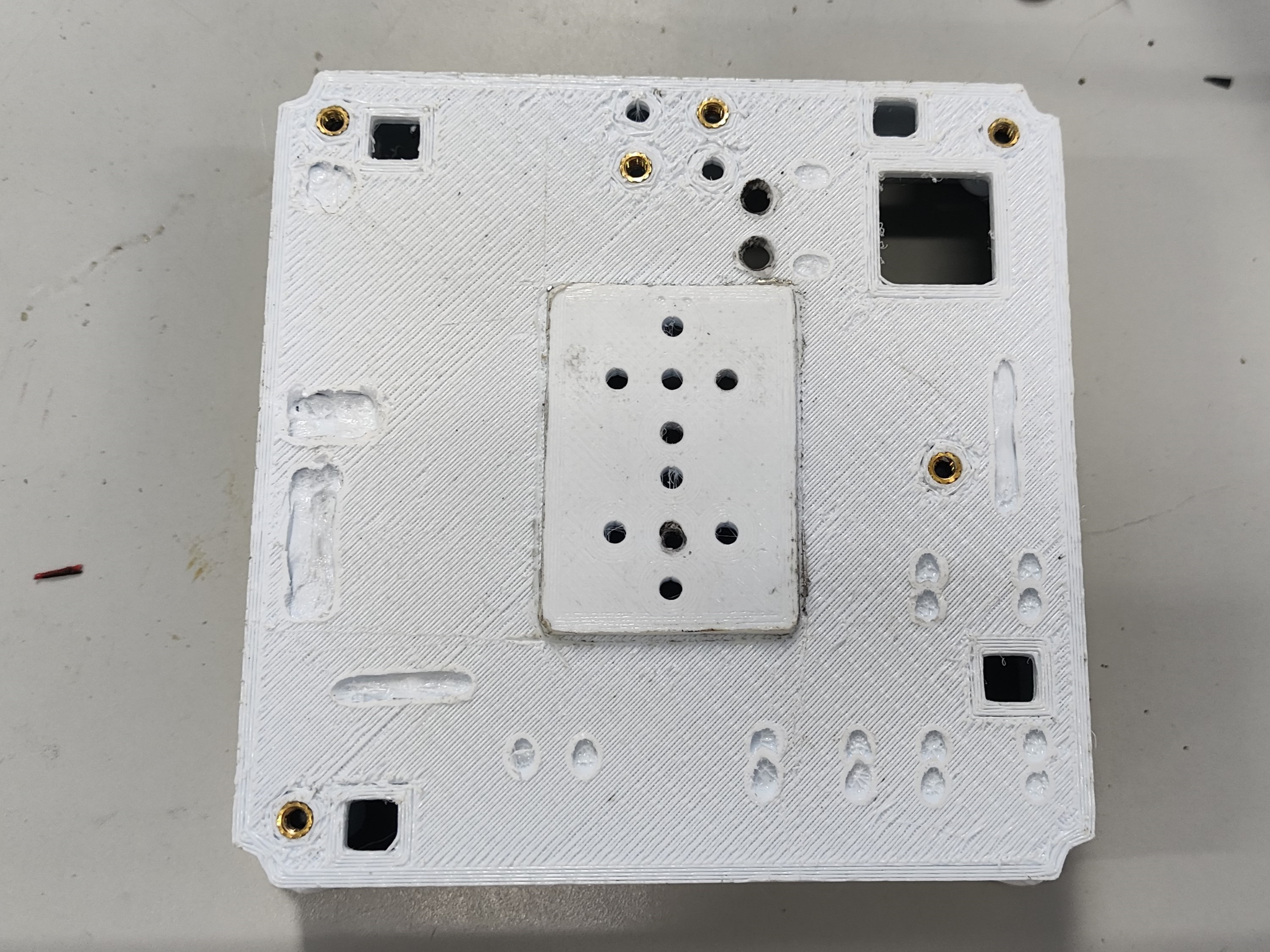
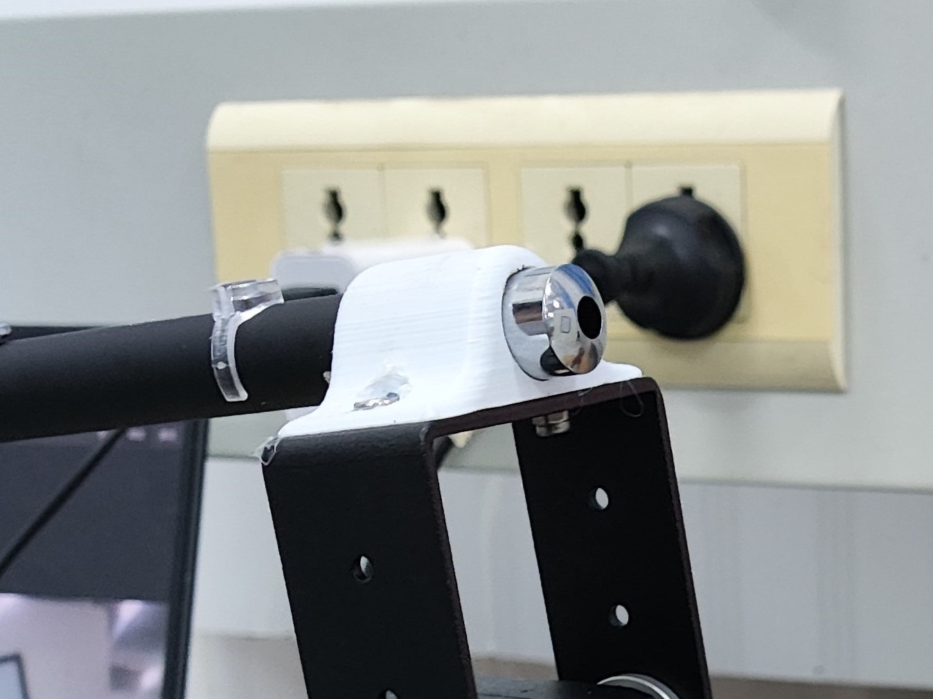
integrates three power supplies: one DC-DC (LM2596S) servo power supply, one 5V LDO (AMS117) OpenMV power supply, and one 3V3 (AMS117) power supply for other modules. It also integrates audible and visual alarms, buttons, and RGB lighting. Suitable for a simple electric 2D gimbal, as shown in Figure B (PCBA), which only requires two buttons. Circuit Module Design: Power supply is a 3S model aircraft battery. DC-DC : The DC-DC chip is LM2596S-ADJ, with a maximum output current of 3A and adjustable voltage, meeting the requirements for simple electric 2D gimbal operation. LDO: The LDO chip is AMS1117, with a maximum output of 1A, easily meeting the power requirements of the OpenMV circuit. The circuit is simple and easy to solder. R15 and R16 are 0Ω connected to a common ground, protecting the OpenMV from servo operation. Other Functional Module Design: Button Module: C6, C7, and C8 are for hardware debounce. Buttons are pulled up by default, and the level is low when pressed. The buzzer in the audible and visual alarm module is an active buzzer. In the design, the buzzer is connected in parallel with the LED, so only one IO needs to be controlled to achieve the audible and visual alarm function. R8 and R9 are shorting positions for 3V3 and 5V power supply, respectively; short one according to your needs. The RGB module design is purely for fun. If you want to use this, please choose a transparent material for the base printout, and place the RGB on the bottom layer of the PCB. The screw holes on the A and B device bases are injection-molded hot-melt copper nuts embedded after printing (some holes are designed relatively small, and the nuts contain printing material; the hole diameter should be enlarged before use). The final effect is excellent and looks very nice. Also, since some PCBAs are through-hole components, some space needs to be left on the printout (this was not considered or not planned during the design). Holes were drilled in the PCBA, and then a soldering iron was applied. For device A—the laser pointer— the laser pointer diameter is 14mm, which is perfect for fixing and also allows for easy removal. However, the distance between the two holes for mounting to the pan-tilt head is a bit too close; it should be increased by 2-3mm. The design was based on the simple electric 2D pan-tilt head 3D file provided by the vendor (blame me again). Device B - the OpenMV mounting bracket directly mounts the OpenMV camera; be careful when using it! If it doesn't fit, use a soldering iron to gently warm it up, but don't use force! However, the distance between the two holes for mounting to the pan-tilt head is a bit too close; it should be increased by 2-3mm. The design was based on the simple electric 2D pan-tilt head 3D file provided by the vendor (blame me again). An embedded injection-molded nut facilitates the next step of laser light installation. Device B - the laser light mounting bracket was initially designed to be mounted directly on the pan-tilt head, but later the space was given to the OpenMV, so it's now mounted above the OpenMV. Summary : 1. Prepare equipment in advance or immediately. We only received the OpenMV at noon on August 4th, resulting in insufficient development and debugging time, which was a huge loss. 2. We didn't conduct extensive testing before packaging. Before packaging, we needed to test in different locations and under different light intensities; we only tested it once, which was a huge loss! 3. Health is very important! During the days of the competition , I stayed up all night, mainly because I had nothing to work on and couldn't make any progress. The PCB design was completed on the first night of the competition. That night, around 3 or 4 AM, a small dog knocked on the door, then went out and barked in the hallway—something's up. There was also a large bug, about 5 centimeters long, covered in legs—creepy, but I didn't take a picture. The video shows the RGB testing, the appearance of device A and device B, and the little dog.


VID_20230805_153150.mp4
QQ Video 20230810114635.mp4
Electronic Design Contest_3D Printing Files.zip
2EB09818D5E672E74F4703B690C0160E.mp4
VID_20230806_032446.mp4
PDF_【2023 Electronic Engineering Contest】Problem E - Experimental Platform.zip
Altium_【2023 Electronic Engineering Contest】Problem E - Experimental Platform.zip
PADS_【2023 Electronic Engineering Contest】Problem E - Experimental Platform.zip
BOM_【2023 Electronic Engineering Contest】Problem E - Experimental Platform.xlsx
96803
PixelWeatherPCB
The ink bottle weather station I made a few years ago uses HanShuo Electronics price tags as the shell and ESP8266 as the main control chip. It is still working normally. Since development and maintenance have stopped (only urgent software bugs are fixed), it has been open-sourced to the JLCPCB platform.
The weather station source code has had all signatures and encryption verifications removed. After creating the PCB, the firmware can be directly flashed. It is not restricted to any use by anyone for any purpose; secondary development is not the responsibility of the author.
eagle.flash.bin
0x0
(required),
eagle.irom0text.bin
0x10000
(required),
esp_init_data_default_v05.bin
0x3fc000
(required only for the first flash
). Special thanks to users who previously purchased the software!
More information can be found at: https://www.cnblogs.com/yanye0xcc/p/14994806.html
Hosted on GitHub (emergency bug fixes will be provided here):
https://github.com/Yanye0xFF/PixelWeather
eagle.flash.bin
eagle.irom0text.bin
esp_init_data_default_v05.bin
PDF_PixelWeatherPCB.zip
Altium_PixelWeatherPCB.zip
PADS_PixelWeatherPCB.zip
BOM_PixelWeatherPCB.xlsx
96805
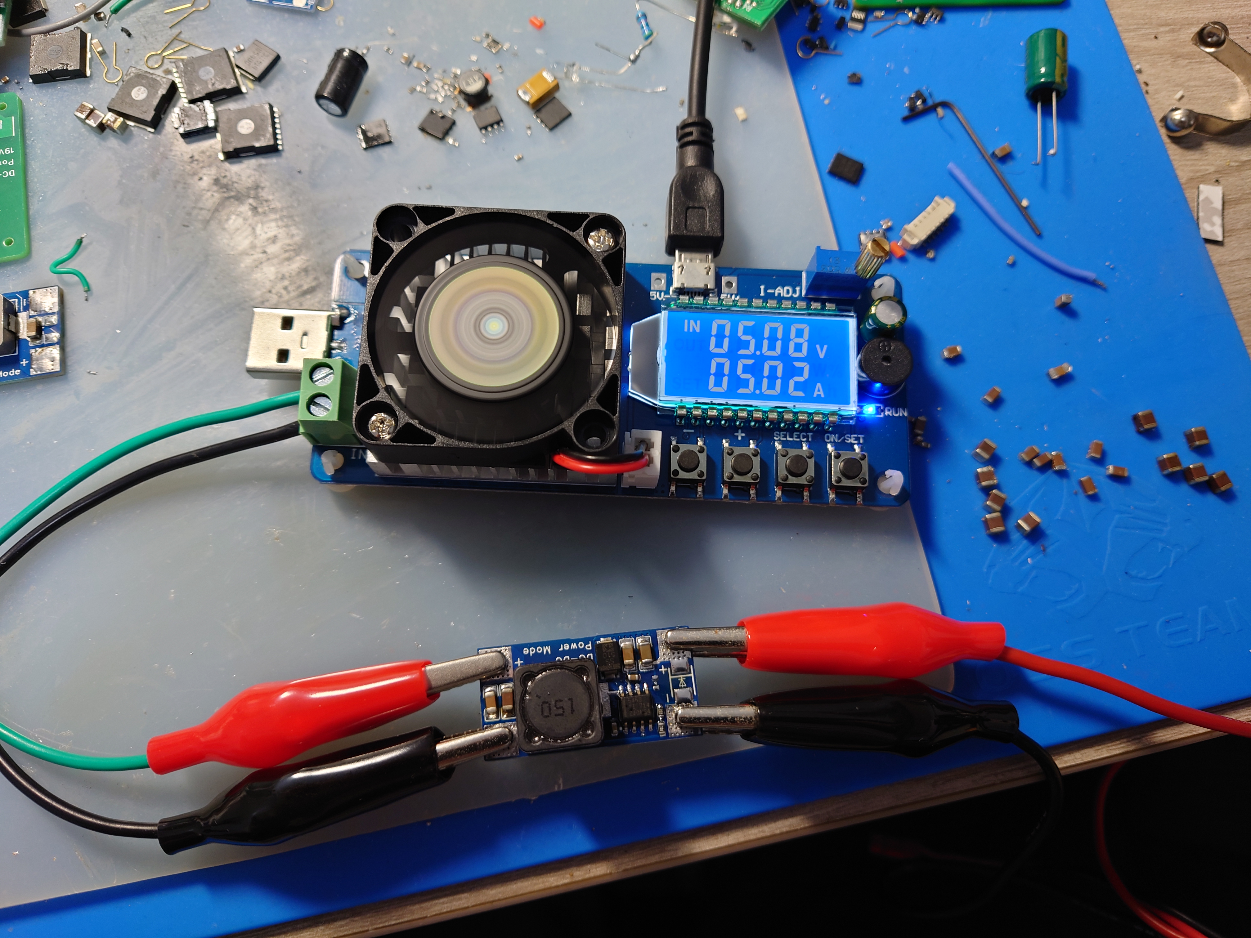
TPS5450 step-down module verification board
The TPS5450 is a high-output-current PWM converter that integrates a low-resistance high-side N-channel MOSFET. It includes a high-performance voltage error amplifier, undervoltage lockout circuitry, an internally integrated slow-start circuit, and a voltage feedforward circuit.
Wide input voltage range: 5.5V to 36V;
Up to 5A continuous (6A peak) output current;
Greater than 90% efficiency achieved through a 110mΩ integrated MOSFET switch;
Wide output voltage range: Adjustable down to 1.22V with 1.5% initial accuracy;
Internal compensation minimizes the number of external components;
Suitable for small filter sizes; Fixed 500kHz switching frequency;
18µA shutdown current;
Improved line conditioning and transient response through input voltage feedforward;
System protected against overcurrent, overvoltage, and thermal shutdown;
–40°C to 125°C operating junction temperature range
; Utilizes a small, thermally enhanced 8-pin SOIC PowerPAD™ package;
Input 24V, Output 5.3V 5A tested and working; Enhanced cooling is required for long-term full-load operation.
tps5450.pdf
PDF_TPS5450 step-down module verification board.zip
Altium_TPS5450 step-down module verification board.zip
PADS_TPS5450 step-down module verification board.zip
BOM_TPS5450 step-down module verification board.xlsx
96806
ROS Ackerman Simplification
This is a simplified control board for the lower-level machine of an Ackerman ROS robot. It's a beginner's drawing board and not very mature.
Includes an STM32C8T6 minimum system board, motor drive module, MPU6050/6500, MINI560 step-down module, DRV8833 motor driver, and a reserved Bluetooth interface. It can implement basic functions as a lower-level controller for ROS vehicles. Because it only provides two motor interfaces, one motor module, and one PWM interface for controlling the servo motor, it can be used as a control board for Ackerman vehicles. It can also be modified to control two-wheel differential vehicles and other types of vehicles as needed.
PDF_ROS Ackerman Simplified.zip
Altium_ROS Ackerman Simplified.zip
PADS_ROS Ackerman Simplified.zip
BOM_ROS Ackerman Simplified.xlsx
96807
LM5122 Boost Module 12V to 24V 5A Dual Phase - [Refer to Official Layout]
LM5122 12V to 24V dual-phase module
This is a 12V to 24V module based on the LM5122QMHX boost converter chip, with layout and parameters automatically generated by TI tools.
Theoretically, it can output 10A of high current with a 240W load, but the actual output depends on the components used; without a load tester, the exact figures are unclear.
The inductor used is a domestic PQ2615, 10uH 30A.
An extended dual-phase interface is provided, with wiring instructions printed on the board. For extended use, the input and output need to be connected in parallel.
The extended dual-phase interface works normally in actual testing; however, its effectiveness is unknown. Further verification with an oscilloscope is needed; proceed with caution when prototyping.

PDF_LM5122 Boost Module 12V to 24V 5A Dual Phase_【Refer to Official Layout】.zip
Altium LM5122 boost module 12V to 24V 5A dual-phase [Refer to official layout].zip
PADS_LM5122 Boost Module 12V to 24V 5A Dual Phase_【Refer to Official Layout】.zip
BOM_LM5122 Boost Module 12V to 24V 5A Dual Phase_【Refer to Official Layout】.xlsx
96809
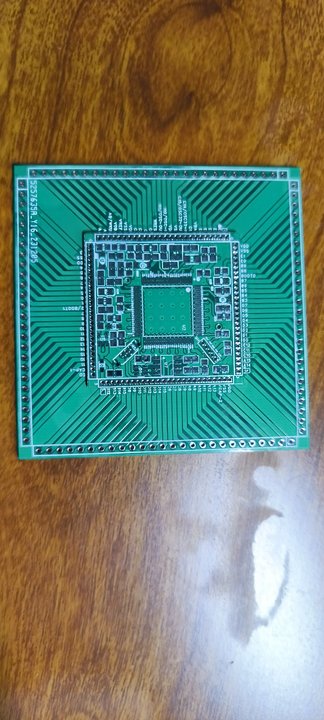
STM32F407VET6 Minimum Development Board 2.0
The STM32F407VET6 minimum system development board 2.0 has been successfully prototyped and tested, but has not yet been soldered. Optimization is currently at this stage. Discussion and guidance are welcome. (Only group: 289917684)
The STM32F407VET6 minimum system development board 2.0 has been successfully prototyped and tested, but has not yet been soldered. In previous versions, the 1.27mm header pins were found to be too expensive, so a baseboard was added to solder the core board onto it. The solder pads on the baseboard will be lengthened later for easier soldering. This is the current optimization. Discussion and guidance are welcome. (Only group: 289917684)
PDF_STM32F407VET6 Minimum Development Board 2.0.zip
Altium_STM32F407VET6 Minimum Development Board 2.0.zip
PADS_STM32F407VET6 Minimum Development Board 2.0.zip
BOM_STM32F407VET6 Minimum Development Board 2.0.xlsx
96810
electronic


 京公网安备 11010802033920号

 M1302
M1302


