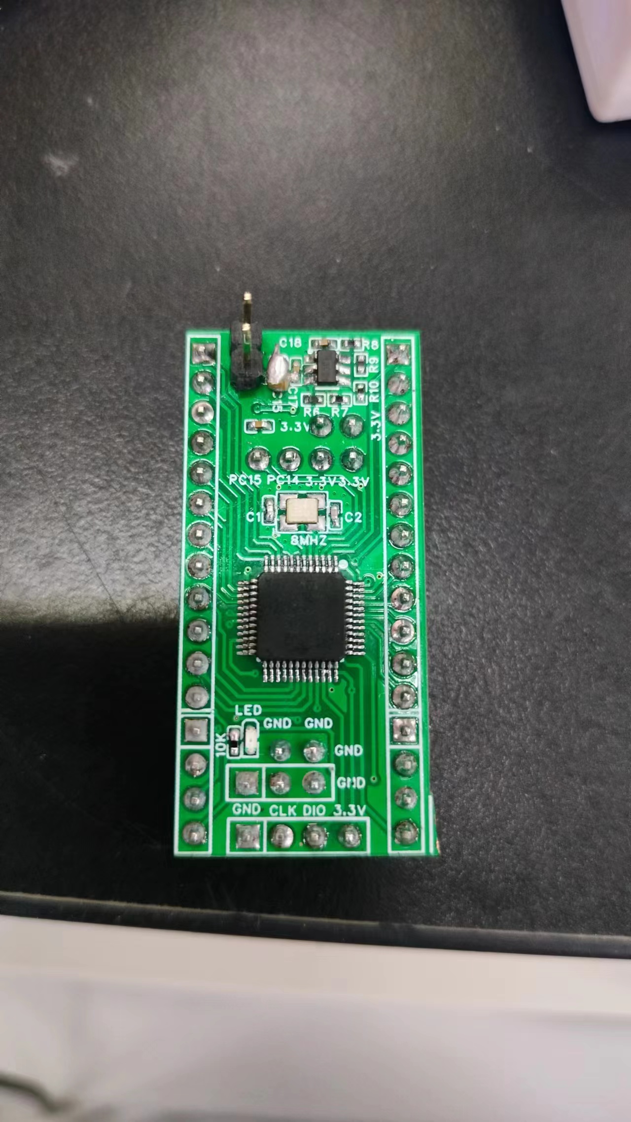
PS: I've also reserved soldering pins for the DHT11 temperature and humidity sensor on the development board for easy data acquisition and verification later.
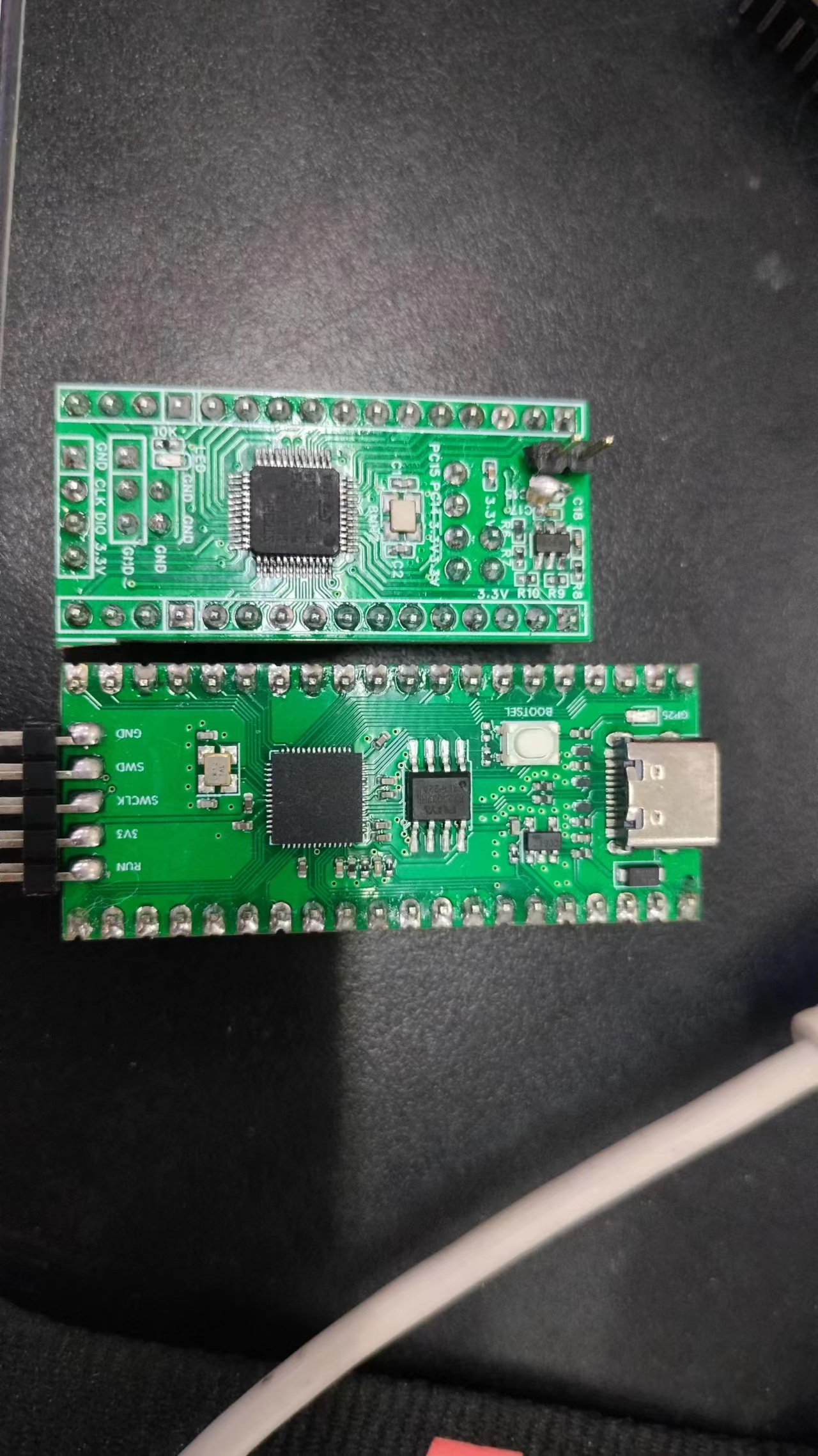
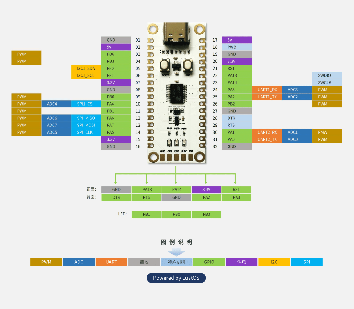
The Hezhou Air001 is a TSSOP20 packaged MCU, employing a high-performance 32-bit ARM® Cortex®-M0+ core, with 32Kbytes of Flash and 4Kbytes of RAM. The chip integrates multiple USART, IIC, SPI, and other communication peripherals, five 16-bit timers, one 12-bit ADC, and two comparators. For detailed information, please refer to the datasheet: AIR001 Chip Datasheet.pdf and the Air001 Register Manual.
port downloading, connect the serial module's RX pin to the Air001's TXD (PA2), connect the serial module's TX pin to the Air001's RXD (PA3), and connect the chip's or development board's GND to the serial module's GND.
. After the download is complete, you may need to manually press the RST button to reset and
resume normal operation. Note
: This development board does not have an automatic download circuit; you need to manually enter the bootloader to download.
, the wiring is as follows: connect the debugger's SWDIO to Air001's SWDIO (PA13), connect the debugger's SWCLK to Air001's SWCLK (PA14), and connect the chip's or development board's GND to the debugger's GND.
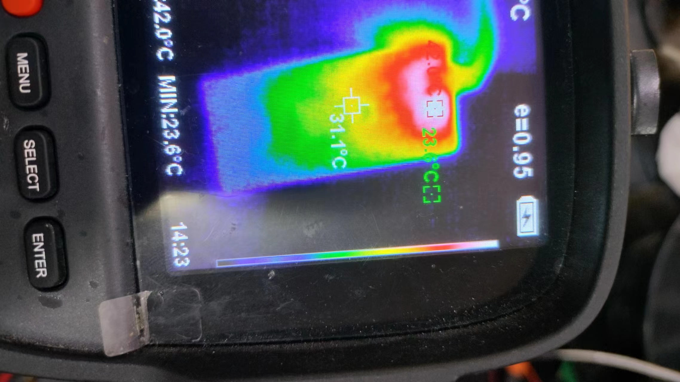
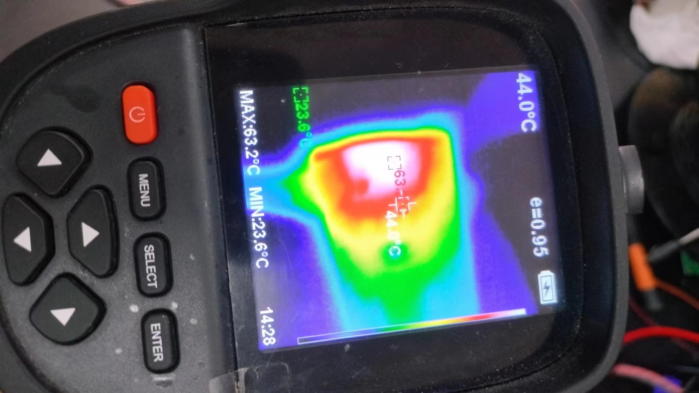
This paper designs and implements an ambient temperature detector based on the STC32 microcontroller, which can accurately detect the ambient temperature, display the temperature value, draw a line graph, and record the time.
The overall system design of this project uses an STC32 microcontroller as the core controller. A DS18B20 temperature sensor detects the ambient temperature, transmits the data to the microcontroller for processing, and then displays the temperature value on a 2.8-inch TFT LCD screen, plotting a line graph of the temperature change over time. A DS1302 microcontroller records the time. For power supply, a Type-C charging interface provides direct power. Considering power outages, a lithium battery is used as a backup power source, charged by a TP4056 charging chip. A P-channel MOSFET is used for power switching, and an RT9193 converts the power to 3.3V to power subsequent circuits. A passive buzzer is also included to alert the user.
1. The main controller uses an STC32 microcontroller as the core controller. Domestic chips are relatively inexpensive, suitable for low-cost applications. They also have a relatively complete Chinese manual, with detailed explanations of virtual serial port and SPI communication used in this project, making development easy and suitable for beginners.
2. The DS18B20 temperature sensor is used for temperature acquisition. The DS18B20 is a single-bus digital temperature sensor with advantages such as small size, low power consumption, and high accuracy. Its working principle is to detect temperature changes by measuring the resistance change of a thermistor, and then convert the temperature value into a digital signal output. In this project, we connect the DS18B20 to the I/O port of an STC32 microcontroller, which reads and processes the temperature value.

3. Temperature display uses a 2.8-inch TFT LCD screen to display the temperature value and line graph. TFT LCD screens have advantages such as vibrant colors, clear images, and wide viewing angles. Their working principle is to control the rotation angle of liquid crystal molecules through thin-film transistors to achieve image display. In this project, we connect the TFT LCD screen to the SPI interface of the STC32 microcontroller. The microcontroller reads the DS18B20 temperature data, processes and displays it according to the current time, and confirms the coordinates by sequentially marking points on the screen to obtain the line graph.


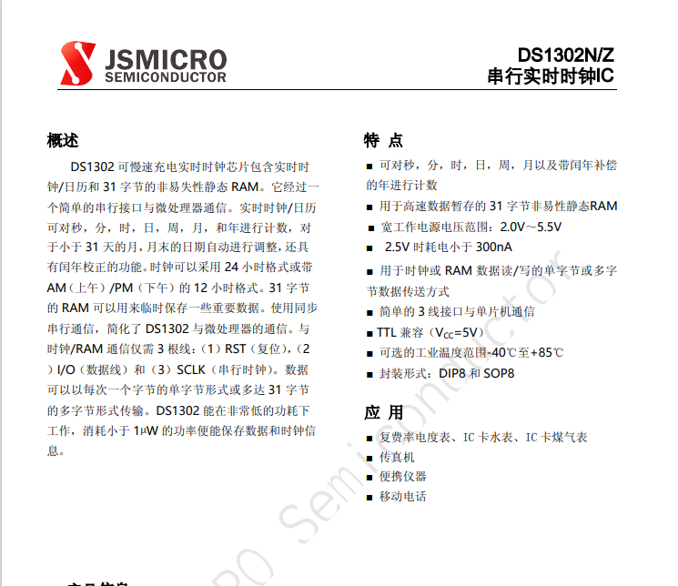
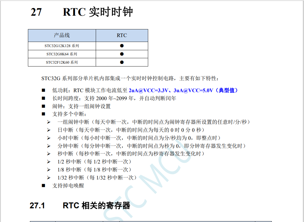
4. Time is achieved using a DS1302 clock chip. The DS1302 is a trickle-charged clock chip from Dallas Semiconductor. It contains a real-time clock/calendar and 31 bytes of static RAM, and can communicate with a microcontroller via a simple serial interface. It features a simple 3-wire interface, and the real-time clock calculates seconds, minutes, hours, date, month, day, week, year, and leap year compensation valid until 2100. It supports battery-powered general-purpose RAM, operating from 2.0V to 5.5V, using less than 300nA of current at 2.0V. The end-of-month date is automatically adjusted for months with fewer than 31 days, including leap year corrections. The clock runs in 24-hour or 12-hour format, and the AM/PM indicator uses synchronous serial communication, simplifying the interface between the DS1302 and the microprocessor. Alternatively, the internal RTC real-time clock of the STC32 can be used, requiring an external 32.768kHz crystal oscillator.
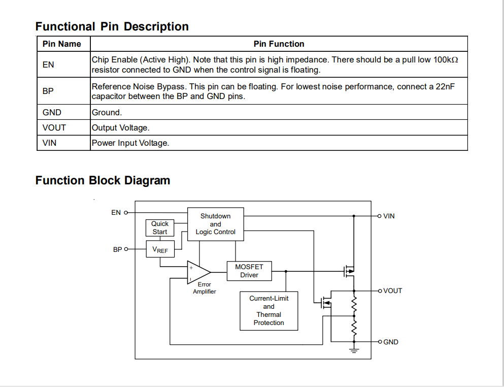
While a Type-C power supply is used directly, a lithium battery is added as a backup power source to prevent power outages that would disable the entire system and lose time data on the DS1302. A TP4056 charging chip is used for charging, and a P-channel MOSFET is used for power switching. The output voltage is converted to 3.3V by an RT9193 power conversion chip to power the subsequent circuitry.
The RT9193 is an LDO linear regulator with a 300mA output current, ultra-low noise, and fast adjustment. At full power (300mA) output, the voltage drop can be as low as 220mV. Its input voltage range is 2.2V to 5.5V, and its output voltage is 3.3V. It features overcurrent and short-circuit protection. The RT9193 uses an SOT23-5 package.
Circuit Design Summary: In this project, we used advanced components such as a temperature sensor, LCD display, clock chip, and power management chip. Through reasonable circuit design and software programming, we achieved the functionality and coordinated operation of each component. Specifically, we used a DS18B20 temperature sensor to detect the ambient temperature, a 2.8-inch TFT LCD screen to display the temperature values and line graphs, a DS1302 clock chip to record time, and a lithium battery for power supply and a TP4056 charging chip for charging management. Through the coordinated operation of these components, we successfully implemented the functions of detecting, displaying, and recording ambient temperature.
Component Preparation: Before circuit installation, the necessary components must be prepared. The components required for this project include an STC32 microcontroller, a DS18B20 temperature sensor, a 2.8-inch TFT LCD screen, a DS1302 clock chip, a TP4056 charging chip, a P-channel MOSFET, an RT9193 power conversion chip, a lithium battery, and a passive buzzer. When purchasing components, attention should be paid to their model, specifications, and quality to ensure the normal operation of the circuit. All components for this project can be purchased from LCSC Online Store.
Soldering and Connection: After preparing the components, the soldering and connection of the components began. First, the components need to be inserted onto the circuit board according to the circuit diagram, and then soldered using a soldering iron. When soldering, pay attention to the following points:
1. Soldering time should not be too long, generally no more than 3 seconds, to avoid damaging the components or the circuit board.
2. The soldering temperature should be moderate, generally around 350℃. Too high a temperature will damage the components or deform the circuit board, while too low a temperature will result in poor soldering.
3. A "three-step method" can be used for soldering. First, heat the soldering iron to the appropriate temperature, then place the solder wire on the solder joint, and finally use the soldering iron to melt the solder wire and wet the solder joint. Maintain the stability and uniformity of the soldering iron during soldering to avoid problems such as cold solder joints or poor soldering.
4. Pay attention to safety during soldering to avoid dangers such as electric shock or burns. Also, keep the soldering environment clean and tidy to avoid dust or debris affecting the soldering quality.
Debugging Preparation: After the circuit is installed, circuit debugging is required to ensure the circuit works properly. Before debugging the circuit, the following preparations need to be made:
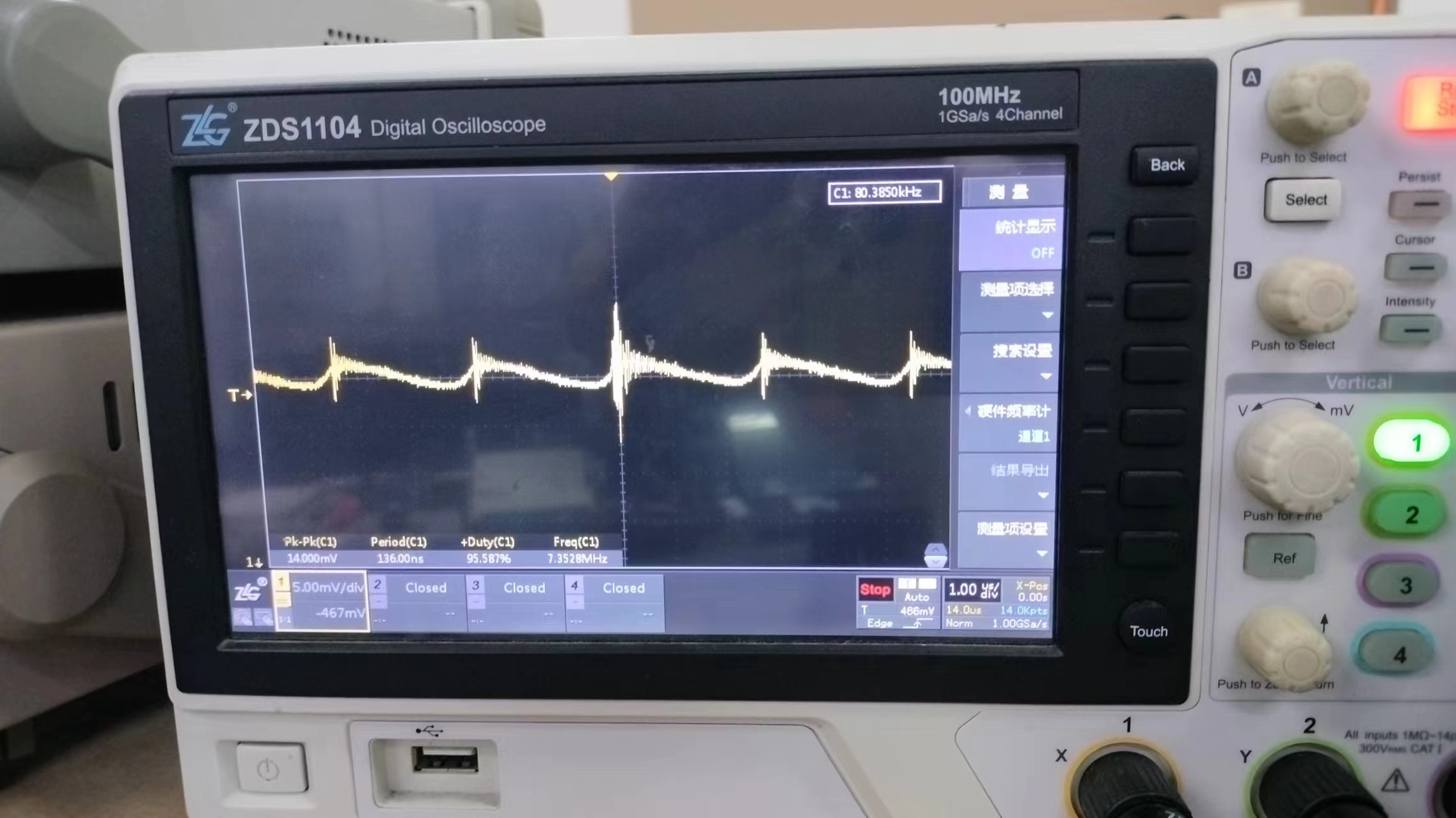
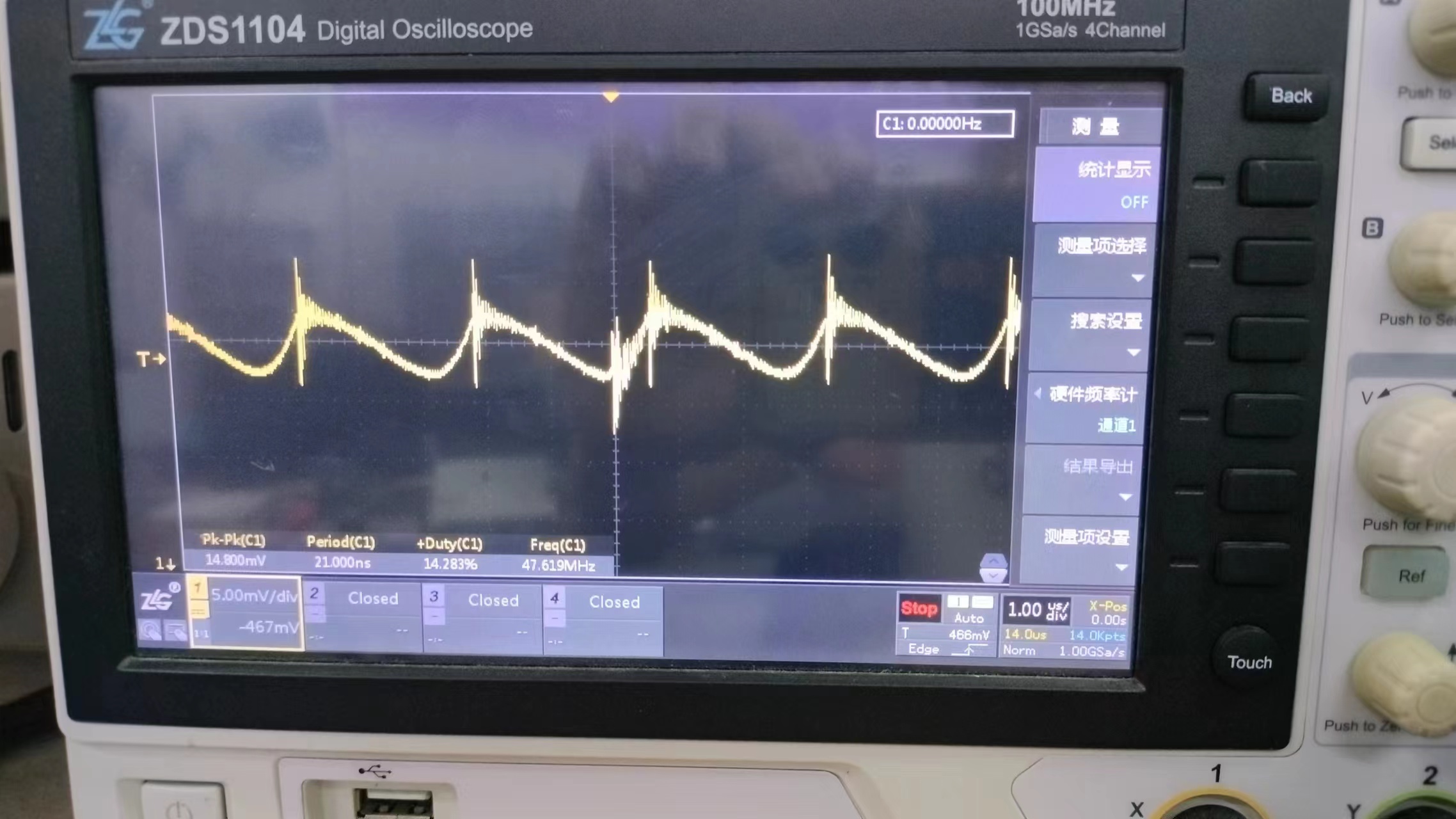
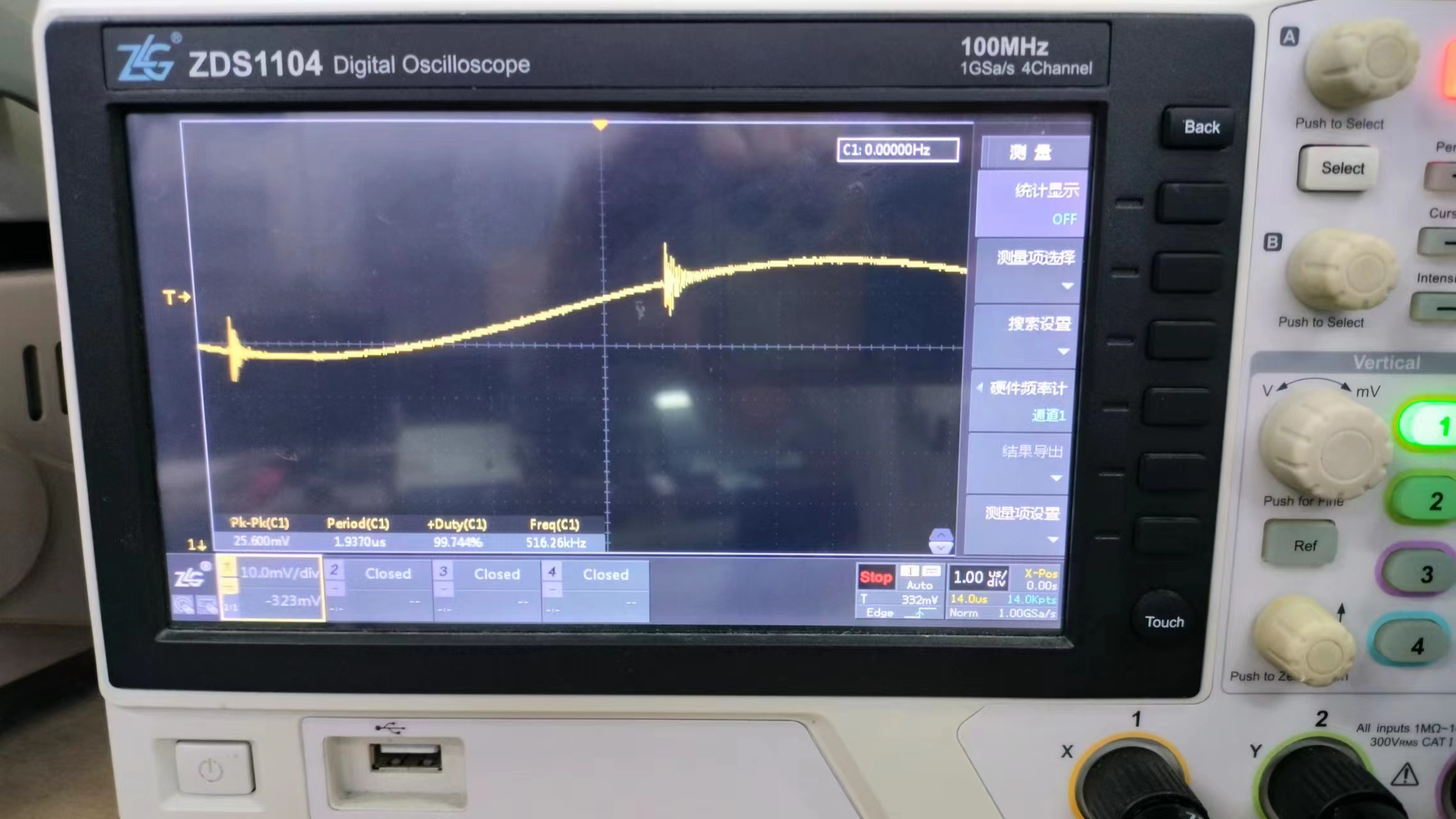
Check whether the connections between the components on the circuit board are correct and reliable, and whether there are any problems such as cold solder joints or short circuits. Check whether the power supply is normal, and whether there are any problems such as excessively high or low voltage. Prepare the necessary testing tools, such as multimeters and oscilloscopes, for measurement and observation during debugging. Write test programs according to the functional requirements of the circuit to verify functionality and perform performance testing during debugging.
Debugging techniques: Start debugging with simple functions and gradually transition to complex functions. This allows for step-by-step troubleshooting and avoids solving multiple problems at once. Divide the circuit into different modules and debug them separately. This makes it easier to find the problem and avoids troubleshooting the entire circuit. Keep records during debugging. Record the problems encountered and their solutions for future reference.
Debugging techniques: Through reasonable circuit design and software programming, we successfully implemented the functions of detecting, displaying, and recording ambient temperature. During circuit debugging, we adopted techniques such as modular debugging and the use of simulation software to improve debugging efficiency. Through debugging, we verified the various functions and performance indicators of the circuit, and also discovered and resolved some problems. Ultimately, we successfully completed the design and implementation of the ambient temperature detector.
Project Outcomes:
The implementation steps of this project included the following stages: system design, hardware construction, software programming, system testing, and system optimization. During the project implementation, we adopted advanced components and technologies, and through reasonable circuit design and software programming, we realized the functions and collaborative operation of each component. Ultimately, we successfully completed the design and implementation of the ambient temperature detector, achieving the expected goals and requirements.
The project outcomes include the following aspects:
1. Designed and implemented an ambient temperature detector capable of accurately detecting the surrounding ambient temperature, displaying the temperature value, plotting a line graph, and recording time.
2. Mastered the selection and usage methods of components such as temperature sensors, LCD displays, clock chips, and power management chips.
3. Mastered C language programming and microcontroller development technologies, realizing the functions and collaborative operation of each component.
4. This project fostered teamwork and problem-solving skills, and improved practical abilities and innovation.
Summary and Reflection: During the design and implementation of this project, we encountered some difficulties and problems, but through teamwork and cooperation, we successfully solved them. During the project's implementation, we also learned a great deal of knowledge and skills, improving our practical abilities and innovation. At the same time, we also realized some shortcomings, such as the need for further improvement and refinement in circuit design and software programming.
Through this project, we deeply understood the importance of teamwork and problem-solving skills. In future studies and work, we will continue to strive to improve our abilities and work hard to better complete projects and realize our dreams.
Final Product Showcase:
Code is attached.


 For serial
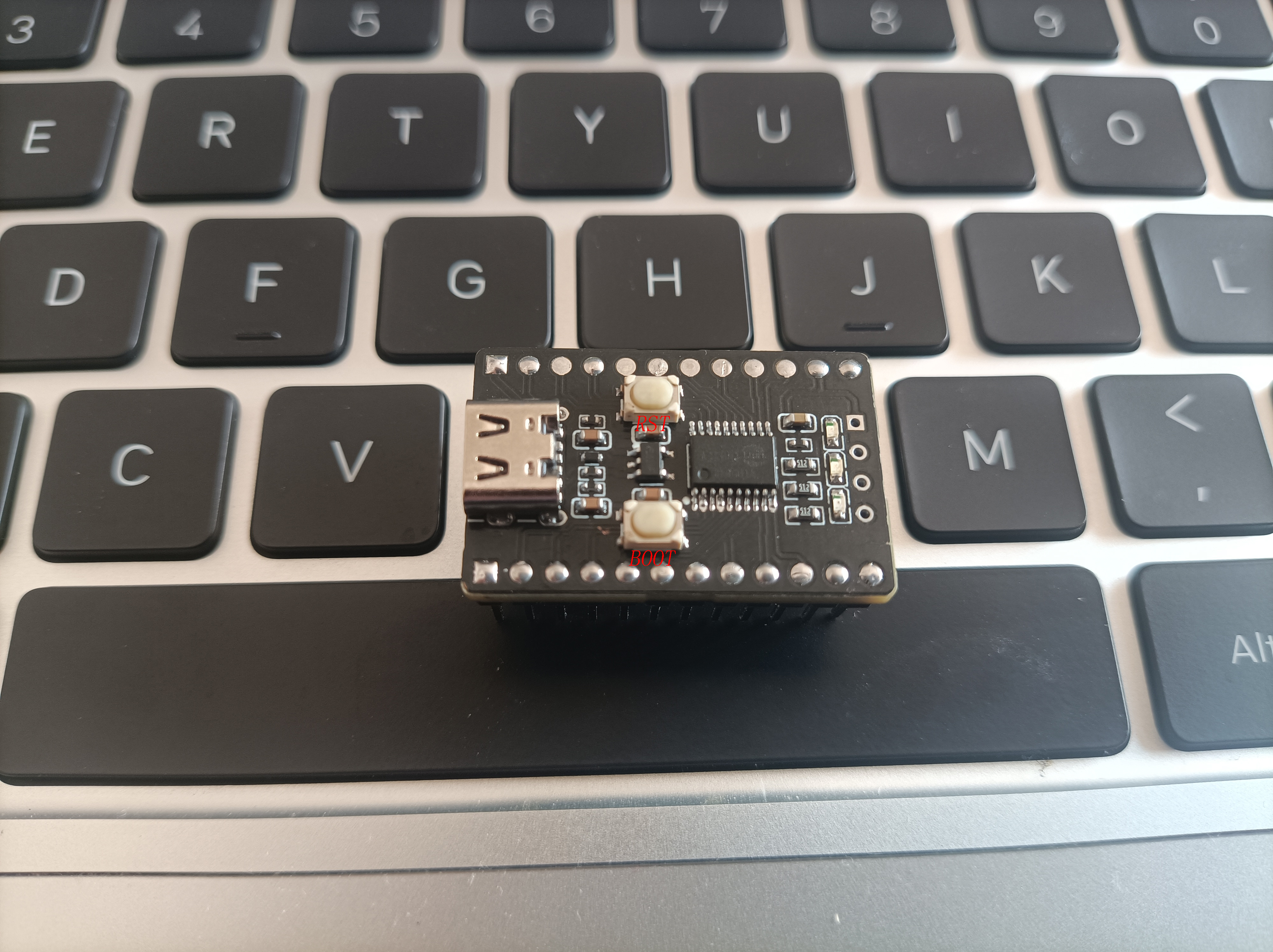


 京公网安备 11010802033920号

 PHR0402Z27R1BGW


