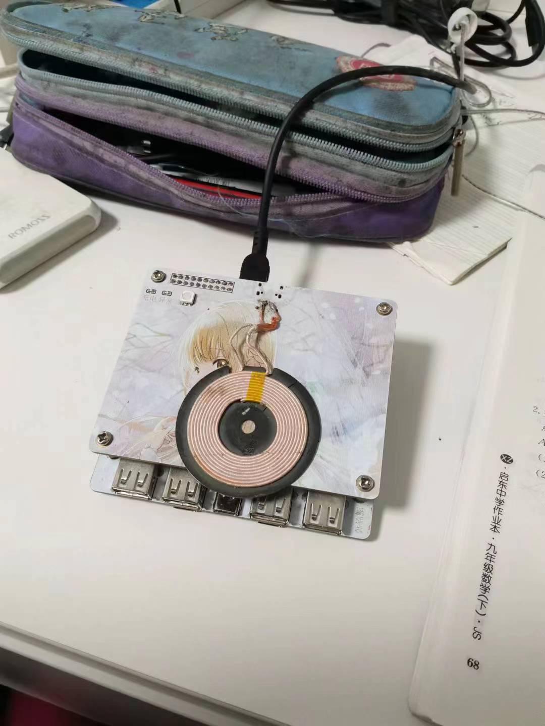
 The image below is for reference only. I have tested it on laptops, mobile phones, and PowerCC devices, and it triggers the protocol normally
 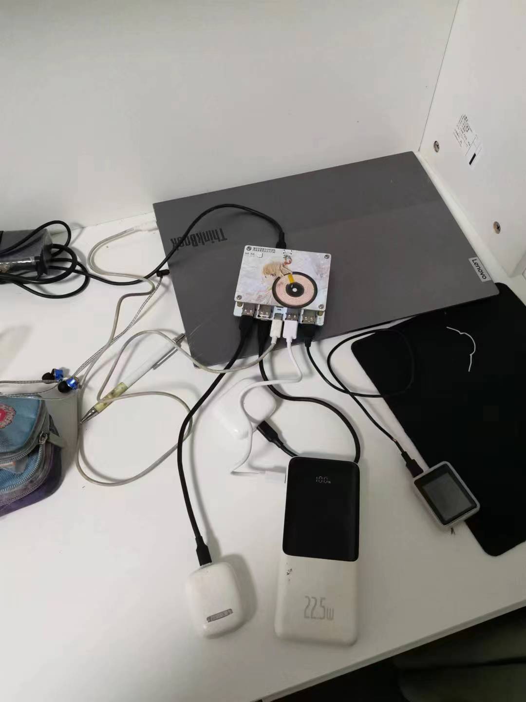 Solder only one side of the 2×10 header pins. You can also replace it with two header pins (the rest are for your own use, such as connecting another board in the middle for signal transmission when placing a microcontroller).
 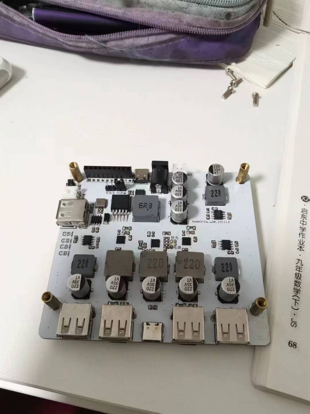 Please use 12mm long copper pillars for connection. Nylon pillars are recommended for bottom fixing; otherwise, it is not recommended to place it on a metal object (short circuit at your own risk).
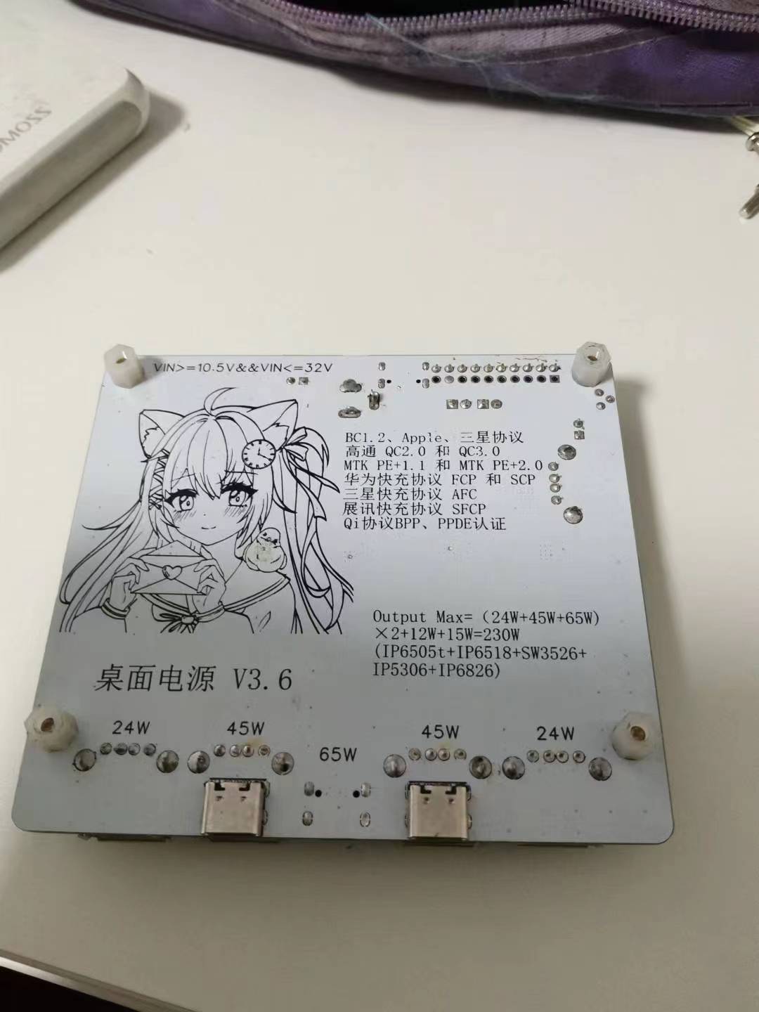

All reference designs on this site are sourced from major semiconductor manufacturers or collected online for learning and research. The copyright belongs to the semiconductor manufacturer or the original author. If you believe that the reference design of this site infringes upon your relevant rights and interests, please send us a rights notice. As a neutral platform service provider, we will take measures to delete the relevant content in accordance with relevant laws after receiving the relevant notice from the rights holder. Please send relevant notifications to email: bbs_service@eeworld.com.cn.
It is your responsibility to test the circuit yourself and determine its suitability for you. EEWorld will not be liable for direct, indirect, special, incidental, consequential or punitive damages arising from any cause or anything connected to any reference design used.
Supported by EEWorld Datasheet
EEWorld
subscription
account

EEWorld
service
account

Automotive
development
community

Robot
development
community

About Us Customer Service Contact Information Datasheet Sitemap LatestNews


Room 1530, 15th Floor, Building B,
No.18 Zhongguancun Street,
Haidian District,
Beijing, Postal Code: 100190
China
Telephone: 008610 8235 0740
 京公网安备 11010802033920号

 1103A3VREA


