The 5.83-inch monochrome e-ink screen driver board, priced at 20 yuan
, is based on the ESP32 C3. The I/O multiplexing is based on
two versions of an e-ink reader: one is a module, and the other is a bare chip,
including the RX8025T RTC, SHT40 temperature and humidity sensors, SD card and battery level detection, and a photoresistor.
Components without silkscreened parameters in the e-ink driver area need to be removed from the original driver board; they are in their corresponding positions and can be directly moved over.
Currently, it seems to work without problems; the e-ink screen drives normally. Other peripherals cannot be tested yet because there is no program, but since they are connected to the e-ink screen, they should theoretically not have any issues.
To save costs, the C3's built-in USB is used to download the program.
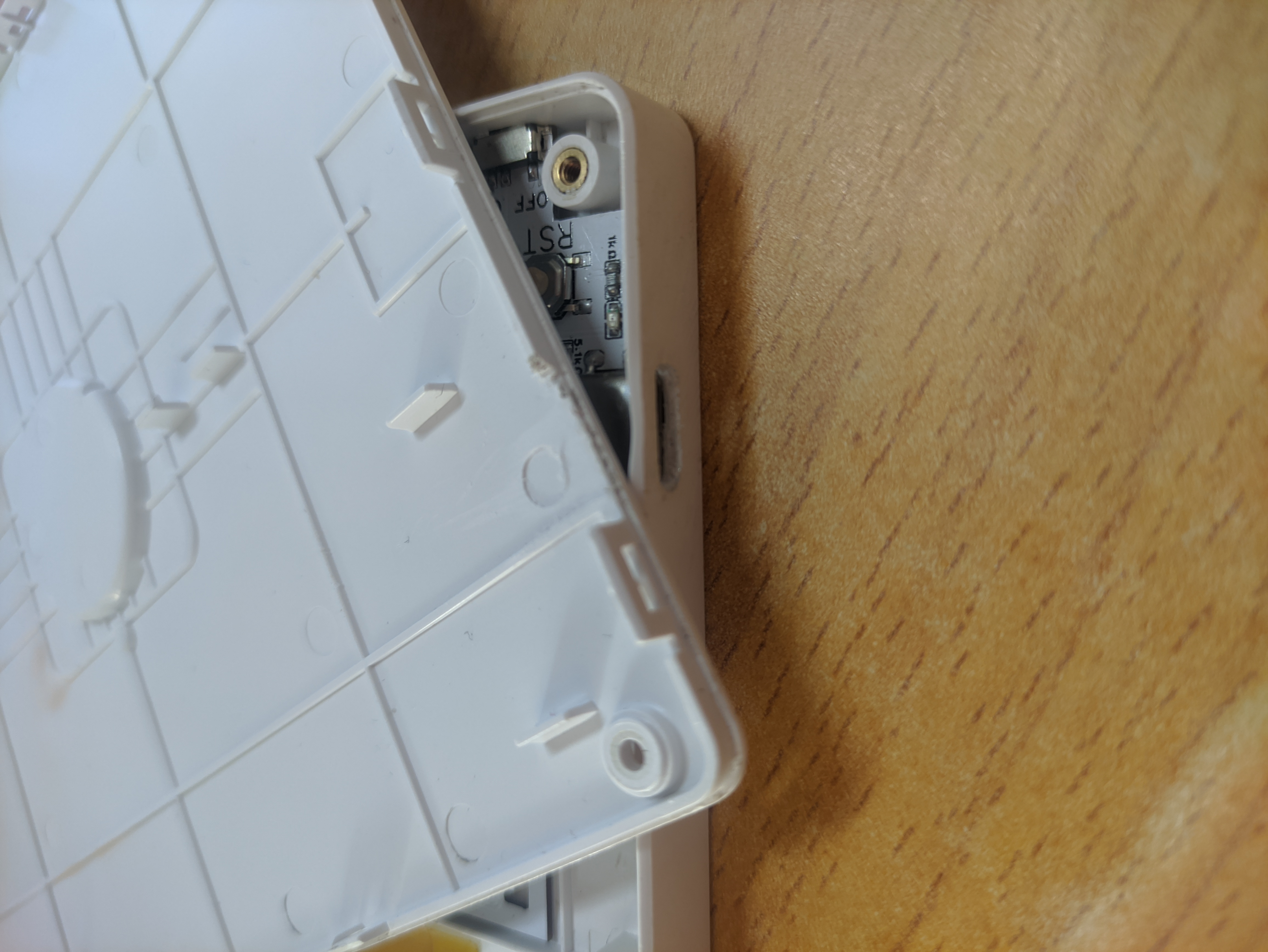
Drilling holes in the casing requires care (since you can't replace the casing if you break it). For the Type-C port, you can use a spare Type-C female connector; heat it with a soldering iron to create the hole (it's recommended to practice with spare plastic first).
The top cover of the USB-C port needs to be cut off slightly, otherwise the USB-C port will block it (see picture).
See the picture for the touch button handling.
The e-ink screen driver uses copper foil tape
. The board thickness is 0.8mm, and the RX8025 is installed by pressing it in, making sure its feet are parallel to the PCB, essentially sinking it slightly to prevent it from hitting the top.
I'm currently writing the program, so my skill level is low and it will be very slow (I'm strongly hinting to the experts to adapt it quickly). The attachment contains an Arduino local flash library. The screen doesn't natively support local flashing; it's simulated. However, aside from using a little more RAM, the local flashing effect is almost the same as a screen that natively supports local flashing.
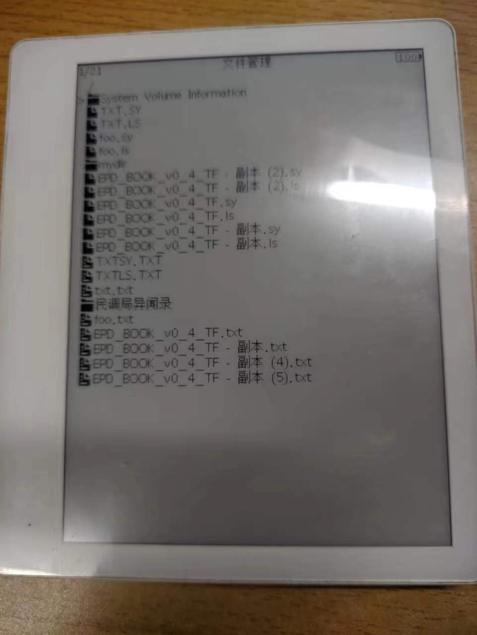
// 2023-05-07: Based on a heavily modified version of the workshop director's engineering e-ink screen TF card e-book source code, I've modified the open-source code to create a program that can read e-books. Compared to the original open-source code, it adds:
1. Battery percentage display (using a lookup table).
2. File manager.
3. Line breaks based on character width, ensuring no blank spaces at the end of even English lines.
4. Direct reading upon opening, with indexing built as you read (indexing progress is not saved; if the index is not complete before closing, it will return to the first page the next time you open it).
5. Updated index file format; no need to locate the index file, it reads directly (similar to the method used by Gancao).
6. Reading history is saved on the SD card, just like the index file (ebook filename.ls). (File), opening other files will not lose history (actually, I don't know how to use a wear leveling library like the one for licorice, and I'm afraid of writing to the internal flash, so I just put it on the card and let it level itself).
The program is in the attachment, and there may be a lot of bugs. You can send me a private message for feedback.
Tip: In version v1.1, the hardware cannot display the battery level. This has been fixed in v1.2. In version v1.1, some TF cards may not be able to display the battery level temporarily, but it doesn't matter. The program does not have a low-battery shutdown function. You can use a battery protection board for protection, or if you are skilled, you can add a 100R resistor to the PCB jumper wire of v1.2. (It is strange that on the same card, using a third-party SD library to set the SD MISO pin to output when the SD is not reading or writing can output a high level, but this library does not support Chinese file names. However, when I switch to the SD library in the ESP32 library, the TF card's MISO pin is pulled low, and the ESP32 output high level is limited by the TF card.)
//2023-10-25 Modified to a cheaper C port, and the temperature and humidity sensor was changed to SHT40.
//2023-11-22 Some users reported that excessive use of the current library caused them to be disconnected from the game. Therefore, the LUT was adjusted (a slight flickering may occur). Users who used the previous library for long-term game-wide content such as clock manipulation are advised to update as soon as possible.


5.83 e-ink screen ESP32C3 version e-reader firmware V0.3.zip
PDF_5.83-inch E-ink Screen_Driver Board.zip
Altium 5.83-inch E-ink Screen Driver Board.zip
PADS 5.83-inch E-ink Screen Driver Board.zip
BOM_5.83-inch E-ink Screen_Driver Board.xlsx
97030
A replica of a dual-channel oscilloscope based on the STM32H750VBT6.
This project originated from the JLCIC EDA Instrumentation Training Camp jointly organized by Hardwood Classroom and JLCIC. It is an oscilloscope expansion board used in conjunction with the H750 core board.
The I/O allocation in this project only applies to the Hardwood Classroom H750 core board. Please refer to the schematic diagram for specific allocation details.

The above is a 3D simulation diagram.
The physical diagram is shown below.

The software code is in the attachment of the Hardwood Classroom official website! Implementation of the
signal
conditioning circuit:
Below, we will briefly introduce the analog input and output channels on the AFE03 board. We will then introduce the design and calculation methods in detail later.
Analog input channel introduction:
This includes signal conditioning implemented with resistor voltage dividers and operational amplifiers, and a square wave output implemented with a comparator (for triggering and frequency measurement).

INA, INB: The input terminals of the oscilloscope. The pocket instrument sends an analog signal and connects to this point. Here, a 1MΩ input impedance is achieved through a series resistor voltage divider, generating two signals for selection: one is a direct input, and the other is attenuated to 1/20.
Gain: A selector switch that chooses either a direct signal or a signal attenuated to 1/20th of its input to the first-stage non-inverting amplifier. The non-inverting amplifier performs two functions: first, it amplifies the input signal at the non-inverting input by a factor of two; second, it shifts the amplified signal by 1.65V, calculated as Vo = 1.65 + 2*Vi. Therefore, the overall gain of the circuit is either 2 or 1/10.
AnalogA, AnalogB: The amplified and shifted analog signals from the non-inverting amplifier are connected to the STM32H750 development board and enter the H750's ADC.
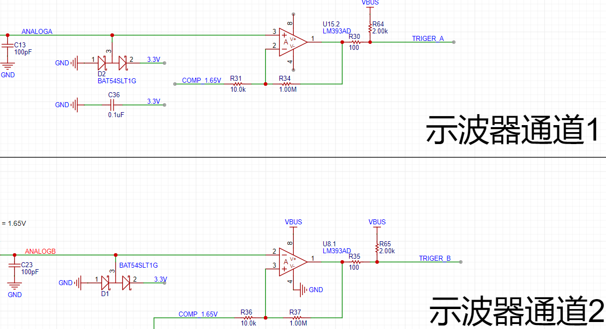
TrigerA, TrigerB: The square wave signals generated by AnalogA, AnalogB, and the DC reference level (generated by one of the H750's DACs) after passing through a comparator, enter the STM32H750's timer for frequency measurement.
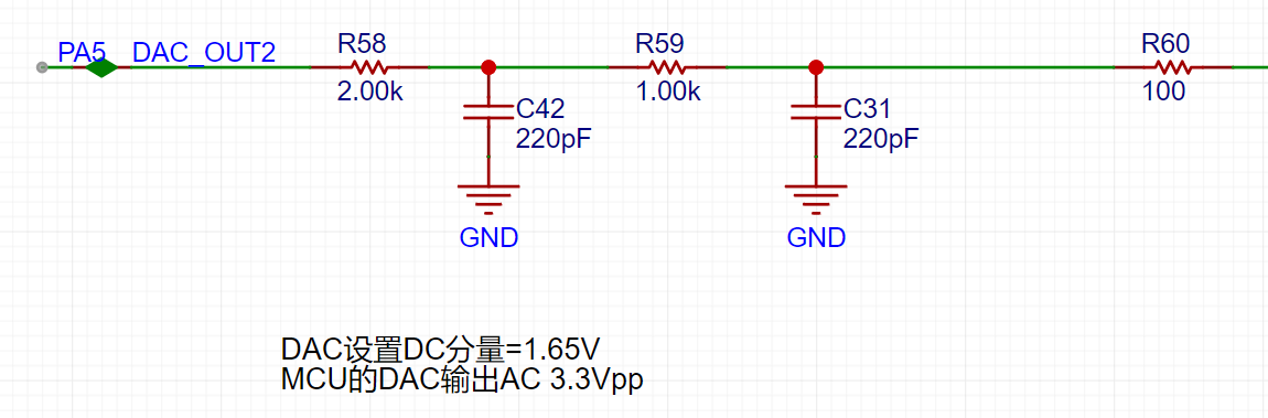
DAC_OUT2: The DC reference level, output through the STM32H750's internal DAC2 configuration.
Analog output channel introduction:
This includes signal conditioning implemented with resistor voltage dividers and operational amplifiers, and a square wave output implemented with a comparator (for triggering and frequency measurement).
The STM32H750's DAC1 output ranges from 0-3.3V.
A second-order RC filter implements a low-pass filter function.
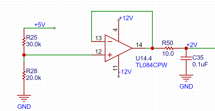
A resistor voltage divider and buffer convert the 5V input to a low-impedance 2V output, which is then amplified by -5 times for signal shifting.

The output amplifier performs two functions: first, it amplifies the non-inverting input by 6 times; second, it shifts the amplified signal by 6 times by -10V before outputting it, calculated as Vo = -10 + 6 * Vi.
A voltage divider network is used to achieve better results when outputting small signals using analog circuit voltage division.
Below, we will detail the calculations for the analog circuit:
Analog input channel calculation:
This section requires a basic understanding of operational amplifiers.
First, we need to recognize that when the VREF of the STM32H750 is powered by 3.3V, the input range of the STM32's ADC is 0-3.3V, while our input signal has a maximum range of ±15V. Therefore, we need to solve the problem of large signal input not being saturated. Let's solve an equation:
15*a+b = 3.3
-15*a+b = 0,
which gives a=0.11 and b=1.65.
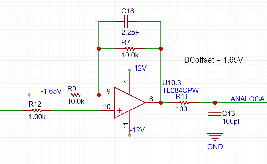
This means we need to attenuate the input signal to at least 0.11 times (approximately 1/9) and add 1.65V DC to meet the full-scale input of the ADC. Therefore, we use the following operational amplifier circuit. The resistor network achieves 1/20 attenuation, and the operational amplifier performs a 2x amplification and a 1.65V voltage shift, thus achieving 0.1INB + 1.65V.
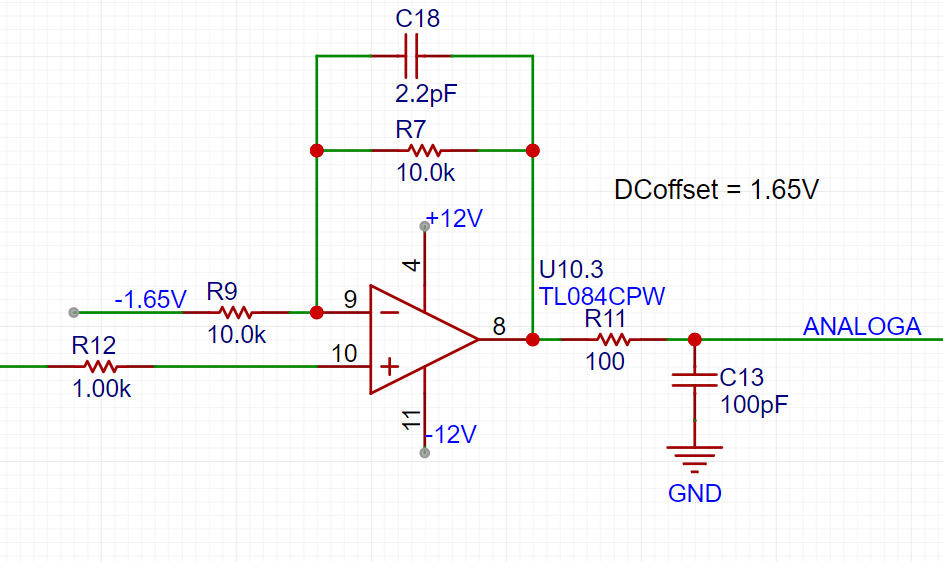
We can use the superposition theorem to analyze this circuit. First, when analyzing the contribution of the input signal INB to the output Vo, we ground the other voltage source in the circuit, -1.65V. This way, the input signal is divided to 1/20 after passing through R14 and R18, and then amplified by a factor of 2 by the non-inverting amplifier circuit. The overall gain of the input signal is 1/10. When analyzing the contribution of -1.65V to the output, we ground the input signal AIN, and the amplification factor of -1.65V is -1. Therefore, we obtain the output Vo = -1.65V * (-1) + AIN/10 = 1.65V + AIN/10.
The -1.65V above is obtained from -12V through a resistor divider and buffer.

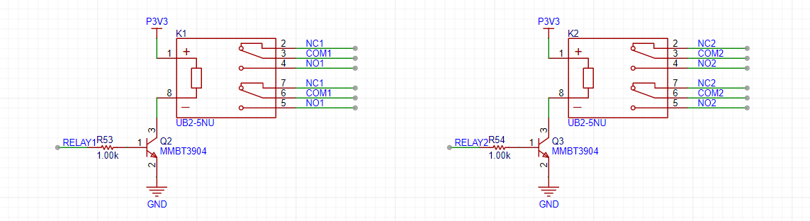
This circuit solves the problem of matching the ±15V input to the ADC's 0-3.3V input range. We also need to consider accurate sampling even with small input signals. For example, a 10mV signal will attenuate to 1mV after passing through this circuit. To maximize the signal-to-noise ratio of the input signal, we add a switching mode to the analog front-end. When acquiring small signals, the switch selects the direct input of INB to the non-inverting input of the op-amp, instead of selecting the attenuated signal from INB. This ensures the signal entering the ADC is as large as possible. Combined with a 16-bit ADC, this ensures accurate and reliable sampling results.

As shown in the diagram, we add a signal switch (relay or manual switch) after the 1M ohm input voltage divider resistor to select whether INB enters the op-amp's non-inverting input directly or after being divided by 1/20. Both methods result in a 1M ohm input impedance for INB. When we need to acquire small signals, we can toggle the switch to use the direct input for more accurate measurement results.
We can calculate that when the direct input is selected, Vo = 2AIN + 1.65, and when the attenuation input is selected, Vo = AIN/10 + 1.65.
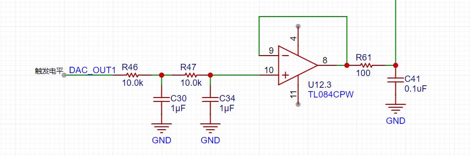
Analog output channel calculation:
When the VREF of the STM32H750 is powered by 3.3V, the output range of the internal DAC is 0-3.3V. To achieve the ±10V output required in the problem, we need to solve the following equations:
0*a + b = -10V
3.3*a + b =
Solving for 10V , we get a=6.06 and b=-10
, which allows us to design the following circuit:

In the diagram above, the 0-3.3V signal output from the STM32H750's internal DAC is filtered by a low-pass filter and then input to the non-inverting input of the TL082, forming a non-inverting amplifier with a gain of 6. The amplified waveform is 0-19.8V. Then, utilizing the -5x amplification capability of the TL082's inverting amplifier section, we amplify the +2V obtained from the 5V voltage divider to -10V, and superimpose this -10V with the 0-19.8V signal from the non-inverting amplifier to obtain an output of approximately ±10V. The calculation formula is: Vout = 6*Vin -10.
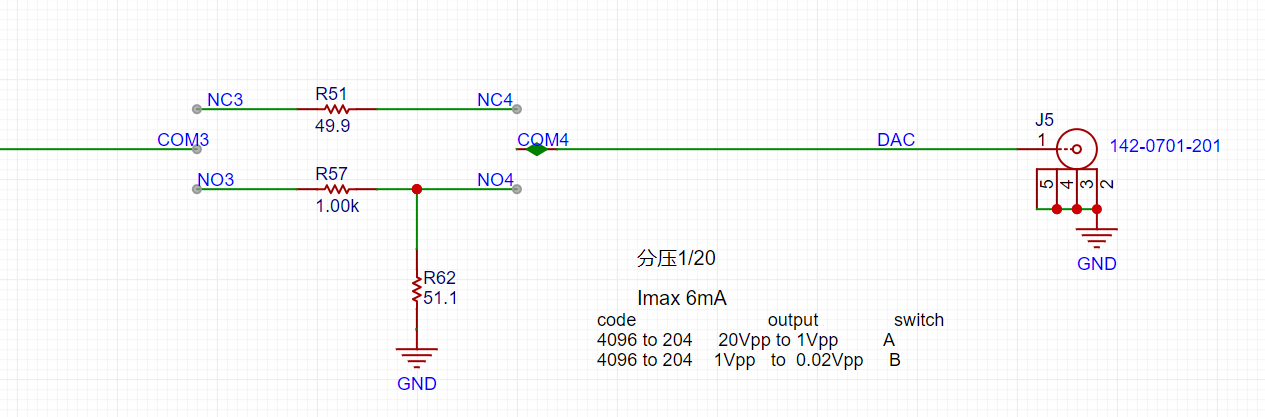
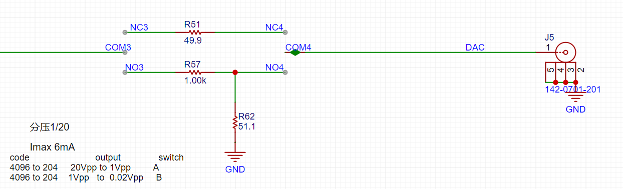
Similar to ADCs, the resolution of a DAC is crucial for achieving a signal source output covering ±10mV to ±10V while balancing a large signal range and small signal precision. The H750's DAC is 12-bit, with a full-scale output (using all 4096 code values) of ±10V. When reducing the DAC code value to output a small signal, to achieve a 7-bit voltage resolution (128 vertical points), the waveform must be attenuated by 128/4096 = 1/32. This translates to an output voltage range of ±10V/32 = ±0.3215V. For signals smaller than ±0.3125V, further reducing the code value results in insufficient DAC resolution, leading to noticeable waveform steps. Therefore, we use analog voltage division. When outputting signals smaller than ±0.3125V, a switching resistor divider attenuates the waveform by 1/20, ensuring sufficient voltage resolution for small signals. Meanwhile, the combination of R57 and R62 makes the output resistance of the circuit 50Ω at 1/20 attenuation, and R5 makes the output resistance of the circuit 50Ω at x1.
Comparator circuit:
To implement the trigger function and frequency counter function, we designed two comparator channels on the board to convert the waveforms of the two analog input channels before entering the ADC into square wave signals for use as timer inputs of H750. The reason for using the waveforms before entering the ADC for comparison is that the waveforms entering the ADC have been conditioned by the front-end analog circuit and have fallen within the known 0-3.3V range, making the comparison threshold of the comparator easier to design.
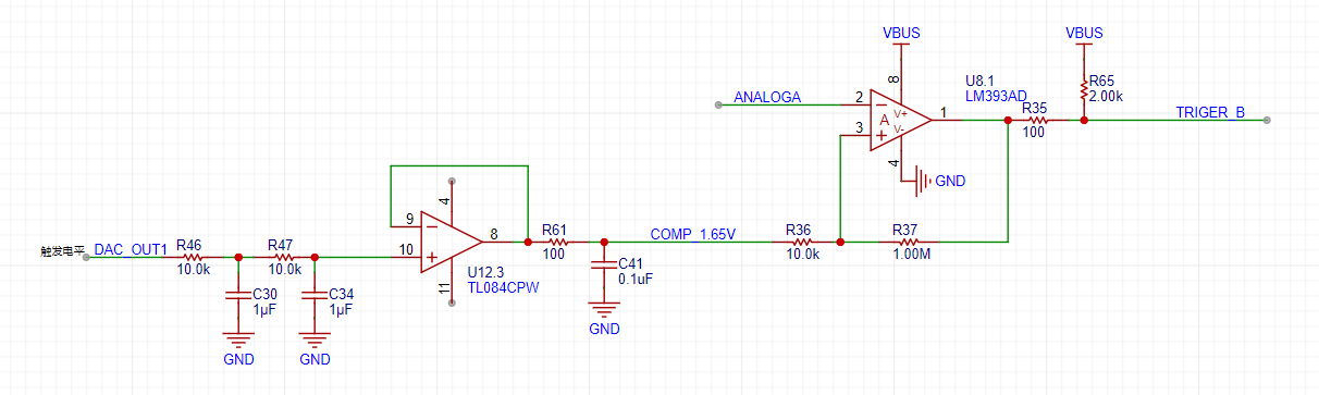
As shown in the figure above, H750 uses the internal DAC2 to output a 0-3.3V DC to compare with the waveform of channel 2 before entering the ADC, converting the waveform of channel 2 into a square wave. In this way, the timer function of H750 can use the square wave signal for interrupt processing and timer capture processing.
This oscilloscope & signal source has two input channels with an input voltage range of ±15V; and one output channel that can output sine waves, triangle waves, and square waves, with adjustable output frequency and amplitude.
The oscilloscope's two input ports meet the following requirements:
±10V dual-channel 2MHz sampling frequency or higher, 20kHz bandwidth. Sine wave peak-to-peak measurement error less than 5%.
Range switching via a knob.
Smooth triggering with no noticeable slippage.
Measurement frequency error no greater than 5%.
The signal source output port meets the following requirements:
When outputting ±4V 20kHz square wave, triangle wave, and sine wave, the peak-to-peak error of the waveform is no greater than 15%.
Screen link in the project:
https://item.taobao.com/item.htm?spm=a1z09.2.0.0.493e2e8dDj6cbx&id=721174513880
Thanks to JLCPCB!
Thanks to the experts in the group who answered my questions!
Thanks to Hardwood Classroom!
I learned a lot from replicating this project!
Looking forward to the next training camp!
The revised test video is as follows:

3DShell_PCB5 Oscilloscope.zip
Gerber_PCB5_oscilloscope_2023-11-13.zip
Oscilloscope Test.mp4
PDF_Replica of a Dual-Channel Oscilloscope Based on STM32H750VBT6.zip
Altium replica of a dual-channel oscilloscope based on STM32H750VBT6.zip
PADS_Replica of a Dual-Channel Oscilloscope Based on STM32H750VBT6.zip
BOM_Replica of a Dual-Channel Oscilloscope Based on STM32H750VBT6.xlsx
97031
Digital oscilloscope
This is a simple replica oscilloscope, only capable of using...
* 1. Project Function Introduction:
A simple oscilloscope. It displays sine waves up to 50kHz and outputs triangular, rectangular, and sine waves via a DAC.
* 2. Project Attributes:
A replica of the original oscilloscope.
The layout is still being updated. This version has a poor layout and low terminal availability; it's currently being updated, just for verification purposes.
* 3. Open Source License:
GPL 3.0
* 4. Hardware Part:
Signal Conditioning Circuit Implementation:
We will first briefly introduce the analog input and output channels on the AFE03 board. We will then discuss the design and calculation methods in detail.
Analog Input Channel Introduction:
This includes signal conditioning implemented with resistor voltage dividers and operational amplifiers, and a square wave output implemented with a comparator (for triggering and frequency measurement).
INA, INB: The oscilloscope's input terminals. The pocket instrument outputs an analog signal connected here. A 1MΩ input impedance is achieved through a series resistor voltage divider, generating two selectable signals: one direct input and one attenuated to 1/20.
Gain: A selector switch that chooses either a direct signal or a signal attenuated to 1/20th of its input to the first-stage non-inverting amplifier. The non-inverting amplifier performs two functions: first, it amplifies the input signal at the non-inverting input by a factor of two; second, it shifts the amplified signal by 1.65V, calculated as Vo = 1.65 + 2*Vi. Therefore, the overall gain of the circuit is either 2 or 1/10.
AnalogA, AnalogB: The amplified and shifted analog signals from the non-inverting amplifier are connected to the STM32H750 development board and enter the H750's ADC.
TrigerA, TrigerB: The square wave signals generated by AnalogA, AnalogB, and the DC reference level (generated by one of the H750's DACs) after passing through a comparator, enter the STM32H750's timer for frequency measurement.
DAC_OUT2: The DC reference level, output through the STM32H750's internal DAC2 configuration.
Analog output channel introduction:
This includes signal conditioning implemented with resistor voltage dividers and operational amplifiers, and a square wave output implemented with a comparator (for triggering and frequency measurement).
The STM32H750's DAC1 output ranges from 0-3.3V.
A second-order RC filter implements a low-pass filter function.
A resistor voltage divider and buffer convert the 5V input to a low-impedance 2V output, which is then amplified by -5 times for signal shifting.
The output amplifier performs two functions: first, it amplifies the non-inverting input by 6 times; second, it shifts the amplified signal by 6 times by -10V before outputting it, calculated as Vo = -10 + 6 * Vi.
A voltage divider network is used to achieve better results when outputting small signals using analog circuit voltage division.
Below, we will detail the calculations for the analog circuit:
Analog input channel calculation:
This section requires a basic understanding of operational amplifiers.
First, we need to recognize that when the VREF of the STM32H750 is powered by 3.3V, the input range of the STM32's ADC is 0-3.3V, while our input signal has a maximum range of ±15V. Therefore, we need to solve the problem of large signal input not being saturated. Let's solve an equation:
15*a+b = 3.3
-15*a+b = 0,
which gives a=0.11 and b=1.65.
This means we need to attenuate the input signal to at least 0.11 times (approximately 1/9) and add 1.65V DC to meet the full-scale input of the ADC. Therefore, we use the following operational amplifier circuit. The resistor network achieves 1/20 attenuation, and the operational amplifier performs a 2x amplification and a 1.65V voltage shift, thus achieving 0.1INB + 1.65V.
We can use the superposition theorem to analyze this circuit. First, when analyzing the contribution of the input signal INB to the output Vo, we ground the other voltage source in the circuit, -1.65V. This way, the input signal is divided to 1/20 after passing through R14 and R18, and then amplified by a factor of 2 by the non-inverting amplifier circuit. The overall gain of the input signal is 1/10. When analyzing the contribution of -1.65V to the output, we ground the input signal AIN, and the amplification factor of -1.65V is -1. Therefore, we obtain the output Vo = -1.65V * (-1) + AIN/10 = 1.65V + AIN/10.
The -1.65V above is obtained from -12V through a resistor divider and buffer.
This circuit solves the problem of matching the ±15V input to the ADC's 0-3.3V input range. We also need to consider accurate sampling even with small input signals. For example, a 10mV signal will attenuate to 1mV after passing through this circuit. To maximize the signal-to-noise ratio of the input signal, we add a switching mode to the analog front-end. When acquiring small signals, the switch selects the direct input of INB to the non-inverting input of the op-amp, instead of selecting the attenuated signal from INB. This ensures the signal entering the ADC is as large as possible. Combined with a 16-bit ADC, this ensures accurate and reliable sampling results.
As shown in the diagram, we add a signal switch (relay or manual switch) after the 1M ohm input voltage divider resistor to select whether INB enters the op-amp's non-inverting input directly or after being divided by 1/20. Both methods result in a 1M ohm input impedance for INB. When we need to acquire small signals, we can toggle the switch to use the direct input for more accurate measurement results.
We can calculate that when the direct input is selected, Vo = 2AIN + 1.65, and when the attenuation input is selected, Vo = AIN/10 + 1.65.
Analog output channel calculation:
When the VREF of the STM32H750 is powered by 3.3V, the output range of the internal DAC is 0-3.3V. To achieve the ±10V output required in the problem, we need to solve the following equations:
0*a + b = -10V
3.3*a + b =
Solving for 10V , we get a=6.06 and b=-10
, which allows us to design the following circuit:
In the diagram above, the 0-3.3V signal output from the STM32H750's internal DAC is filtered by a low-pass filter and then input to the non-inverting input of the TL082, forming a non-inverting amplifier with a gain of 6. The amplified waveform is 0-19.8V. Then, utilizing the -5x amplification capability of the TL082's inverting amplifier section, we amplify the +2V obtained from the 5V voltage divider to -10V, and superimpose this -10V with the 0-19.8V signal from the non-inverting amplifier to obtain an output of approximately ±10V. The calculation formula is: Vout = 6*Vin -10.
Similar to ADCs, the resolution of a DAC is crucial for achieving a signal source output covering ±10mV to ±10V while balancing a large signal range and small signal precision. The H750's DAC is 12-bit, with a full-scale output (using all 4096 code values) of ±10V. When reducing the DAC code value to output a small signal, to achieve a 7-bit voltage resolution (128 vertical points), the waveform must be attenuated by 128/4096 = 1/32. This translates to an output voltage range of ±10V/32 = ±0.3215V. For signals smaller than ±0.3125V, further reducing the code value results in insufficient DAC resolution, leading to noticeable waveform steps. Therefore, we use analog voltage division. When outputting signals smaller than ±0.3125V, a switching resistor divider attenuates the waveform by 1/20, ensuring sufficient voltage resolution for small signals. Meanwhile, the combination of R57 and R62 also makes the output resistance of the circuit 50Ω at 1/20 attenuation, and R5 makes the output resistance of the circuit 50Ω at x1.
Comparator circuit:
In order to realize the trigger function and frequency meter function, we designed two comparator channels on the board to convert the waveforms of the two analog input channels before entering the ADC into square wave signals for use as timer inputs of H750. The reason for using the waveforms before entering the ADC for comparison is that the waveforms entering the ADC have been conditioned by the front-end analog circuit and have fallen within the known 0-3.3V range, making the comparison threshold of the comparator easier to design.
As shown in the figure above, H750 uses the internal DAC2 to output a 0-3.3V DC to compare with the waveform of channel 2 before entering the ADC, converting the waveform of channel 2 into a square wave. In this way, the timer function of H750 can use the square wave signal for interrupt processing and timer capture processing.
*5. The software part
uses the open-source Hardwood Classroom code. *6. Please enter the content of
the BOM list ... Note: BOM list involved in the project. Please upload a screenshot of the BOM in this position. Please upload the detailed list in PDF format as an attachment. It is recommended to include the model number, brand, name, package, procurement channel, and intended use. The specific content and format should clearly express the project's composition. * 7. Demonstrate your project and record a video to upload: [#JLCIC# Hardwood Classroom Oscilloscope Replica Demo] https://www.bilibili.com/video/BV1rN411M7UF/?share_source=copy_web&vd_source=89d55fd33eb74796176a42d9f1555c62
PDF_DigitalOscilloscope.zip
Altium Digital Oscilloscope.zip
PADS_DigitalOscilloscope.zip
BOM_DigitalOscilloscope.xlsx
97032
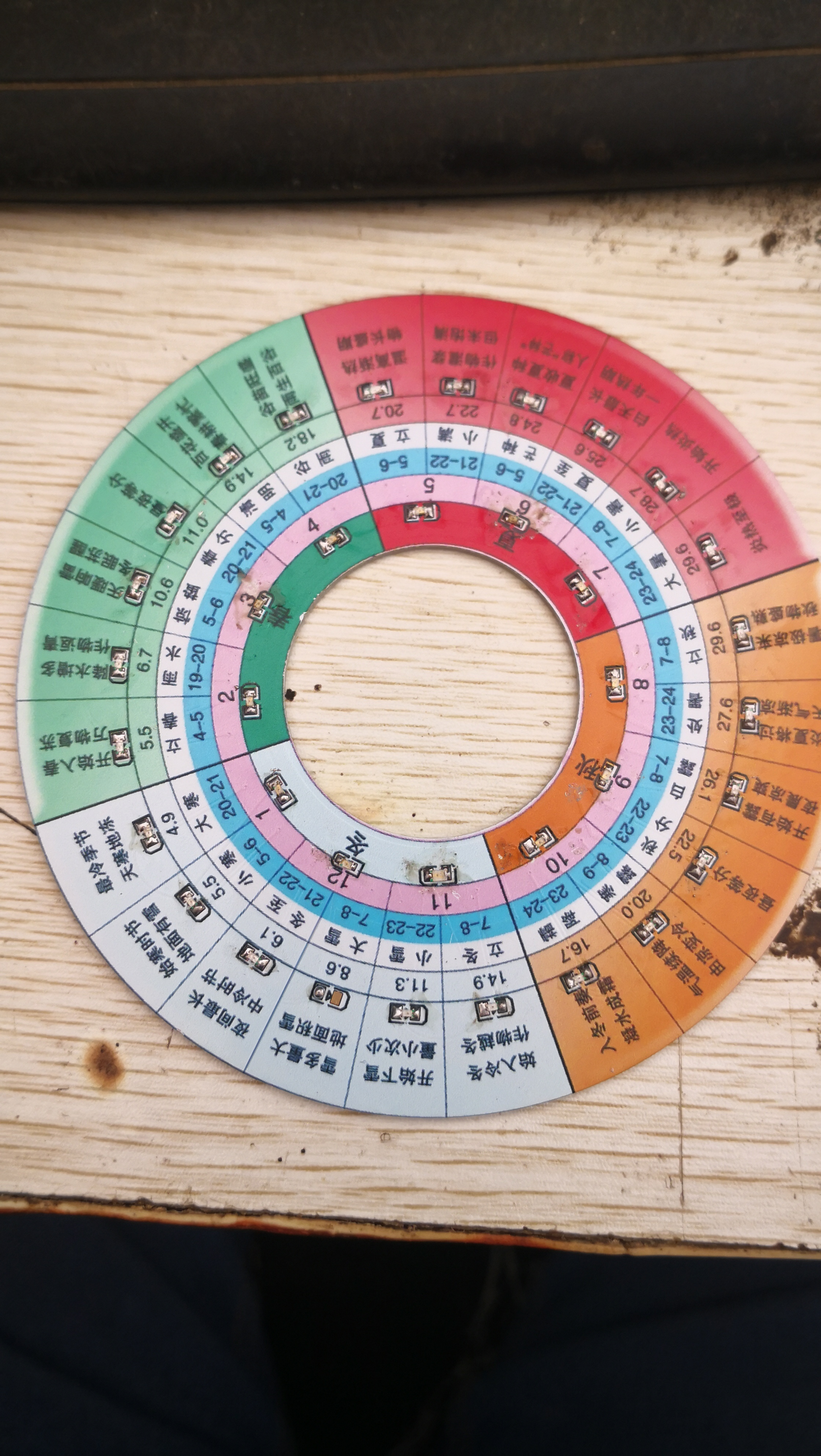
Solar Terms Spinner
I was making a 24 solar terms chart. I originally planned to use a control panel, but I happened to see a color printing promotion from XILCIC, so I made a 100mm diameter circle to test the waters first.
I was making a 24-solar-term clock. I initially planned to use a panel, but then I saw a color printing promotion from SICHUAN, so I made a 100mm diameter circle to test the waters.
This is just a modular panel,
cut in the middle. A stepper motor drives the middle section, connecting it to the outside. The central circular plate connects to the outer circle via spring contacts, forming a circuit loop that illuminates the LEDs.
This first version uses nine LEDs connected in series; later versions will use parallel connections to reduce voltage.


PDF_Solar Terms Spinner.zip
Altium_Solar Terms Turntable.zip
PADS_Solar Terms Turntable.zip
BOM_Solar Terms Turntable.xlsx
97033
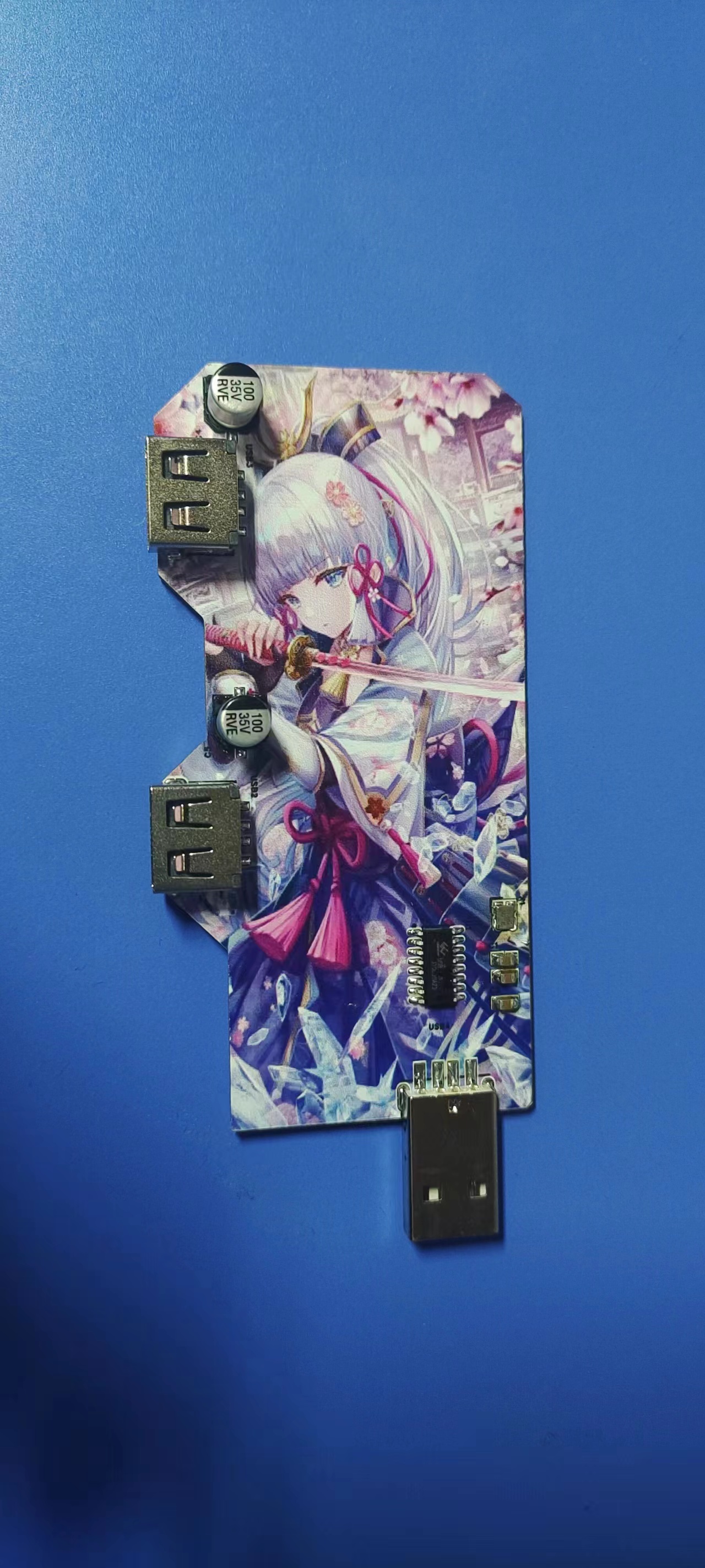
Expanding Dock (Color Printing Submission)
This project is a port replicator, or docking station, created in response to a design competition for JLCPCB color screen printing and based on my own specific needs.
A docking station, also known as a port replicator, is an external device designed specifically for laptops. By replicating or even expanding the ports of a laptop, it allows for convenient one-stop connection between the laptop and multiple accessories or external devices (such as power adapters, network cables, mice, external keyboards, printers, and external monitors).
Next, I will explain the function and characteristics of the components based on the schematic diagram.
First, let's look at the chip section.

The device with the reference number X1 is NX3225SA-12MHz-STD-CSR-6, which is a passive crystal oscillator. Here are some concepts we need to know:
Crystal is short for Crystal Resonator, also known as a passive crystal. It generally utilizes the piezoelectric effect of quartz crystals to generate a high-precision oscillation frequency. Passive crystals require capacitors and resistors to oscillate.
An active crystal oscillator is short for Crystal Oscillator. Active crystal oscillators integrate the oscillation circuit internally and can operate normally without the need for additional external components, but they require an external power supply.
A passive crystal oscillator (crystal) is mainly composed of a quartz crystal, a base, a casing, silver paste, and silver. Essentially, it's a quartz crystal resonator that utilizes the piezoelectric effect of quartz crystals to generate a high-precision oscillation frequency. A passive crystal oscillator has two pins, is non-polarized, and requires a clock circuit to generate an oscillation signal; it cannot oscillate on its own and is therefore a passive component.
Passive crystal oscillators require matching capacitors.
We use passive crystal oscillators to generate frequency for our circuits. We connect two 10uF capacitors to the passive crystal oscillator to form a circuit, enabling it to function.
The chip we use is the SL2.1A.
The SL2.1A is a highly integrated, high-performance, low-power USB 2.0 hub controller chip. This chip uses STT technology, a single power supply, and a 5V supply voltage. It internally integrates a 5V to 3.3V converter, requiring only an external power supply filter capacitor. The chip has a built-in reset circuit, and its low-power technology makes it even more outstanding.

The middle two pins of the male connector of the main interface are configured as the USB uplink DP signal and USB uplink DM signal of SL2.1A, respectively. A 10uF capacitor is also included in the main interface circuit for resonance and filtering.
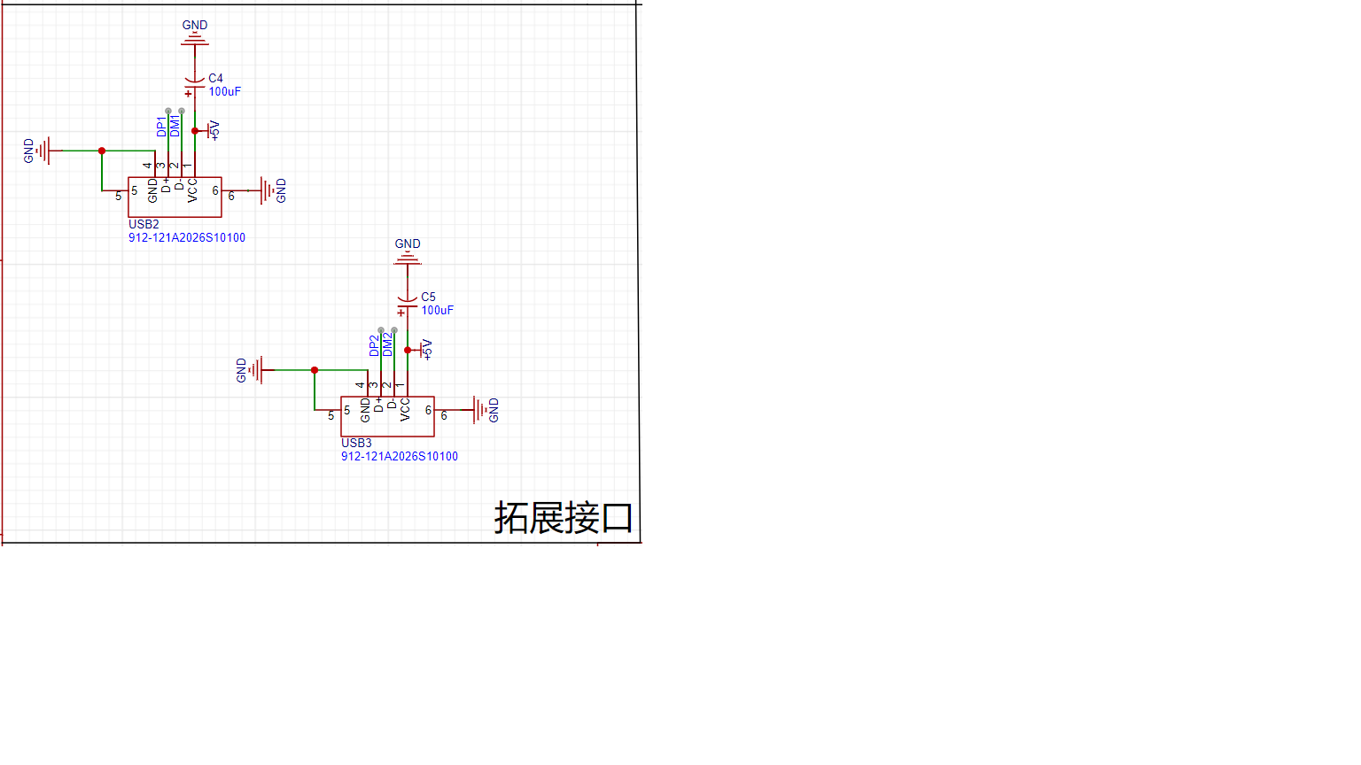
The middle two pins of the two female connectors of the expansion interface are configured as the USB DP signal and USB DM signal of Downlink Port 1 and Downlink Port 2, respectively. A 100uF capacitor is connected to each of the two female connectors for filtering.
This is the relevant architecture of this project. Welcome friends and teachers to exchange ideas, provide guidance, and ask questions.
Below is a physical demonstration.

888cb255fa5c4ac1a978f594ade690a2.mp4
WeChat image_20231123113150.jpg
WeChat image_20231123113143.jpg
PDF_Expansion Dock (Color Print Collection).zip
Altium_Extension Dock (Color Print Collection).zip
PADS_Extension Dock (Color Printing Collection).zip
BOM_Expansion Dock (Color Printing Submission).xlsx
97035
BM3451 3-cell battery protection board
BM3451 3-cell battery protection
This is a direct copy of the BM3451 [Four-Series Lithium Battery Protection Board] - JLCPCB EDA Open Source Hardware Platform (oshwhub.com) original author, with modifications to the LED section. The number of MOSFETs has been reduced to two, and the current sensing resistor has been changed to 10mΩ.
The maximum current calculation method is 0.1V/R18=Imax.
Overcharge and over-discharge protection voltages should be selected according to the datasheet. This project uses the BM3451BHDC-T28A as the main chip, for lithium iron phosphate batteries.
Overcharge protection is 3.65V,
over-discharge protection is 2.35V,
maximum current (200ms) is 10A (default),
maximum current (20ms) is 30A (default),
and short circuit protection is 600us (maximum).
Please solder the battery pack according to the board's instructions:
1 is total negative , 2
is the first series positive
, 3 is the second series positive,
and 4 is total positive.
To achieve a full 10A current, please add more solder!
PDF_BM3451 3-cell battery protection board.zip
Altium_BM3451 3-cell battery protection board.zip
PADS_BM3451 3-cell battery protection board.zip
BOM_BM3451 3-cell battery protection board.xlsx
97040
Automotive Ethernet TE Connectivity and Rosen e6s20a Adapter Board
Rosenberger E6S20A-40MT5-Z and Tyco 2304372-1 adapters
are respectively converted to 2-pin terminals.
Rosenberger E6S20A-40MT5-Z and Tyco 2304372-1 adapters are respectively converted to 2-pin terminals.
PDF_Automotive Ethernet TE Connector and Rosen e6s20a Adapter Board.zip
Altium_Automotive Ethernet TE Connector and Rosen e6s20a Adapter Board.zip
PADS_Automotive Ethernet TE Connector and Rosen e6s20a Adapter Board.zip
BOM_Automotive Ethernet Tyco and Rosen e6s20a Adapter Board.xlsx
97042
electronic


 京公网安备 11010802033920号

 CAT1021YE-28TE13


