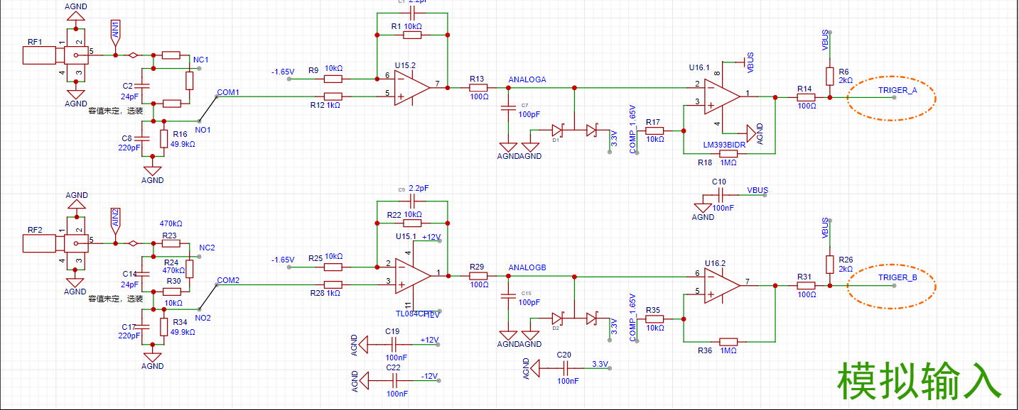
 INA, INB: Input terminals of the oscilloscope. The STM32H750VBT6 outputs analog signals that connect here. A 1MΩ input impedance is achieved through a series resistor voltage divider. Direct connection or 1/20 attenuation can be selected.
  AnalogA, AnalogB: The amplified and shifted analog signals from the non-inverting amplifier are connected to the STM32H750 development board and enter the H750's ADC.
  TrigerA, TrigerB: AnalogA, AnalogB, and the DC reference level (generated by one of the H750's DACs) pass through a comparator to generate a square wave signal, which enters the STM32H750's timer for frequency measurement.
 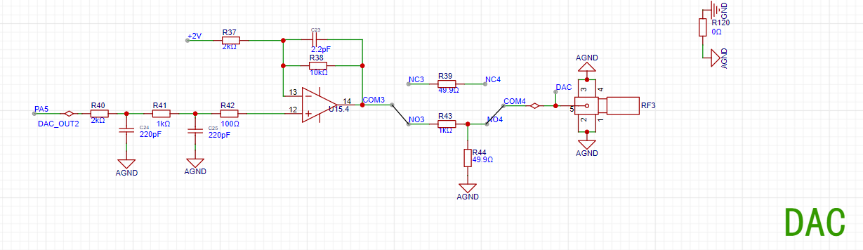 DAC_OUT2: DC reference level, output via the internal DAC2 configured by the STM32H750.
 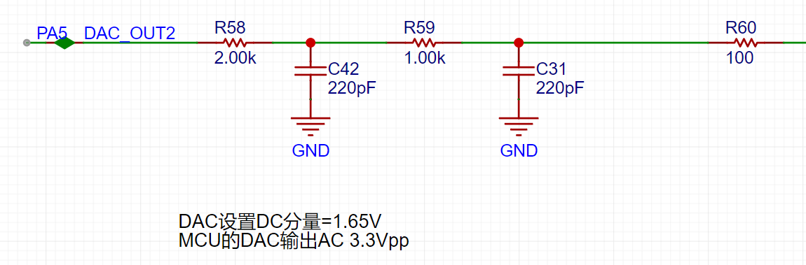 The STM32H750's DAC1 output ranges from 0-3.3V.
 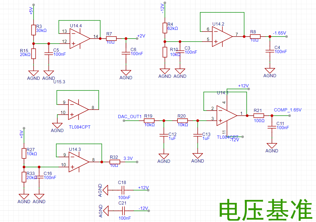 A resistor divider and buffer convert the 5V input to a low-impedance 2V output, which is then amplified by -5 times for signal shifting.
  The output amplifier performs two functions: first, it amplifies the non-inverting input by 6 times; second, it shifts the amplified signal by -10V before outputting it, calculated as Vo = -10 + 6 * Vi.
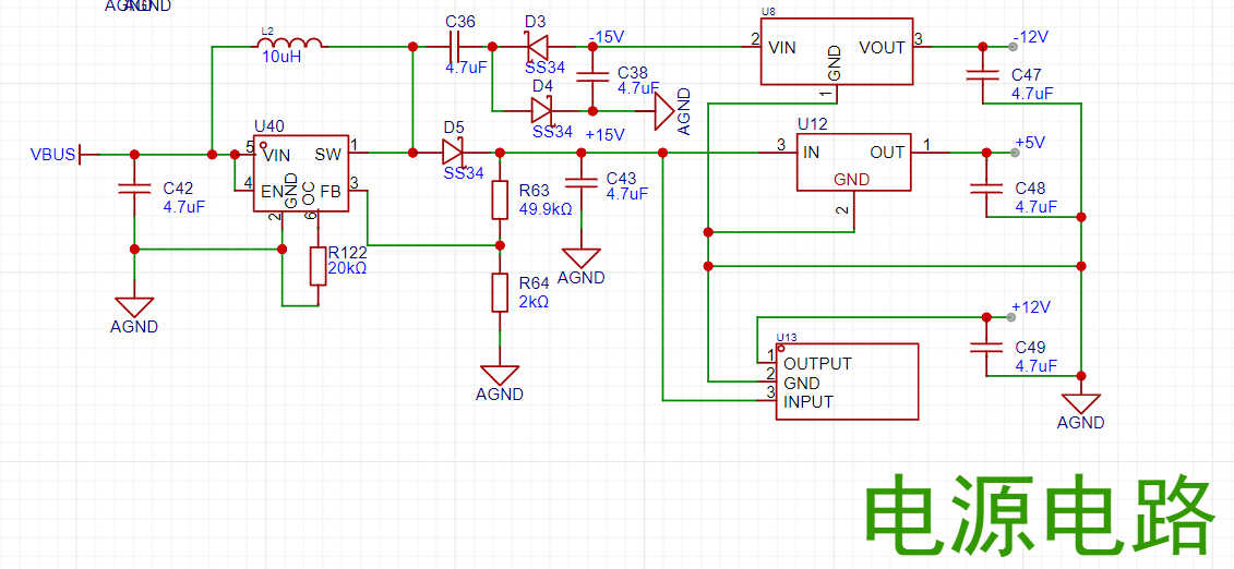 The power supply section used a domestic MT3608L, but during testing, it worked normally when the input voltage was below 5V. However, above 5V, the power supply was directly output most of the time, and the power chip did not work. Many methods were tried without success, and finally, the MT3608 was replaced, and the GND feedback resistor was removed.
All reference designs on this site are sourced from major semiconductor manufacturers or collected online for learning and research. The copyright belongs to the semiconductor manufacturer or the original author. If you believe that the reference design of this site infringes upon your relevant rights and interests, please send us a rights notice. As a neutral platform service provider, we will take measures to delete the relevant content in accordance with relevant laws after receiving the relevant notice from the rights holder. Please send relevant notifications to email: bbs_service@eeworld.com.cn.
It is your responsibility to test the circuit yourself and determine its suitability for you. EEWorld will not be liable for direct, indirect, special, incidental, consequential or punitive damages arising from any cause or anything connected to any reference design used.
Supported by EEWorld Datasheet
EEWorld
subscription
account

EEWorld
service
account

Automotive
development
community

Robot
development
community

About Us Customer Service Contact Information Datasheet Sitemap LatestNews


Room 1530, 15th Floor, Building B,
No.18 Zhongguancun Street,
Haidian District,
Beijing, Postal Code: 100190
China
Telephone: 008610 8235 0740
 京公网安备 11010802033920号

 SBC-15


