Implementation of Signal Conditioning Circuit:
We will first briefly introduce the analog input and output channels on the AFE03 board, and then discuss the design and calculation methods in detail later.
Analog Input Channel Introduction:
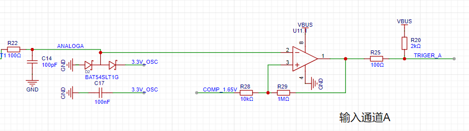
This includes signal conditioning implemented with resistor dividers and operational amplifiers, and a square wave output implemented with a comparator (for triggering and frequency measurement).

Analog Output Channel Introduction:
This includes signal conditioning implemented with resistor dividers and operational amplifiers, and a square wave output implemented with a comparator (for triggering and frequency measurement).
A second-order RC filter is used to implement a low-pass filter function.
Next, we will discuss the calculations for the analog circuit in detail: Analog Input Channel Calculation:
This section requires a basic understanding of operational amplifiers.
First, we need to recognize that when the VREF of the STM32H750 is powered by 3.3V, the input range of the STM32's ADC is 0-3.3V, while our input signal has a maximum range of ±15V. Therefore, we need to solve the problem of large signal input not being saturated. Let's solve an equation:
15*a+b = 3.3
-15*a+b = 0,
which gives a=0.11 and b=1.65.
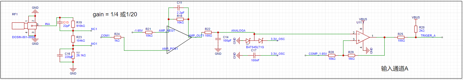
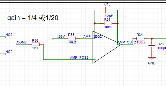
This means we need to attenuate the input signal to at least 0.11 times (approximately 1/9) and add 1.65V DC to meet the full-scale input of the ADC. Therefore, we use the following operational amplifier circuit. The resistor network performs 1/20 attenuation, and the operational amplifier achieves a 2x amplification and a 1.65V voltage shift, thus achieving 0.1INB + 1.65V.
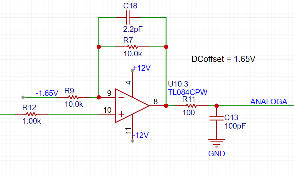
The -1.65V above is obtained from -12V through a resistor divider and a buffer.

We can calculate that when the direct input is selected, Vo = 2AIN + 1.65, and when the attenuation input is selected, Vo = AIN/10 + 1.65.
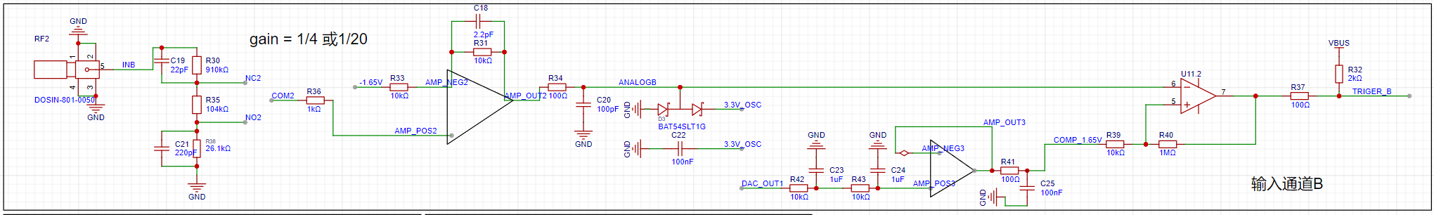
Analog output channel calculation:
When the VREF of the STM32H750 is powered by 3.3V, the output range of the internal DAC is 0-3.3V. To achieve the ±10V output required in the problem, we need to solve the following equations:
0*a + b = -10V
3.3*a + b =
Solving for 10V , we get a=6.06 and b=-10
, which allows us to design the following circuit:

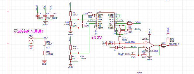
Comparator Circuit:
To implement the trigger and frequency meter functions, we designed two comparator channels on the board. These channels convert the waveforms of the two analog input channels before entering the ADC into square wave signals for use as timer inputs for the H750. The reason for using the waveforms before entering the ADC for comparison is that the waveforms entering the ADC, after being conditioned by the front-end analog circuit, fall within the known 0-3.3V range, making the comparator's comparison threshold easier to design.
video_20231117_164542.mp4
video_20231117_160851.mp4
IMG_20231117_184358.jpg
PDF_【Replica】【Hardwood Classroom】Oscilloscope Instruments.zip
Altium_【Replica】【Hardwood Classroom】Oscilloscope Instruments.zip
PADS_【Replica】【Hardwood Classroom】Oscilloscope Instruments.zip
BOM_【Replica】【Hardwood Classroom】Oscilloscope Instruments.xlsx
97095
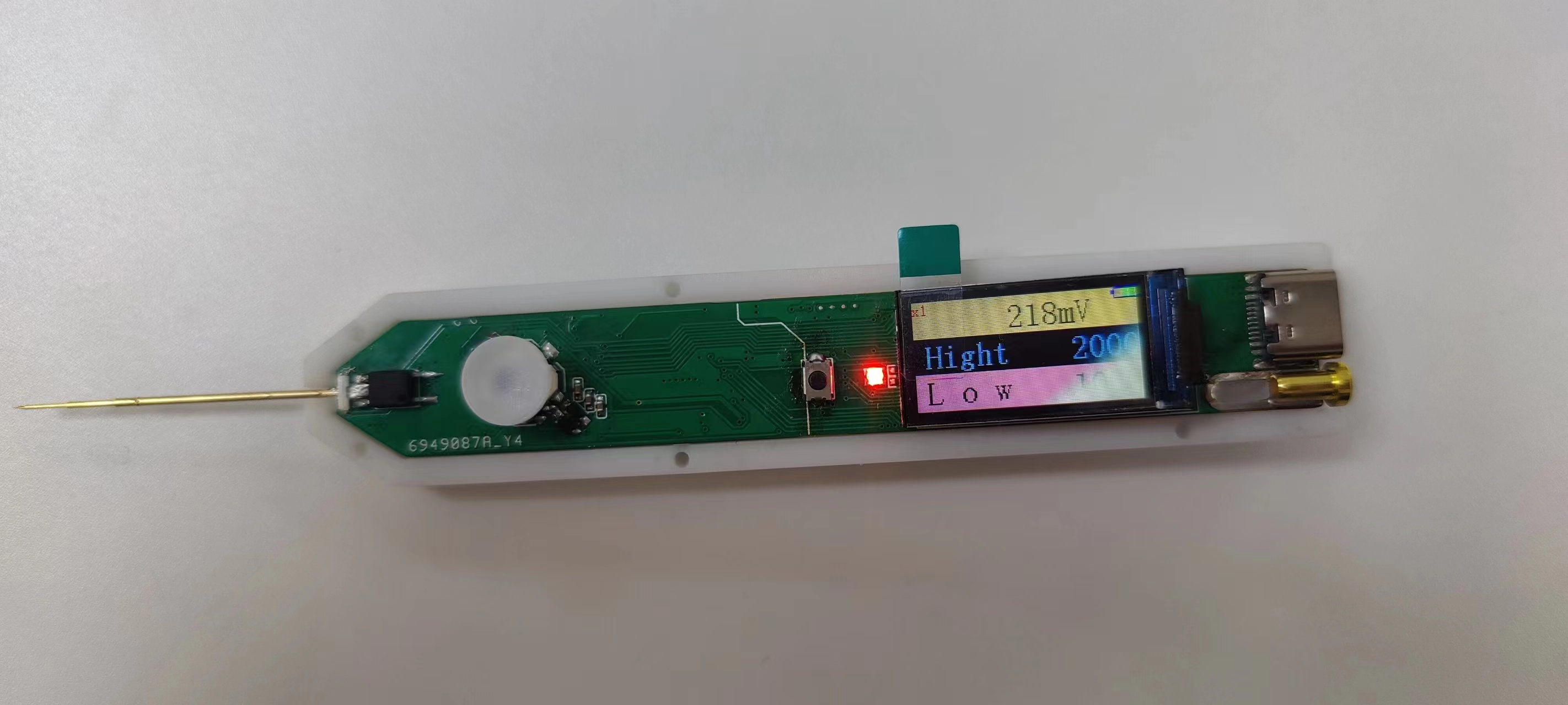
CW32 Multifunctional Testing Pen
This is a portable multi-functional test pen designed with the CW32F030C8T6 as the main controller, featuring functions such as voltage measurement, continuity measurement, diode detection, and signal output.
CW32 Multifunctional Test Pen
- Portable Multifunctional Test Pen Design Based on CW32F030
"Point
" refers to the pen's operation method; simply tap a node on the circuit board to perform a test. "Crystal" refers to a transistor, generally referring to all electronic circuits.
1. Power and Battery Management
1.1 Charge and Discharge Management
In the charging IC section, I chose the commonly used TP4057 as the main controller. The power input uses the most common Type-C interface. Although a 6-pin interface would be sufficient in this project, considering the project's expandability, a 16-pin interface was chosen. The SBU1 and SBU2 pins of the Type-C interface were used for expansion board connections. The reason for not using D+ and D- as expansion lines is that the device's output signal may cause the charger to misinterpret, resulting in an incorrect voltage and causing danger. This needs to be considered in the design.

2.1 CW32 Microcontroller Core System
The standard microcontroller core system configuration is omitted here because this project does not require a high-precision clock and low-speed crystal oscillator for long-term timing (it is drawn here, but set not to be transferred to PCB or imported into BOM, mainly so that it can be directly copied and used in other projects, primarily for CV engineers).

2.2 User Operation Input
The user operation part of this project uses a five-way joystick switch, which can be understood as equivalent to five ordinary button switches. Programming it is also done as ordinary buttons. "

Point Crystal"
: Point refers to the operation mode of the test pen; lightly touching a node on the circuit board performs a test; Crystal refers to transistor, generally referring to all electronic circuits.
1. Power and Battery Management
1.1 For charging and discharging management,
I chose the commonly used TP4057 as the main controller in the charging IC section. The power input uses the most common Type-C interface. Although a 6-pin interface would be sufficient for this project, a 16-pin interface was chosen for scalability. The SBU1 and SBU2 pins from the Type-C interface were used for expansion board connections. D+ and D- were not used for expansion circuitry because the device's output signal might cause the charger to misinterpret the signal, resulting in an incorrect voltage and potential danger. This needs to be considered in the design.
2.1 CW32 Microcontroller Core System:
Standard microcontroller core system configuration. Since this project does not require a high-precision clock and low-speed crystal oscillator for long-term timing, this part of the circuit is omitted (it is drawn here, but set not to be transferred to the PCB or imported into the BOM, mainly so that it can be directly copied and used in other projects, primarily for a CV engineer).
2.2 For convenient connection between the test
pen and a computer or mobile phone, I chose to use Bluetooth BLE technology for wireless data transmission.

"Point-to-Point Pen": "Point
" refers to the operation method of the test pen; lightly touching a node on the circuit board initiates the test. "Crystal" refers to a transistor, generally referring to all electronic circuits.
1. Power and Battery Management
1.1 Charge and Discharge Management
In the charging IC section, I chose the commonly used TP4057 as the main controller. The power input uses the most common Type-C interface. Although a 6-pin interface would be sufficient for this project, considering the project's expandability, a 16-pin interface was chosen. The SBU1 and SBU2 pins from the Type-C interface were used for expansion board connections. D+ and D- were not used as expansion lines because the device's output signal might cause the charger to misinterpret the signal, resulting in an incorrect voltage and potential danger. This needs to be considered in the design.
2.1 The CW32 microcontroller core system
is a standard microcontroller core system configuration. Since this project does not require a high-precision clock and low-speed crystal oscillator for long-term timing, this part of the circuitry is omitted (it is drawn here, but set not to be transferred to the PCB or imported into the BOM, mainly so that it can be directly copied and used in other projects, primarily for a CV engineer).
2.2 User Operation Input
The user operation part of this project uses a five-way joystick switch, which can be understood as equivalent to five ordinary button switches. Programming it is also done as ordinary buttons.
"Point Crystal": The operation method of the point crystal pen
; "Point" refers to the operation mode of the test pen, lightly touching a node on the circuit board to perform a test; "Crystal" refers to a transistor, generally referring to all electronic circuits
. 1. Power and Battery Management
1.1 For charging and discharging management,
I chose the commonly used TP4057 as the main controller in the charging IC section. The power input uses the most common Type-C interface. Although a 6-pin interface would be sufficient for this project, a 16-pin interface was chosen for scalability. The SBU1 and SBU2 pins from the Type-C interface were used for expansion board connections. D+ and D- were not used for expansion circuitry because the device's output signal might cause the charger to misinterpret the signal, resulting in an incorrect voltage and potential danger. This needs to be considered in the design.
2.1 CW32 Microcontroller Core System:
Standard microcontroller core system configuration. Since this project does not require a high-precision clock and low-speed crystal oscillator for long-term timing, this part of the circuit is omitted (it is drawn here, but set not to be transferred to the PCB or imported into the BOM, mainly so that it can be directly copied and used in other projects, primarily for a CV engineer).
2.3 Analog Front-End and Input/Output


Physical Verification:

test_pen-master.zip
PDF_CW32 Multifunctional Test Pen.zip
Altium_CW32 Multi-functional Test Pen.zip
PADS_CW32 Multifunctional Test Pen.zip
BOM_CW32 Multifunctional Test Pen.xlsx
97096
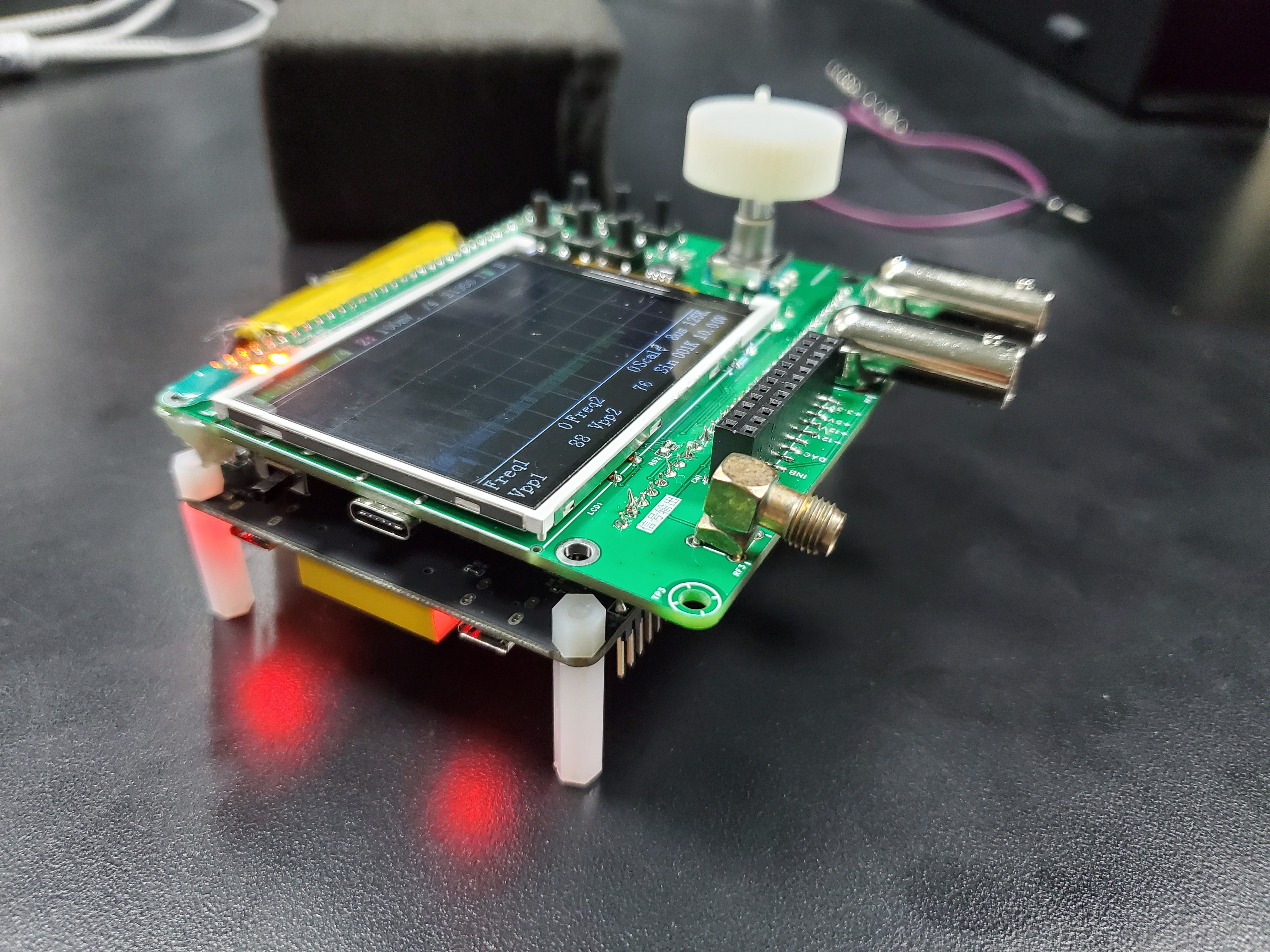
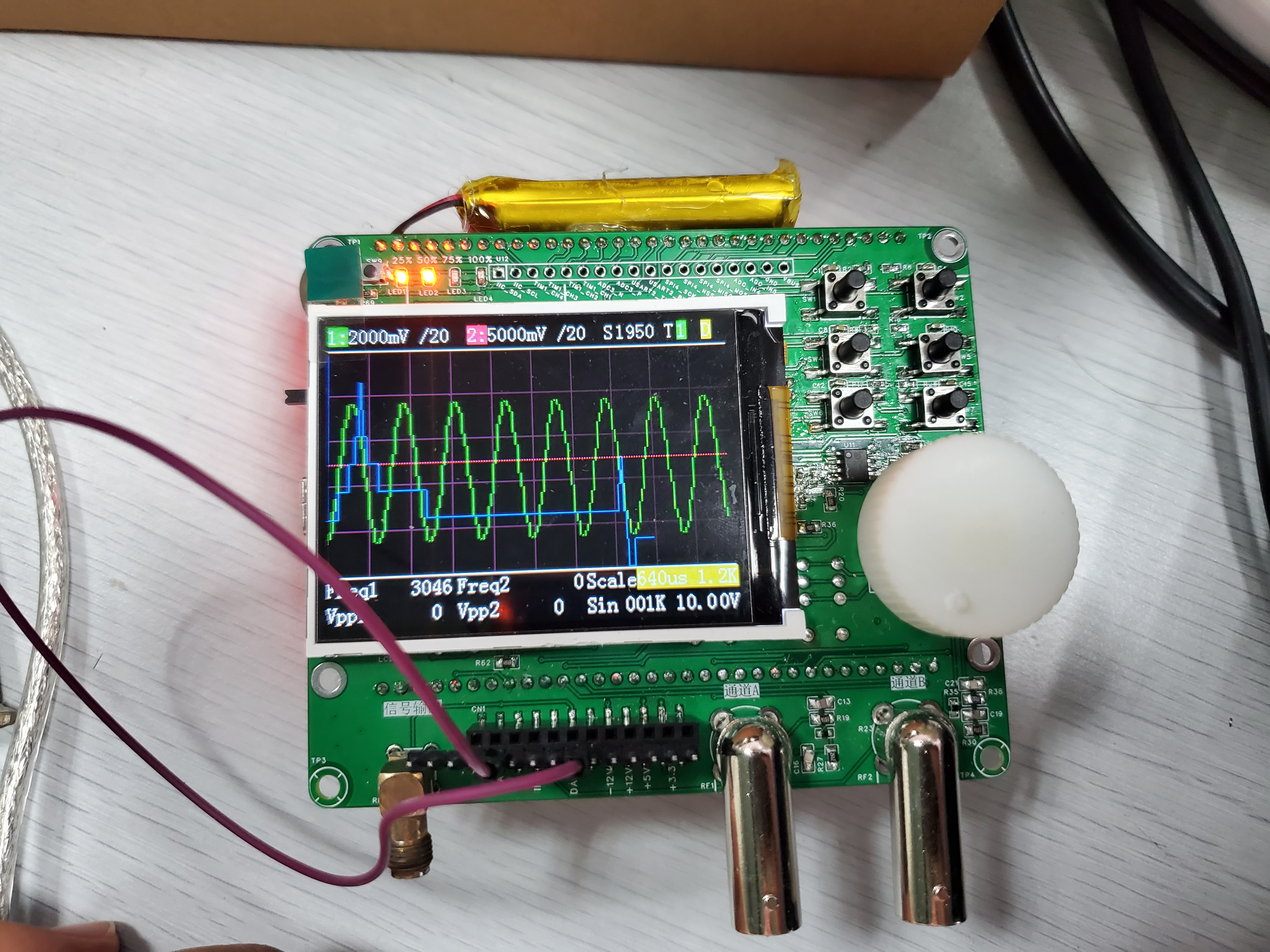
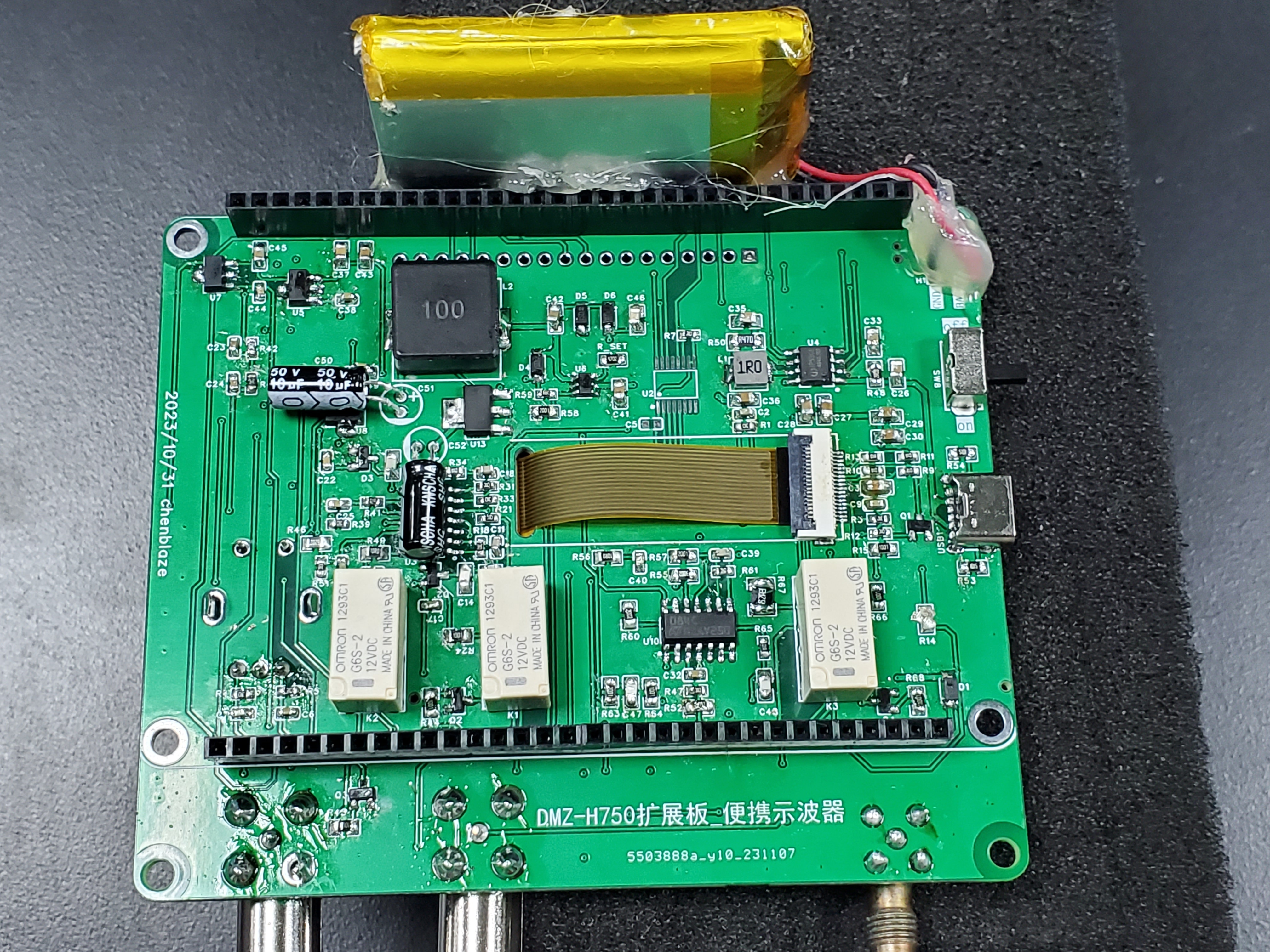
Simple Oscilloscope
This project is a secondary development based on the Hardwood Classroom open-source project with slight modifications. The main addition is a battery charging and discharging module, allowing it to be used without a power supply. Secondly, the voltage range of the analog front-end has been changed to ±33V.
Physical demonstration!
Note: This project is a secondary
development of the charging and discharging circuit based on the Hardwood Classroom open-source project (https://oshwhub.com/damihuang/AFE03).
The charging and discharging chip uses the IP5306, which supports direct USB 5V charging and directly boosts the battery discharge voltage to 5V, making it very convenient to use. Four external LEDs can indicate the battery's charging and discharging capacity.

Analog input channel introduction:
Includes signal conditioning implemented with resistor voltage dividers and operational amplifiers, and a square wave output implemented with a comparator (for triggering and frequency measurement).
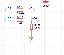
INA, INB: Oscilloscope input terminals. The pocket instrument sends an analog signal to this point. Here, a 1MΩ input impedance is achieved through a series resistor voltage divider, generating two selectable signals: one with 1/8 attenuation and the other with 1/40 attenuation.
Gain: A selector switch that chooses a signal attenuated by 1/8 or 1/40 to enter the first-stage non-inverting amplifier. The non-inverting amplifier performs two functions: first, it amplifies the input signal at the non-inverting input by a factor of two; second, it shifts the amplified signal by 1.65V, calculated as Vo = 1.65 + 2*Vi. Therefore, the overall gain of the corresponding circuit is 1/4 or 1/10.
AnalogA, AnalogB: The amplified and shifted analog signals are connected to the STM32H750 development board and enter the H750's ADC.
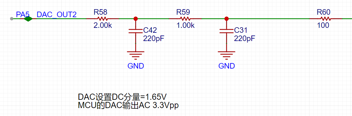
TrigerA, TrigerB: The square wave signals generated by AnalogA, AnalogB, and the DC reference level (generated by one of the H750's DACs) after passing through a comparator, enter the STM32H750's timer for frequency measurement.

DAC_OUT2: The DC reference level, output through the STM32H750's internal DAC2 configuration.
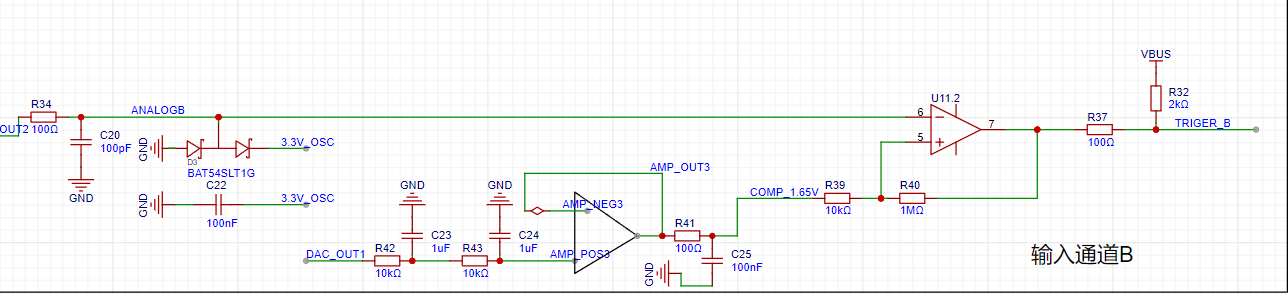
Analog Output Channel Introduction:
This includes signal conditioning implemented with resistor voltage dividers and operational amplifiers, and a square wave output implemented with a comparator (for triggering and frequency measurement).

The STM32H750's DAC1 output ranges from 0-3.3V.
A second-order RC filter implements a low-pass filter function.

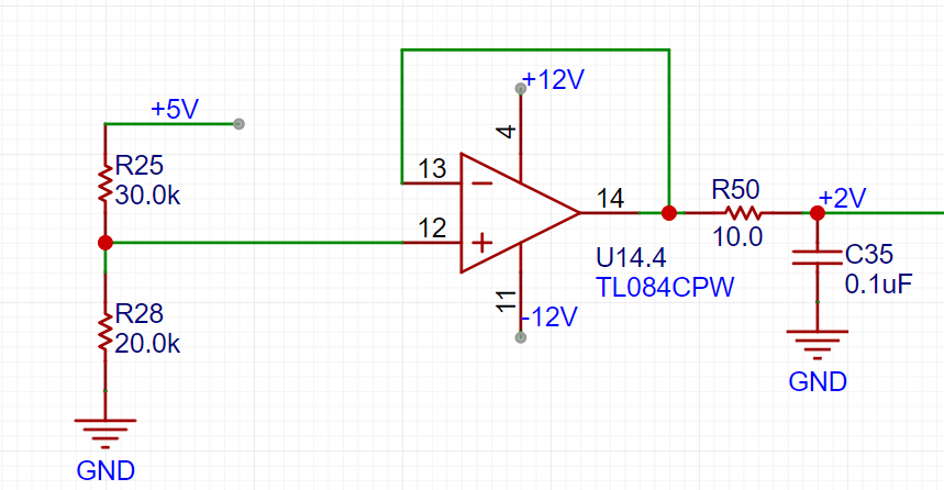
A resistor voltage divider and buffer convert the 5V input to a low-impedance 2V output, which is then amplified by -5 times for signal shifting.

The output amplifier performs two functions: first, it amplifies the non-inverting input by 6 times; second, it shifts the amplified signal by 6 times to -10V before outputting it, calculated as Vo = -10 + 6 * Vi.

A voltage divider network is used to achieve better results when outputting small signals using analog voltage division.
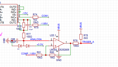
Comparator Circuit:
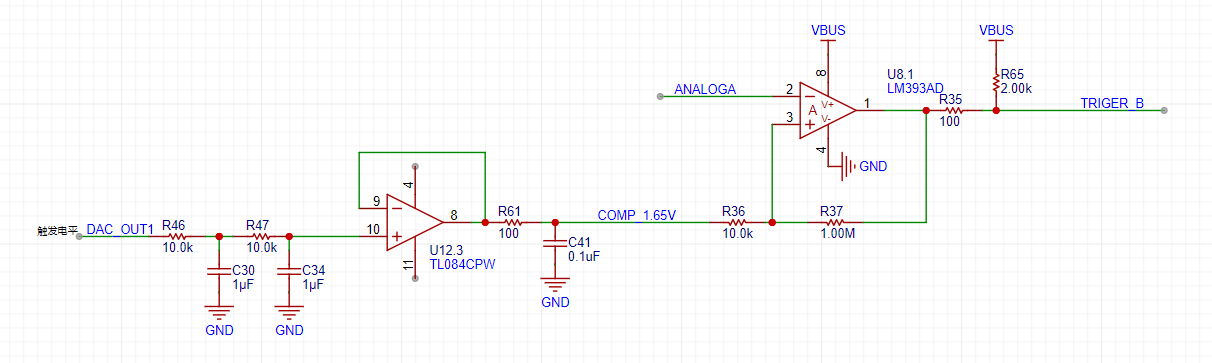
To implement triggering and frequency meter functions, we designed two comparator channels on the board. These channels convert the waveforms from the two analog input channels before they enter the ADC into square wave signals for use as timer inputs for the H750. The reason for using the waveform before it enters the ADC for comparison is that the waveform entering the ADC has been conditioned by the front-end analog circuitry to fall within the known 0-3.3V range, making the comparator's comparison threshold easier to design.
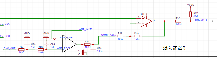
As shown in the diagram above, the H750 uses its internal DAC2 to output a 0-3.3V DC signal to compare with the waveform of channel 2 before it enters the ADC, converting the waveform of channel 2 into a square wave. This allows the H750's timer function to use the square wave signal for interrupt handling and timer capture processing.
8e9a1e50a6f6cbe7b9c5612fd544bbfc.mp4
PDF_Simple Oscilloscope.zip
Altium_SimpleOscilloscope.zip
PADS_Simple Oscilloscope.zip
BOM_Simple Oscilloscope.xlsx
97097
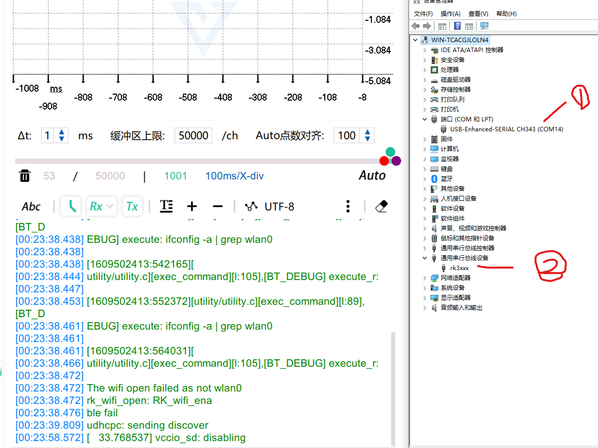
SoloLinker-A USB Adapter Board
SoloLinker-A Development Board USB and Serial One-Way Solution
While browsing Bilibili recently, I discovered the SoloLinker-A development board. It uses the RV1106 controller, starts at 39 RMB, and supports RGB screens. The demo showed incredibly smooth scrolling, making it seem like a great value, so I decided to buy it.
While waiting for delivery, I noticed in the official schematic that the board uses a 24-pin Type-C port that simultaneously receives USB and serial signals. Using a single data cable only connects to the USB signal, requiring a USB-to-serial adapter to receive the serial signal. Therefore, an adapter board is needed to separate these two signals.
The official serial adapter board does exist, but it requires three data cables to receive both USB and serial signals simultaneously, which is inefficient. This led me to this project.
My ideal adapter board has two key features: 1. Small size; 2. Simple wiring.
The hardware solution used in this project is: CH334P (USB HUB chip) + CH343P (USB to serial port chip). Both chips have very compact packages. The CH334 is a USB HUB chip that supports MTT, and compared to the older STT, it doesn't slow down when multiple devices are connected simultaneously. The CH334 is a high-performance USB to serial port chip with baud rates reaching the M level.
Precautions during replication:
1. Tantalum capacitors are used to prevent the power supply voltage from being pulled down when external devices are plugged in, causing the HUB chip to restart. Be careful not to reverse the polarity, otherwise the consequences will be severe.
2. Choose a board thickness of 1.0mm for board fabrication because the TYPEC male connector on the board is a clamp-type design, and 1.0mm is its limit. 0.8mm is not chosen because a 0.8mm four-layer board cannot be fabricated for free.
3. When soldering the Type-C male connector, the pins may tilt upwards after insertion. Use a hard object to press the pins down; otherwise, solder bridging will occur.
4. It is recommended to use solder paste and a hot air gun for soldering. This board is designed to be compact to minimize space, so be careful to avoid cold solder joints.
Finally, please give it a like to let me know you've been here; it's the greatest affirmation for me.
(Images of the adapter board,
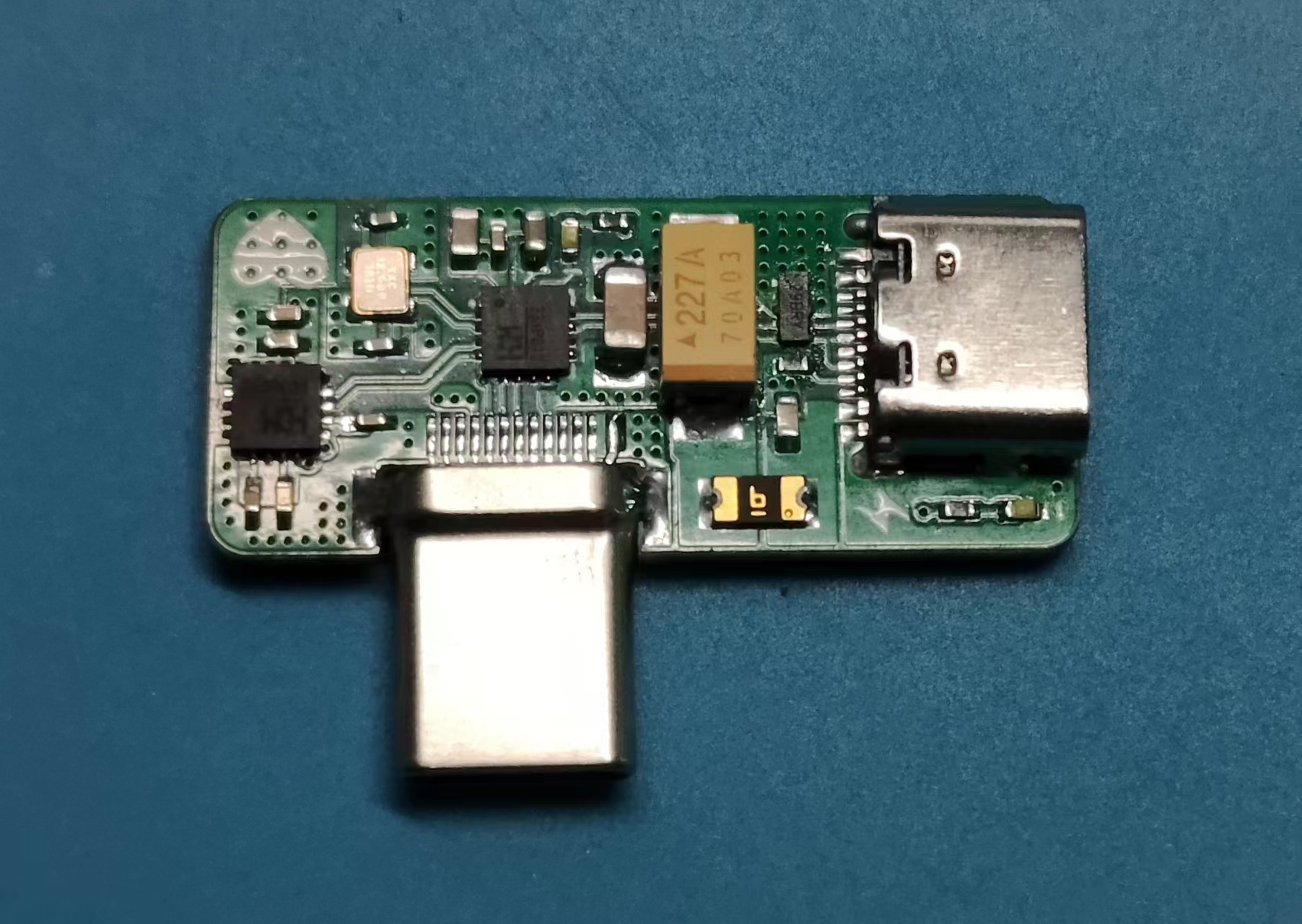
its connection to the development board, and its
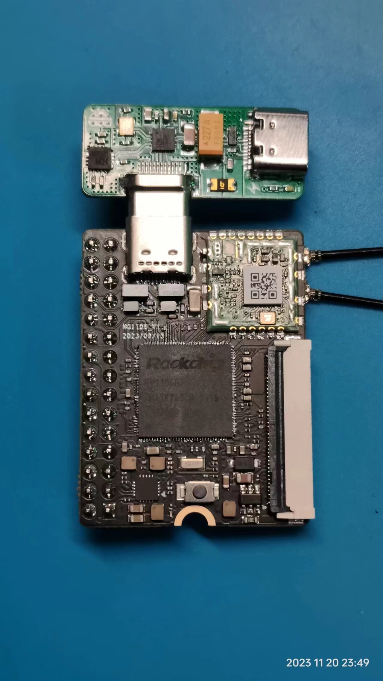
actual effect are included.)
PDF_SoloLinker-A USB Adapter Board.zip
Altium_SoloLinker-A USB Adapter Board.zip
PADS_SoloLinker-A USB Adapter Board.zip
BOM_SoloLinker-A USB Adapter Board.xlsx
97098
Matrix light panel
Matrix light panel
Matrix light panel
pen.mp4
PDF_Matrix Light Board.zip
Altium_Matrix Light Board.zip
PADS_Matrix Light Board.zip
BOM_Matrix Light Board.xlsx
97099
My first oscilloscope
My first oscilloscope project originated from the JLCIC EDA Instrumentation Training Camp jointly organized by JLCIC and Hardwood Classroom. It was an oscilloscope and a signal source analog front-end expansion board used with the STM32H750 core board.
This project is for circuit design reference only. You are welcome to perform secondary development and design according to your own needs.
The I/O allocation in this project is only applicable to the Hardwood Classroom H750 core board. Please refer to the schematic diagram for specific allocation details
. Signal conditioning circuit implementation:
Below, we will briefly introduce the analog input and output channels on the AFE03 board. We will then introduce the design and calculation methods in detail later.
INA, INB: The input terminals of the oscilloscope. The pocket instrument sends an analog signal and connects here. Here, a 1MΩ input impedance is achieved through a series resistor voltage divider, generating two signals for selection: one is a direct input, and the other is attenuated to 1/20.
gain: The selector switch selects either the direct signal or the signal attenuated to 1/20 to enter the first-stage non-inverting amplifier. The non-inverting amplifier performs two tasks: first, it amplifies the input signal at the non-inverting terminal by two times; second, it shifts the amplified signal by 1.65V, calculated as Vo = 1.65 + 2*Vi. Therefore, the overall gain of the corresponding circuit is 2 times or 1/10 times.

AnalogA and AnalogB: The analog signals, amplified and shifted by the inverting amplifier, are connected to the STM32H750 development board and enter the H750's ADC.
TrigerA and TrigerB: The square wave signals generated by AnalogA, AnalogB, and the DC reference level (generated by one of the H750's DACs) after passing through a comparator enter the STM32H750's timer for frequency measurement.
DAC_OUT1: The DC reference level is output through the STM32H750's internal DAC2
. The analog input channel
includes signal conditioning implemented with resistor dividers and operational amplifiers, and a square wave output implemented with a comparator.

The STM32H750's DAC1 output waveform ranges from 0-3.3V.
A second-order RC filter implements a low-pass filter function.

A resistor divider and buffer convert the 5V input to a low-impedance 2V output, which is then amplified by -5 times for shifting the output signal.
The output amplifier performs two functions: first, it amplifies the non-inverting input by 6 times; second, it shifts the amplified signal by -10V before outputting it. The calculation formula is Vo = -10 + 6 * Vi.
The voltage divider network is used to achieve better results when outputting small signals by utilizing analog circuit voltage division.
Analog input channel introduction:
This includes signal conditioning implemented with resistor voltage dividers and operational amplifiers, and square wave output implemented with comparators.
Attachment:
Demonstration video
; Test video link:
GG老刘's video submission - GG老刘's video sharing - Bilibili (bilibili.com)
202311210040.mp4
My First Oscilloscope.rar
PDF_My First Oscilloscope.zip
Altium_My First Oscilloscope.zip
PADS_My First Oscilloscope.zip
BOM_My First Oscilloscope.xlsx
97100
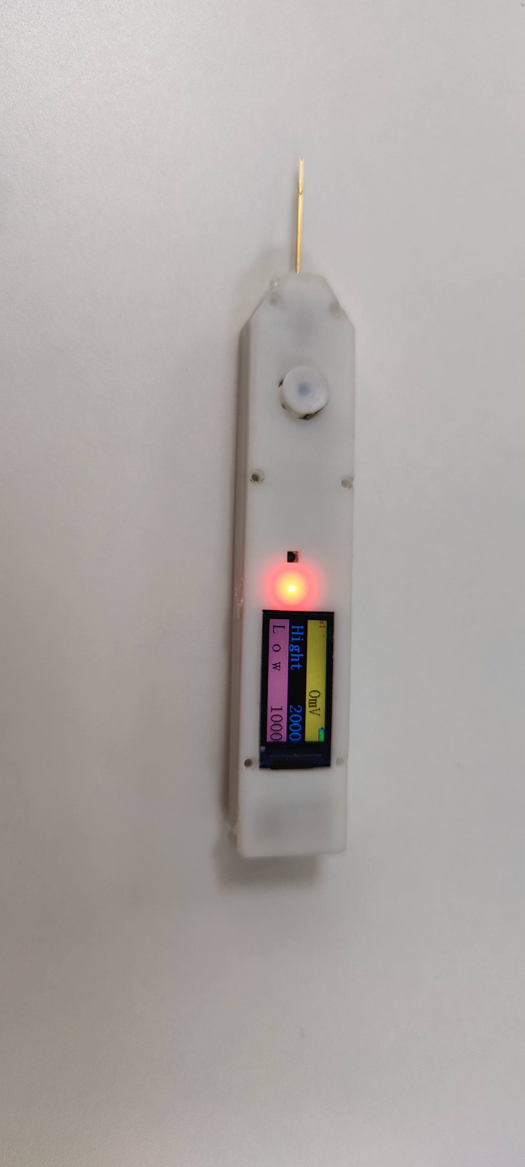
Multifunctional test pen
ZS-CW32 Multifunctional Testing Pen
This design utilizes the CW32F030 portable multi-functional test pen.
The test pen operates by simply tapping and holding a node on the circuit board to perform a test. (Note: "晶" refers to a transistor, a general term for all electronic circuits
.) The initial idea:
In daily hardware debugging, the most frequently used instrument is probably the multimeter. Although multimeters are called "all-purpose," most of the time, we only need to use them for voltage and continuity measurements.
As a powerful tool for debugging, multimeters sometimes have some drawbacks and limitations, such as: large size making them inconvenient to carry; inability to directly reflect logic levels requiring manual judgment; and different models of multimeters having different threshold resistances for continuity settings. The most troublesome issue is that the COM probe of a multimeter usually needs to be grounded, but the PCB may not have a direct-plug hole for easily fixing the probe tip, thus requiring manual assistance with the "black probe," affecting operational flexibility.
Therefore, in 2022 I designed a "logic level test pen" to quickly measure the commonly used 3.3V and 5V TTL levels. At that time, I decided to make an "upgraded version". Time flies and it is now 2023. My idea for this test pen has gradually improved in my mind. With the support of the "CW32 Ecosystem Community", I decided to turn this design into a physical product.
II. Initial Conception
My expectations for this test pen are as follows:
1. Voltage measurement + threshold judgment: The threshold level can be set to meet different logic level scenarios, while retaining the useful traffic light indicator function of the "simple logic level test pen";
2. Continuity measurement: The threshold resistance can be adjusted as needed (this is a feature only found in multimeters costing thousands of yuan, and I want to add it to my test pen);
3. Diode measurement: Measure the conduction voltage and light up a diode (Note! Not a transistor!!!);
4. PWM output: Convenient for providing a known quantity to test the system in some scenarios, and can also be used to test passive buzzers, etc.;
5. PWM input: Can measure frequency (and even perform simple decoding and display of serial port data, although this is not yet implemented due to current technical limitations);
6. DC output: Simulate a required DC level for testing (Thanks to Professor Li for proposing this requirement; I have found it very useful in use).
7. It can be connected to an expansion board for measurement (ideas for expansion modules are also welcome).
I also plan to open-source this project so more people can use it or modify and redesign it according to their needs. Therefore, I have paid extra attention to the following points:
1. Limiting the PCB length to within 10cm, so that everyone can "get" the PCB from JLCPCB for free.
2. All resistors and capacitors use 0603 packages, and LEDs use 0805 packages, making it easier to solder during your own construction (on the one hand, many people find 0402 components difficult to solder, and on the other hand, 0402 components generally do not have silkscreen markings, making it difficult to check if you solder incorrectly).
3. The project will strive to control costs (often, when making things for oneself, one might increase costs for precision or appearance; to facilitate replication of this project, a balance between functionality and cost will be sought).
III. Circuit Module Design:
When designing the test pen, I divided the overall design into five parts:
analog front-end
power supply and battery management
, microcontroller and peripheral
display screen , and
human-computer interaction (excluding other interactions on the display screen).
Based on a modular design approach, we can be more organized when drawing circuit diagrams and can roughly distinguish the layout according to modules during PCB layout, facilitating routing and other operations.
The circuit module design in this project is a common mixed-signal circuit design, applicable to many similar projects.
In the battery management, power supply, and microcontroller circuit modules, this project will strive to adopt standardized designs to improve the readability and replicability of the project's circuit diagrams.
IV. Circuit Design:
We will refine the design of each part according to the requirements to achieve the established goals.
Below, I will explain my design and design ideas in detail with the circuit diagram and PCB layout.
1. Power and Battery Management
1.1 Charge and Discharge Management
In the charging IC section, I chose the commonly used TP4057 as the main controller. The power input uses the most common Type-C interface. Although a 6-pin interface would be sufficient for this project, a 16-pin interface was chosen for scalability. The SBU1 and SBU2 pins of the Type-C interface were used for expansion board connections. D+ and D- were not used as expansion lines because the output signal of the device might cause the charger to misinterpret the signal, resulting in an incorrect voltage and potential danger. This needs to be considered in the design.
2. Microcontroller and Peripherals
2.1 The CW32 microcontroller core system
is a standard microcontroller core system configuration. Since this project does not require a high-precision clock and low-speed crystal oscillator for long-term timing, this part of the circuitry is omitted (it is drawn here, but set not to be transferred to the PCB or imported into the BOM, mainly so that it can be directly copied and used in other projects, primarily for CV engineers).
This project does not use a bootloader for programming, so the BOOT pin is directly pulled low (the standard drawing method can be found in the commented-out section; due to limited PCB space in this project, it is directly grounded). The SWD interface is PA13 and PA14, which are brought out using 1.0mm pitch headers in this project; however, in actual... No soldering of header pins is required during use; simply use a probe (an adapter board for probes is included in the project) to press against the interface to perform downloading. The header pinouts include SWD, RST, and MCUVCC, facilitating debugging. (The reset button on the PCB cannot be SMT soldered because the surface mount pads and header pin through-hole pads are reused, and reflow soldering will cause solder leakage, resulting in cold solder joints or even short circuits! The reset button is designed to be soldered after programming is complete, ensuring no further programming is needed. It can both block the header pin holes (yes, I have OCD) and function as a reset button (seems obvious). Even without soldering, a reset operation can be performed by shorting the RST and GND holes using tweezers or other metal objects.)
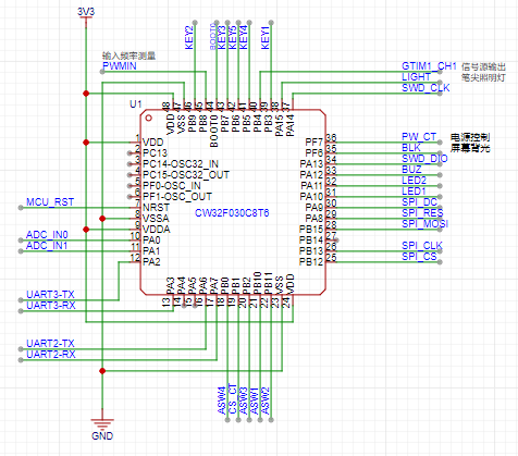
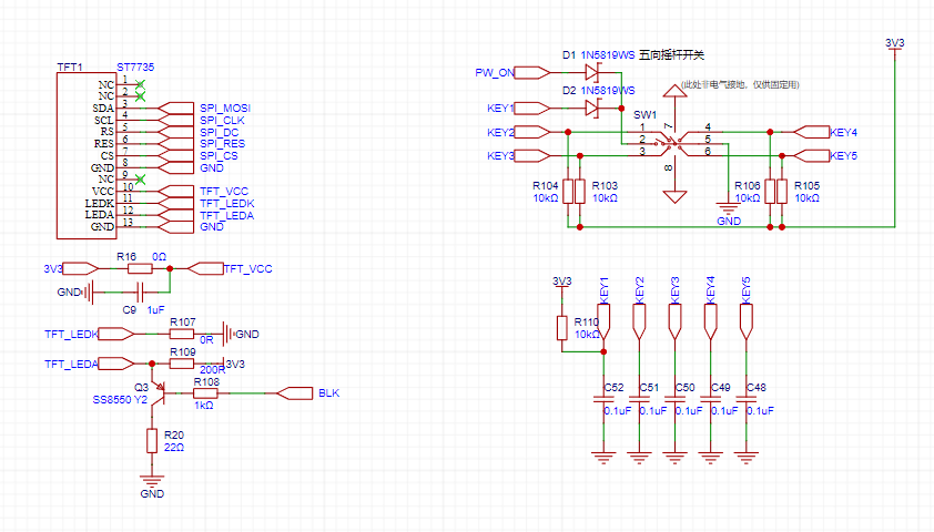
2.2 User Operation Input
The user operation section of this project uses a five-way joystick switch, which can be understood as equivalent to five ordinary button switches. Programming it is also done as ordinary buttons.
The functions corresponding to the joystick switch in different directions will be explained in the program section and will not be repeated here.

2.3 Display Screen
This project uses a 0.96-inch TFT display screen with a resolution of 80*160. It uses an ST7735 display driver chip and is connected to the PCB via FPC soldering, communicating through an SPI interface.

2.4 Other Human-Machine Interactions
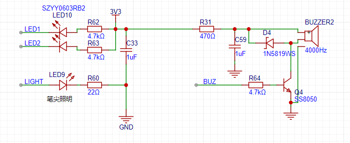
As shown in the figure above, the multi-functional test pen has two LEDs, one red and one green, for level indication. Green indicates a low level, and red indicates a high level (pay attention to the LED color during soldering). Both LEDs are connected to the MCU in current-sinking mode (Note: the LEDs and the display screen work simultaneously; the LEDs act as quick indicator lights, allowing users to easily determine the current status using peripheral vision).
A passive buzzer is used for additional indication (such as continuity testing) to enhance user experience. It's important to note that a passive buzzer is used here; an active buzzer cannot be used (given its small size, conventional active buzzers are not available).
Also note that a 200Ω resistor is connected in series in the buzzer's power supply to limit the current. If you find the buzzer's tone too soft or too loud in actual use, you can replace this resistor, but the resistance value should not be too small, otherwise excessive current will pull down the system voltage, causing malfunctions!
There is also a side-mounted LED as a pen tip light, convenient for testing in relatively dim environments such as inside the casing. The current-limiting resistor can be replaced to adjust the brightness to your needs.
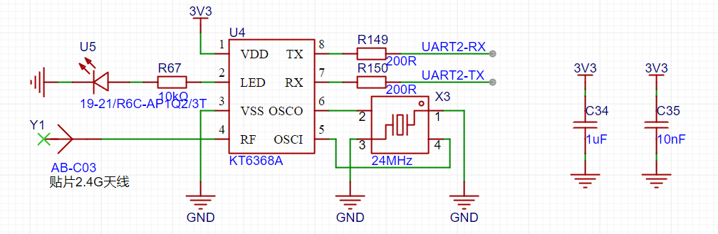
2.5 Bluetooth BLE
To facilitate connection between the pen and a computer or mobile phone, I chose to use Bluetooth BLE technology for wireless data transmission.
The main reasons for not using the more common CH340 serial-to-USB direct connection are as follows:
① The data cable has a certain weight and rigidity, and dragging the data cable during operation is less flexible than wireless operation;
② It is not recommended to use the device while the data cable is plugged in, as this will cause the floating ground of the test probe to become grounded, which may cause a short circuit during testing (the specific reasons will be analyzed in the analog circuit section);
③ The most important point: safety! If a high voltage is input to the test probe due to operational error, and the microcontroller burns out due to the failure of the protection circuit, this high voltage is very likely to be directly input to the mobile phone or computer along the data cable, causing serious damage!
3.1 Basic Design of Analog Front-End
Although this project is not to build a 10G oscilloscope (and I cannot build one at present), the design concept of analog front-end is similar, namely: what kind of signal will I collect, and what kind of signal will my device collect? If this is difficult to understand, let me give an analogy: I can hear English, but I only understand Chinese, so: I need a translator, and this translator is the "analog front-end" we need.
Let's return to the test pen project. My design goal for the system is as follows: it should be able to acquire signals from 0 to +15V and output signals from 0 to +5V. Okay, that's the most basic goal I need to achieve, isn't it simple?
However, this project has a special case: I want to complete all input and output functions on a single probe (I'm clearly a demanding client), which requires switching between input, output, and other states. At this point, some clever colleagues will immediately think of relays. Yes, relays are indeed very useful in this scenario, but they bring another problem: size. As this project is a portable test pen, I naturally don't want to make the device too big (it's inconvenient to use if it's too big). Relays are not suitable in this situation, so we need to introduce another switch, which is an analog switch.
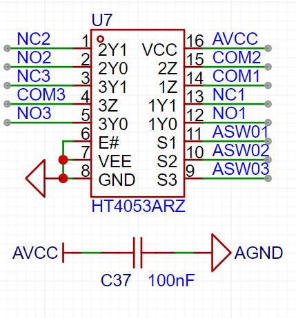
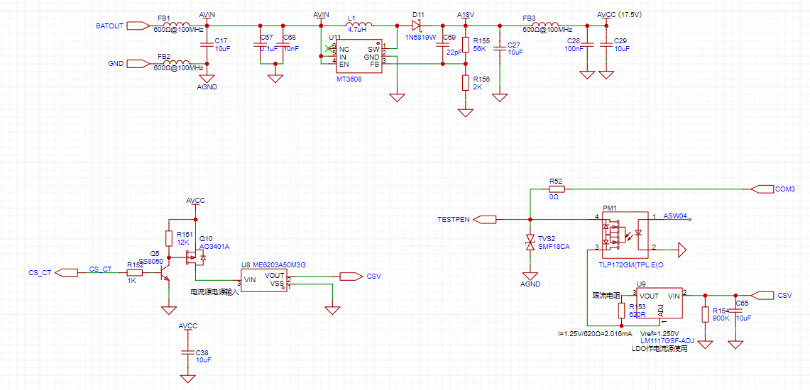
3.2 Analog Circuit Power Supply
Based on the HT4053A we selected, its maximum operating voltage is 18V. To allow for some margin, I designed the system voltage at 17.5V. Since the front-end voltage is directly powered by the battery, with a voltage of approximately 4.2V~3.5V, we need a boost circuit to power the analog front-end.
For chip selection, I chose the commonly used MT3608 chip. Its 2A output current is sufficient, and its relatively high switching frequency of 1.2MHz also helps with subsequent filtering. The boost inductor is a 4.7μH inductor in a mini SMD252010P package (2.5*2.0*1.0mm), which helps save PCB area (and is also more aesthetically pleasing). Although small in size, it has a rated current of 1.6A and a saturation current of 2A, which is sufficient for the system. Regarding the configuration of voltage divider resistors, although it may seem arbitrary, there are certain considerations. An inappropriate configuration will affect the power supply's output voltage ripple and load regulation performance. However, due to space limitations, this will not be elaborated upon here; interested students can consult relevant materials for further study.
It is important to note that this project does not use dual power supplies; that is, there is only a positive power supply and no negative power supply. Therefore, the test probe can only input/output positive voltage signals. If a negative signal needs to be input, the subsequent circuitry will also require some modifications. For size considerations, this project ultimately decided to use a single power supply solution.

3.3 Signal Input

/Output Circuit V. Hardware Soldering and Assembly
Hardware assembly involves many sequences. Mastering good soldering and debugging habits will help you save time and quickly locate problems. It also facilitates recording complete and detailed test reports, making it easier for software engineers to conduct independent testing and later hardware/software integration work (and also preventing software engineers from blaming hardware problems).
5.1 PCB Soldering
There is a specific order to PCB soldering. It's not that you can just solder everything at once. If you solder everything at once, it will be more difficult to pinpoint the problem if something goes wrong. Also, if the problem is with the power supply, it could damage a large part of the circuit. Below, I will introduce the recommended soldering and testing sequence for this project:
① Solder the Type-C interface and charge/discharge management circuit. Solder the battery to test the charge/discharge management circuit, and remove the battery after completion.
② Solder the power-on/off circuit and the five-way switch. Press the long button to test if the power supply outputs normally.
③ Solder the analog power supply and test if it is normal. If possible, test the output ripple.
(★Remember to solder the power supply first and complete the test before soldering the subsequent circuits to prevent power supply problems from affecting the entire circuit.)
④ Solder the analog switch and the analog switch control signal level conversion circuit. Manually apply a signal to test the level conversion.
⑤ Solder all analog front-end circuits and apply an analog signal to test the AIN test point voltage
. ⑥ Solder the microcontroller and red/green indicator lights. Then, you can burn the program and observe if the power-on is normal.
⑦ Solder other peripherals, pen tip, and tail plug (the soldering method can be found in the "Hardware Assembly Instructions" section).
⑧ Solder the display screen.
It is recommended to follow the above order for step-by-step soldering and testing. Even if you encounter component failures or other problems, you can quickly locate the problem.
Of course, if you don't want it to be that complicated, here's a summary of the soldering order: power supply (AVC test points), analog front-end (AIN test points), microcontroller and peripherals, and if you're used to using a hot air gun like me, you should use a soldering iron last to solder components that are easily damaged by the hot air gun: buzzers, displays, etc.

test_pen-master.zip
PDF_Multifunctional Test Pen.zip
Altium Multi-functional Test Pen.zip
PADS_Multifunctional Test Pen.zip
BOM_Multifunctional Testing Pen.xlsx
97101
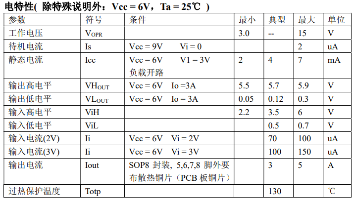
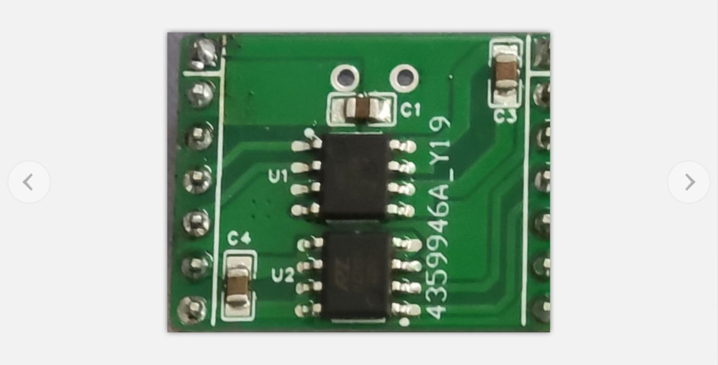
RZ7889
A dual H-bridge DC motor drive designed using the RZ7889. Verified.
Working Principle: The RZ7889 is a single H-bridge DC motor driver. This project uses two of these chips to implement a dual-channel motor drive.
Function: This module receives pulse signals from the I/O pins and controls the motor's direction and speed based on these signals.
The module's size and pin definitions are completely identical to the A4950 module, making it a direct replacement, and the chip is cheaper.
Operating Conditions: (See attached datasheet for details) Voltage 3-15V, Current 3-5A;
Physical Image:
RZ7889.pdf
PDF_RZ7889.zip
Altium_RZ7889.zip
PADS_RZ7889.zip
BOM_RZ7889 (A4950 Alternative).xlsx
97102
LCSC - Oscilloscope (To be completed)
Note that the specific information in the BOM (Bill of Materials) should be referred to the annotations in the schematic diagram!
The hardware schematic diagram shows the annotated circuit details, and
the software is developed using the standard library.


This project is a dual-channel oscilloscope based on the STM32F103C8T6. Due to the author's limited capabilities and unwillingness to directly use readily available "ready-to-use" code, the project completion period may be long, but the author will do their best.
The STM32F103C8T6 has a maximum clock speed of 72MHz and includes: 64K*8bit Flash, 20K*8bit SRAM, two 12-bit ADCs (12 channels total), one advanced timer TIM1, and three general-purpose timers TIM2, 3, and 4, etc.
An additional purchased module is a 1.8-inch 128*180 TFT screen.
The hardware project files contain the self-made board and examples provided by Hardwood Classroom. Hardware modifications include replacing all operational amplifiers with LMV321-TR (note the difference from "LMV321"; their power supply voltage ranges are different, and only the LMV321-TR is suitable for the ±12V power supply application in this project).
The software is developed using the standard library.
Currently implemented functions
: 1. Display the frequency of the measured signal;
2. Display a fixed background on the screen (hardware SPI1, to be ported or board pins modified);
3. Button control relay to select the magnification and display the corresponding magnification on the screen, initially defaulting to X10 magnification;
Short-term plans:
1. Port the screen from SPI1 to SPI2;
2. Implement DMA transfer to refresh a specified screen area;
3. Implement peak-to-peak and average value measurement;
4. Draw waveforms (data stored in an array and then displayed as dots?);
5. Modify the unit length of the encoder's horizontal and vertical axes (one encoder controls one channel, by detecting "press," the corresponding modification amount flashes to select whether to modify ScaleX or ScaleY, while the screen updates the unit length information);
6. Self-built Chinese character library, with button selection for Chinese or English version;
7. Add an acrylic panel shell;
Further vision (to be done depending on time and capabilities):
1. Reselect the main control chip, with sufficient resources and cost reduction as much as possible
; 2. Store waveform information on an SD card (c8t6 does not have an SD card interface);
3. Run the system? I haven't looked into it in detail yet (it seems the oscilloscopes in the lab all run operating systems?) (FreeRTOS and UCOS);
4. Low-power mode when not in use?
WeChat_20231120141034.mp4
LCSC - Oscilloscope.doc
Ming-LCSC Oscilloscope Code - No Portable Screen Flying Wire Version.zip
PDF_LCSC - Oscilloscope (To be completed).zip
Altium_LCSC-Oscilloscope (To be completed).zip
PADS_LCSC-Oscilloscope (To be completed).zip
BOM_LCSC-Oscilloscope (To be completed).xlsx
97103
electronic


 京公网安备 11010802033920号

 NACS101M505x5.5


