CW32 Multifunctional Test Pen
- Portable Multifunctional Test Pen Design Based on CW32F030
"Point
" refers to the pen's operation method; simply tap a node on the circuit board to perform a test. "Crystal" refers to a transistor, generally referring to all electronic circuits.
1. Power and Battery Management
1.1 Charge and Discharge Management
In the charging IC section, I chose the commonly used TP4057 as the main controller. The power input uses the most common Type-C interface. Although a 6-pin interface would be sufficient in this project, considering the project's expandability, a 16-pin interface was chosen. The SBU1 and SBU2 pins of the Type-C interface were used for expansion board connections. The reason for not using D+ and D- as expansion lines is that the device's output signal may cause the charger to misinterpret, resulting in an incorrect voltage and causing danger. This needs to be considered in the design.

2.1 CW32 Microcontroller Core System
The standard microcontroller core system configuration is omitted here because this project does not require a high-precision clock and low-speed crystal oscillator for long-term timing (it is drawn here, but set not to be transferred to PCB or imported into BOM, mainly so that it can be directly copied and used in other projects, primarily for CV engineers).

2.2 User Operation Input
The user operation part of this project uses a five-way joystick switch, which can be understood as equivalent to five ordinary button switches. Programming it is also done as ordinary buttons. "

Point Crystal"
: Point refers to the operation mode of the test pen; lightly touching a node on the circuit board performs a test; Crystal refers to transistor, generally referring to all electronic circuits.
1. Power and Battery Management
1.1 For charging and discharging management,
I chose the commonly used TP4057 as the main controller in the charging IC section. The power input uses the most common Type-C interface. Although a 6-pin interface would be sufficient for this project, a 16-pin interface was chosen for scalability. The SBU1 and SBU2 pins from the Type-C interface were used for expansion board connections. D+ and D- were not used for expansion circuitry because the device's output signal might cause the charger to misinterpret the signal, resulting in an incorrect voltage and potential danger. This needs to be considered in the design.
2.1 CW32 Microcontroller Core System:
Standard microcontroller core system configuration. Since this project does not require a high-precision clock and low-speed crystal oscillator for long-term timing, this part of the circuit is omitted (it is drawn here, but set not to be transferred to the PCB or imported into the BOM, mainly so that it can be directly copied and used in other projects, primarily for a CV engineer).
2.2 For convenient connection between the test
pen and a computer or mobile phone, I chose to use Bluetooth BLE technology for wireless data transmission.

"Point-to-Point Pen": "Point
" refers to the operation method of the test pen; lightly touching a node on the circuit board initiates the test. "Crystal" refers to a transistor, generally referring to all electronic circuits.
1. Power and Battery Management
1.1 Charge and Discharge Management
In the charging IC section, I chose the commonly used TP4057 as the main controller. The power input uses the most common Type-C interface. Although a 6-pin interface would be sufficient for this project, considering the project's expandability, a 16-pin interface was chosen. The SBU1 and SBU2 pins from the Type-C interface were used for expansion board connections. D+ and D- were not used as expansion lines because the device's output signal might cause the charger to misinterpret the signal, resulting in an incorrect voltage and potential danger. This needs to be considered in the design.
2.1 The CW32 microcontroller core system
is a standard microcontroller core system configuration. Since this project does not require a high-precision clock and low-speed crystal oscillator for long-term timing, this part of the circuitry is omitted (it is drawn here, but set not to be transferred to the PCB or imported into the BOM, mainly so that it can be directly copied and used in other projects, primarily for a CV engineer).
2.2 User Operation Input
The user operation part of this project uses a five-way joystick switch, which can be understood as equivalent to five ordinary button switches. Programming it is also done as ordinary buttons.
"Point Crystal": The operation method of the point crystal pen
; "Point" refers to the operation mode of the test pen, lightly touching a node on the circuit board to perform a test; "Crystal" refers to a transistor, generally referring to all electronic circuits
. 1. Power and Battery Management
1.1 For charging and discharging management,
I chose the commonly used TP4057 as the main controller in the charging IC section. The power input uses the most common Type-C interface. Although a 6-pin interface would be sufficient for this project, a 16-pin interface was chosen for scalability. The SBU1 and SBU2 pins from the Type-C interface were used for expansion board connections. D+ and D- were not used for expansion circuitry because the device's output signal might cause the charger to misinterpret the signal, resulting in an incorrect voltage and potential danger. This needs to be considered in the design.
2.1 CW32 Microcontroller Core System:
Standard microcontroller core system configuration. Since this project does not require a high-precision clock and low-speed crystal oscillator for long-term timing, this part of the circuit is omitted (it is drawn here, but set not to be transferred to the PCB or imported into the BOM, mainly so that it can be directly copied and used in other projects, primarily for a CV engineer).
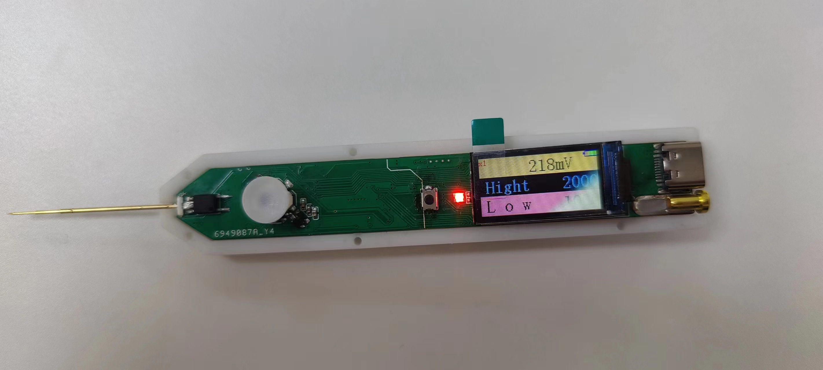
2.3 Analog Front-End and Input/Output


Physical Verification:


 京公网安备 11010802033920号

 177-710-2-51CS4J7-24PCN


