0. Foreword
As a mechanical engineering student, I often need to use power supplies when debugging electromechanical equipment during projects. However, linear power supplies and switching power supplies have limitations in different aspects and are difficult to adapt to diverse requirements. Therefore, designing a compact digital power supply has been a long-planned project, but from my sophomore to senior year, I was unable to find the time to implement it due to various reasons. This training camp really pushed me and filled the long-standing pit I had dug.
This project is the first time I have independently completed all related work. Previously, I was mainly responsible for the mechanical and hardware parts in teams and projects. It is foreseeable that there are still many areas for improvement in the project, especially in the software part. Welcome to offer relevant suggestions. This project will be continuously modified and updated as a long-term project (a new project will be created if there is a major iteration).
0.1 Actual Product Images

Figure 1 Front of the Power Supply
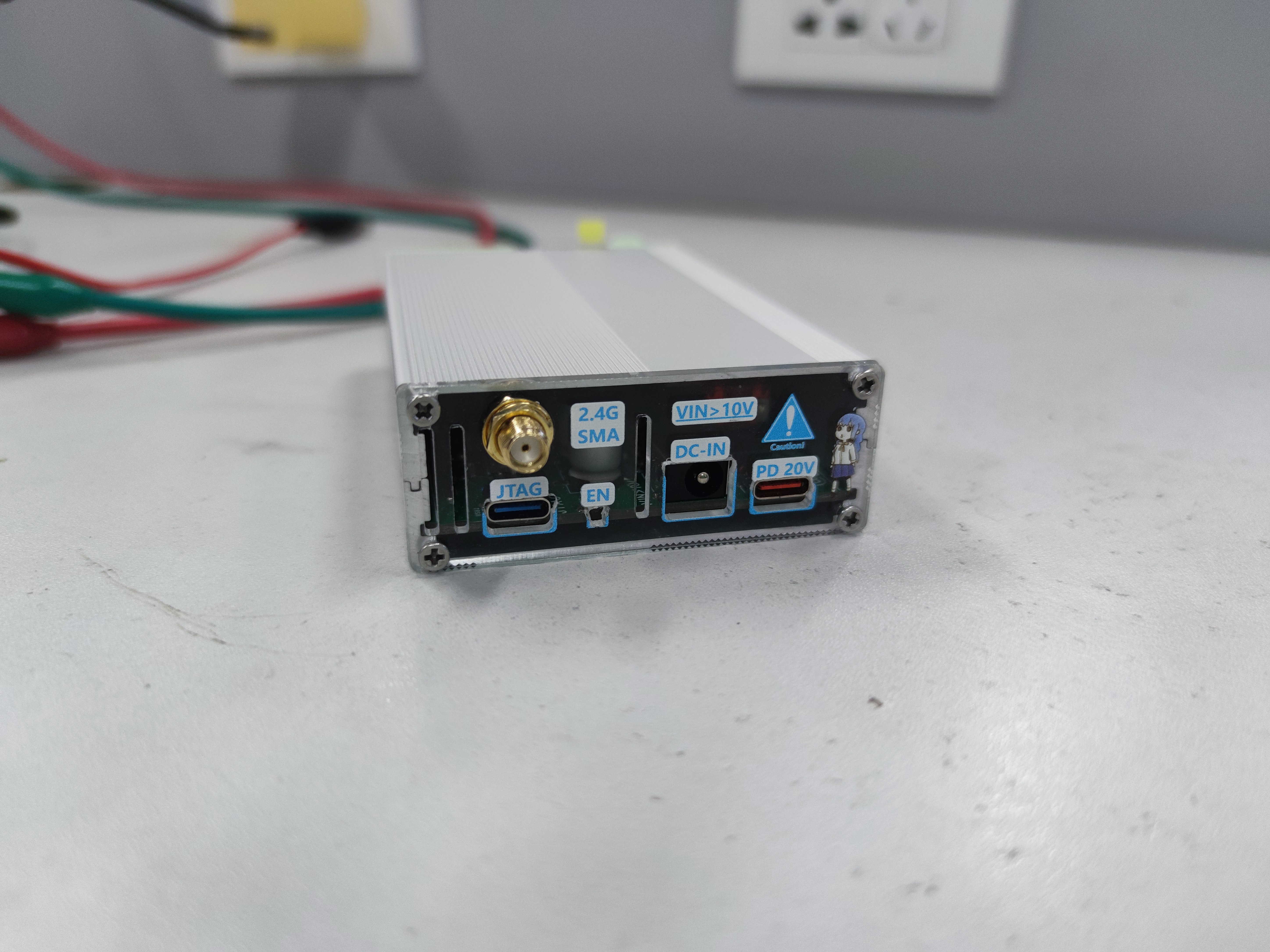
Figure 2 Back of the Power Supply
* Small Panel · Masterfully Made - Purely Handcrafted (Some idiot forgot to calculate the board thickness offset of 1.6mm) *

Figure 3 Exploded View of the Power Supply (weird)
Abstract
Sorry, I had a medical condition and there is no abstract.
I. Basic Characteristics
1.1 Electrical Characteristics
Input Voltage: 10V ≤ Uin ≤ 24V (10V - SC8701 PG requirement)
Output Voltage: 3V ≤ Uout ≤ 25V (Software limitation, 25V - INA219 VBUS requirement)
Output Current: Iout ≤ 5A (Engineering PCB design limitation)
Sampling LSB: 1LSB - 10mV (For voltage sampling)
1.2 Usage Characteristics
TFT information display and key encoder interaction
JTAG-serial port host computer interaction
Reserved Bluetooth and WIFI functions to be developed
1.3 Hardware Characteristics
DC-DC Topology: Buck-Boost
DC-DC Controller: SC8701QDER
MCU: ESP32-S3-WROOM-1U-N16R8 (High blood pressure during initial debugging, impulsively went for a full set of S3s)
Sampling & Output Amplifiers: LM358, LMV321, LM321 (Slightly overclocked but not a major issue)
Current Sampling: INA219 (Some issues, detailed below)
II. System Framework
2.1 Main System Framework

Figure 4 Main System Framework Diagram
2.2 Power Network Framework

Figure 5 Power Network Framework Diagram
2.3 Panel Interaction Logic (For Constant Voltage Output)

Figure 6 Panel Interaction Logic Diagram (For Constant Voltage Output)
2.4 Serial Port Interaction Logic (For Constant Voltage Output)
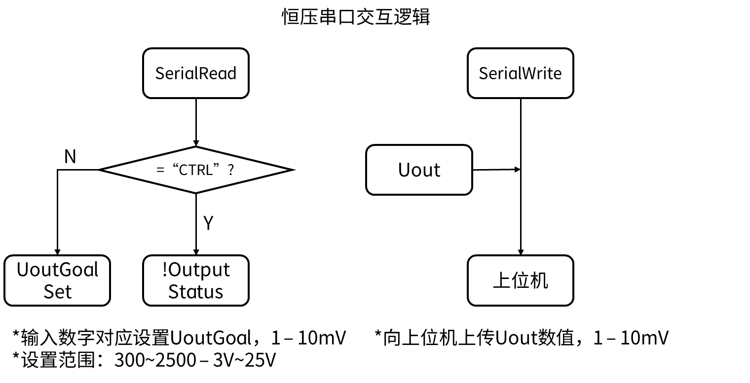
Figure 7 Serial Port Interaction Logic Diagram (For Constant Voltage Output)
III. Design Ideas
Controllable output meeting common voltage values (3.3V, 5V, 9V, 12V, 19V, 24V - therefore, 3.3V ≤ Uout ≤ 24V)
Relatively considerable output capability (designed for 100W)
Ability to use USB Type-C power supply (for portability)
... (I've considered many things, but this is all I can think of for now)
3.1 DC-DC Topology Design Ideas
Common portable digital power supplies on the market often use the Buck topology, which limits the output voltage to a maximum of the input voltage (e.g., a certain atom). Therefore, a topology with buck-boost functionality is needed.
I considered two topologies: SEPIC and Buck-Boost.
I won't go into the comparison of the advantages and disadvantages of the two topologies, as there are many resources online. The main reason for choosing Buck-Boost instead of SEPIC is my psychological aversion to SEPIC; I had previously tried to verify it but failed.
Before starting this project, I designed a Buck-Boost solution verification version based on the SC8701 (which will be open-sourced later) by referring to some open-source projects. After successful verification, I gained confidence and began working on the hardware design of this project.
Regarding controller selection, the main considerations were cost and availability of resources.
Cost: Well... Limited
resources: Reference materials, open-source solutions, verification versions, etc., can provide reference and reduce the resistance encountered in design and development.
After comparison and consideration, I chose the SC8701.
3.2 Framework and MCU Selection Approach
This project is based on the Arduino framework for developing the ESP32-S3.
Why choose Arduino and ESP32-S3?
Mainly because I'm a beginner. I mainly worked on hardware before, and my software experience is relatively weak, so I chose the easier one.
3.3 Component Selection
Due to years of hardware design experience (through freeloading), I have accumulated a lot of components, so the selection is mainly based on the components I have on hand.
If you have replicas available, you can replace them as appropriate.
3.4 Hardware Design Approach
I mainly divide the hardware design into four parts: control, power supply, interface, and interaction.
Control: The hardware design is based on the ESP32-S3-WROOM-1U-N16R8, including the MCU module, MCU peripheral circuits, voltage & current sampling, and output control.
Power Supply: The main design is based on the SC8701 Buck-Boost topology, which realizes DC-DC conversion of the main input and output; power supply guarantees -10V, 5V, and 3.3V, using a Buck DC-DC converter and an LDO.
Interfaces: Power input (DC, Type-C); Debugging (JTAG Type-C, UART header); Connection between main board and interaction board (using PCIe x1, solder finger connection).
Interaction: Display (TFT ST7735 0.85); Buttons (tactile switch); Encoder (EC11)
and modular design based on the above division.
Relatively simple, here we will focus on the design of voltage sampling circuit and output control circuit.
3.4.1 Voltage Sampling
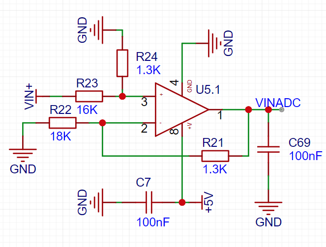
Circuit Figure 8 Voltage Sampling Circuit Schematic
Here I use a combination of on-chip ADC and operational amplifier circuit, where the sampling operational amplifier circuit focuses on range scaling transformation.
The ESP32-S3 has two 12-bit ADCs with a total of 10 channels, a reference voltage of 3.3V, and a sampling value of 0~4095.
To make the sampled value more intuitive and establish a clearer relationship between the sampled value and the actual voltage, scaling transformation is required. As follows:

Considering DC-DC power output, control accuracy, and feasibility, I transformed the scale to 0~4095 - 0~40.95V, i.e., 10mV per LSB.
To reduce costs, I used E24 series resistors to configure the op-amp amplification factor and considered the impedance matching factor at both ends of the op-amp input for the solution.
I used a genetic algorithm for multi-objective optimization, constructing a fitness function with the absolute value of the amplification factor error as the primary optimization objective and the absolute value of the impedance deviation as the secondary optimization objective. The results are as follows:

Figure 9 Voltage sampling circuit configuration resistor optimization solution
R1 = 18K; R2 = 1.3K; R3 = 16K; R4 = 1.3K
Amplification factor deviation: 7.0199e-05
Input matching deviation: 0.0195
This completes the parameter design of the voltage sampling circuit. (See attached program)
3.4.2 Output control

circuit Figure 10 Output control circuit schematic
I used a resistor network to control the output voltage, and the input voltage at the control terminal will be inversely proportional to the output voltage in a first-order linear relationship.

Figure 11 shows the resistor network control (@BV1oC4y1V7k1).
Originally, the plan was to use an on-chip DAC for output control. However! The ESP32-S3 does not have a DAC (ESP32 → ESP32-S3 reverse upgrade).
Therefore, a PWM output combined with a second-order low-pass filter was used to simulate a DAC for control.
The resistance values of each component of the feedback resistor network jointly determine the output voltage range.
As derived from the power supply range analysis and device limitations in Figure 3: 2V ≤ Uout ≤ 26V
. Similarly, a fitness function was constructed using the absolute value of the output voltage deviation, and a genetic algorithm was used for optimization. The results are as follows:
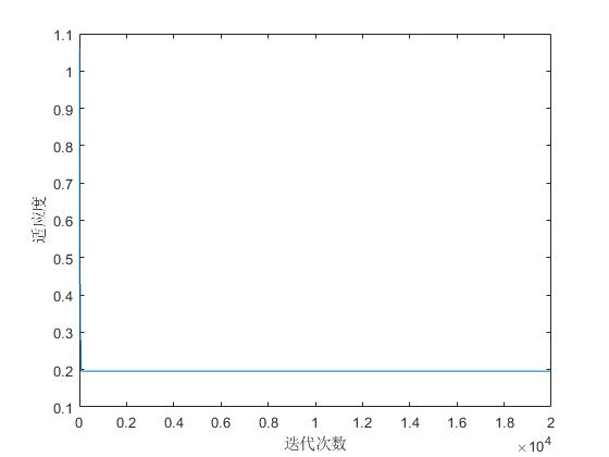
Figure 12 shows the optimized output resistor network configuration:
R1 = 13K; R2 = 1K; R3 = 1.8K;
Uout_max = 25.3911V
; Uout_min = 2.1667V
. This completes the parameter design of the output control circuit. (See attached program)
IV. ESP32-S3 Programming
The ESP32-S3 mainly needs to implement the following functions:
voltage and current sampling,
output voltage control,
output control,
local interaction, and
host computer interaction .
4.0 Development Environment
This project program is developed based on VSCode PlatformIO and the Arduino framework.

Figure 13 Development Environment
4.1 Voltage and Current Sampling Program
4.1.1 Voltage Sampling
Voltage sampling is relatively simple; just use the analogread() function to read the value of the corresponding ADC pin.
4.1.2 Current Sampling
Current sampling requires communication with the INA219 via the I2C bus. In Arduino, this requires calling the Wire.h library or other third-party libraries (well-encapsulated).
I tried three methods: using the Adafruit_INA219.h library, the INA226.h library, and directly reading from the Wire.h library. Unfortunately, the read values were not normal, suggesting that the INA219 might be damaged. Current sampling is not currently implemented.
4.2 Output Voltage Control
Output voltage control is relatively simple. The `analogwrite()` function is used to control a specified IO to emit a PWM wave, with a range of 0-255 (sufficient; the actual control scale is approximately 10mV, similar to the voltage corresponding to the LSB detection).
The set target output voltage `UoutGoal` is converted into a PWM control value according to the relationship in Figure 11, and the PWM wave duty cycle is controlled to achieve output voltage control.
4.3 Local Interaction
Local interaction includes button interaction, encoder interaction, and screen display.
4.3.1 Button Interaction
I used the `Onebutton.h` library to call button functions. This library can set events such as single click, double click, and long press.
4.3.2 Encoder Interaction
I used the `Encoder.h` library to read encoder values. By comparing the current value with the previous value, the left and right rotation of the encoder can be determined, and the corresponding values can be adjusted.
Note that I tried placing the function for reading the encoder position in a timer event, but the read information was very strange, almost only increasing and never decreasing. When I placed the function inside the void loop() main loop, the functionality and information reading were normal (reason unknown).
4.3.3 Screen Display:
The ST7735 screen is driven using the TFT_eSPI.h library.
4.4 Host Computer Interaction:
Serial communication with the host computer is now complete. This is divided into two parts: uploading data and receiving control.
Output voltage information is uploaded to the host computer using Serial.println(); instructions from the host computer are read using Serial.read(), and corresponding control or adjustments are made.
4.5 Timer Events
: Most tasks require timed completion. Examples include data acquisition, output control (PID control), serial port upload, and TFT refresh.
Two timers (1, 2) are used: Timer 1 for data acquisition, output control (PID control), and serial port upload; Timer 2 for TFT refresh.
4.6 Other:
In programming, decimal calculations are inevitably used, requiring the use of float to define variables.
However, when I define variables using float, the program restarts as soon as it reaches the point of using float variables. When the variable is defined using double, the function works normally (the reason is unknown).
V. Debugging
is here, the most stressful part is here.
Debugging is extremely frustrating, and this project almost made me turn from a fan of the ESP series to a hater.
5.1 Flash/PSRAM
To be honest, I am not very interested in this thing, and I don't know how much optimization and improvement it can bring.
But! It occupies IO extra!

Figure 14 PSRAM pin correspondence table [4]
As shown in Figure 13, the Flash/PSRAM driven by the eight-wire SPI will occupy GPIO33-37 extra.
In the design, I used some of these pins to drive ST7735 and enabled the PSRAM function.
At this time, the high blood pressure comes. Every time it starts, ST7735 SPI and PSRAM are fighting for GPIO. Whether it can start normally depends entirely on luck. One reset may cause it to fail.
I reread the datasheet and found the problem, which was solved by disabling the PSRAM function. (So, xdm, memorize the entire datasheet!)
The main issue was my lack of clarity regarding the ESP32-S3, so I hope everyone will learn from this and pay attention to the important details mentioned in the datasheet.
5.2 ADC Calibration
After completing the main function program, I started testing the output. At this time, I found that the output/input voltage was inconsistent with the values of the multimeter and ammeter.
Therefore, I compared the measured value with the output value and obtained the following results:
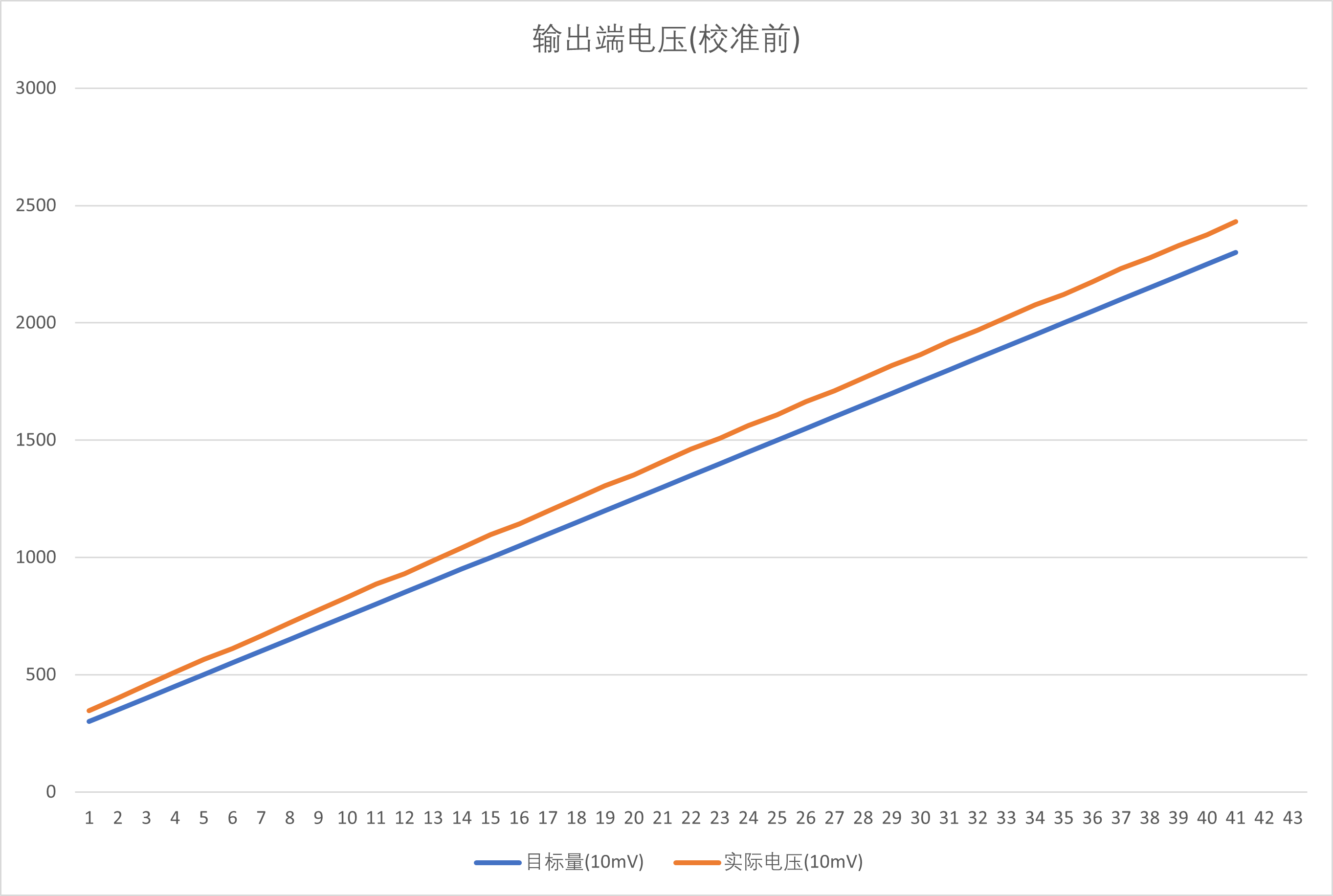
Figure 15 Output value-measured value comparison (before calibration)
As shown in the figure above, it can be seen that the slope and height of the two lines between the actual voltage measurement value and the output value are different, and there is a deviation in slope and intercept.
It is easy to see that the error value mainly follows a first-order linear distribution.
Therefore, I defined CorrectUout (slope calibration) and UoutOffest (intercept calibration) to calibrate the ADC.
I imported the measured values into Matlab and performed a first-order linear fit between the actual control quantity and the actual measured value. The results are as follows:
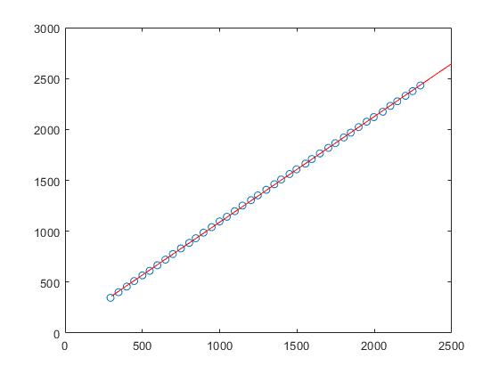
Figure 16 shows the linear fitting results:
CorrectUout = 1.0384,
UoutOffest = 50.8339.
These results are then used in the program to calibrate the ADC.

Figure 17 shows the comparison between the output value and the measured value (after calibration).
As shown in the figure above, the actual control value and the actual measured value are well consistent after calibration, with a small deviation, which may be caused by measurement error or control error.
It is speculated that the slope difference comes from the amplification error of the sampling operational amplifier circuit, possibly caused by resistance error, etc.;
the intercept error comes from the on-chip ADC's own reference drift (speculation).
The ADC calibration is now complete, and the calibration effect is good. (Program and documentation are attached.)
5.3 PID Parameter Tuning
The accuracy of the output voltage and power supply ripple are greatly affected by the MCU control; therefore, the suitability of the PID parameters will significantly affect the power output quality.
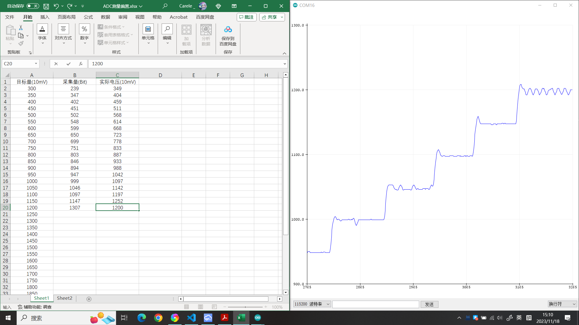
Figure 18 shows the PID parameter tuning and debugging.
Currently, there are still some problems with the PID parameter settings, such as static error, large overshoot, and oscillation.
Therefore, further parameter tuning is still needed.
VI. Performance Testing
6.1 Conversion Rate Test
To test the power supply performance, I used an electronic load.
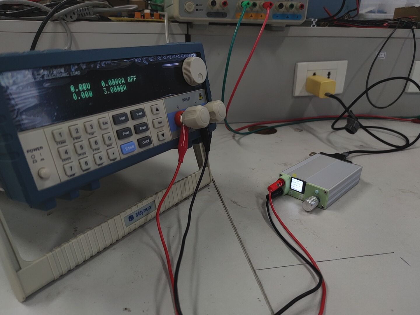
Figure 19 Performance Testing Environment
* Load borrowed from the teacher *
Input Conditions: Nubia GaN Gallium Nitride Single-Port 65W Charger @ 20V 3.25A max
Input Information: Juwei Safe Charging Multifunctional Tester (USB Current and Voltage Meter)
Output Information: Electronic Load
Test results are shown below:
Table 1 Test Results

As shown in the table above, the power supply has a low conversion rate under high current load conditions, presumably due to a large MOS/inductor internal resistance.
6.2 Ripple Test
The AC coupling mode of an oscilloscope was used for testing, and the following results were obtained:
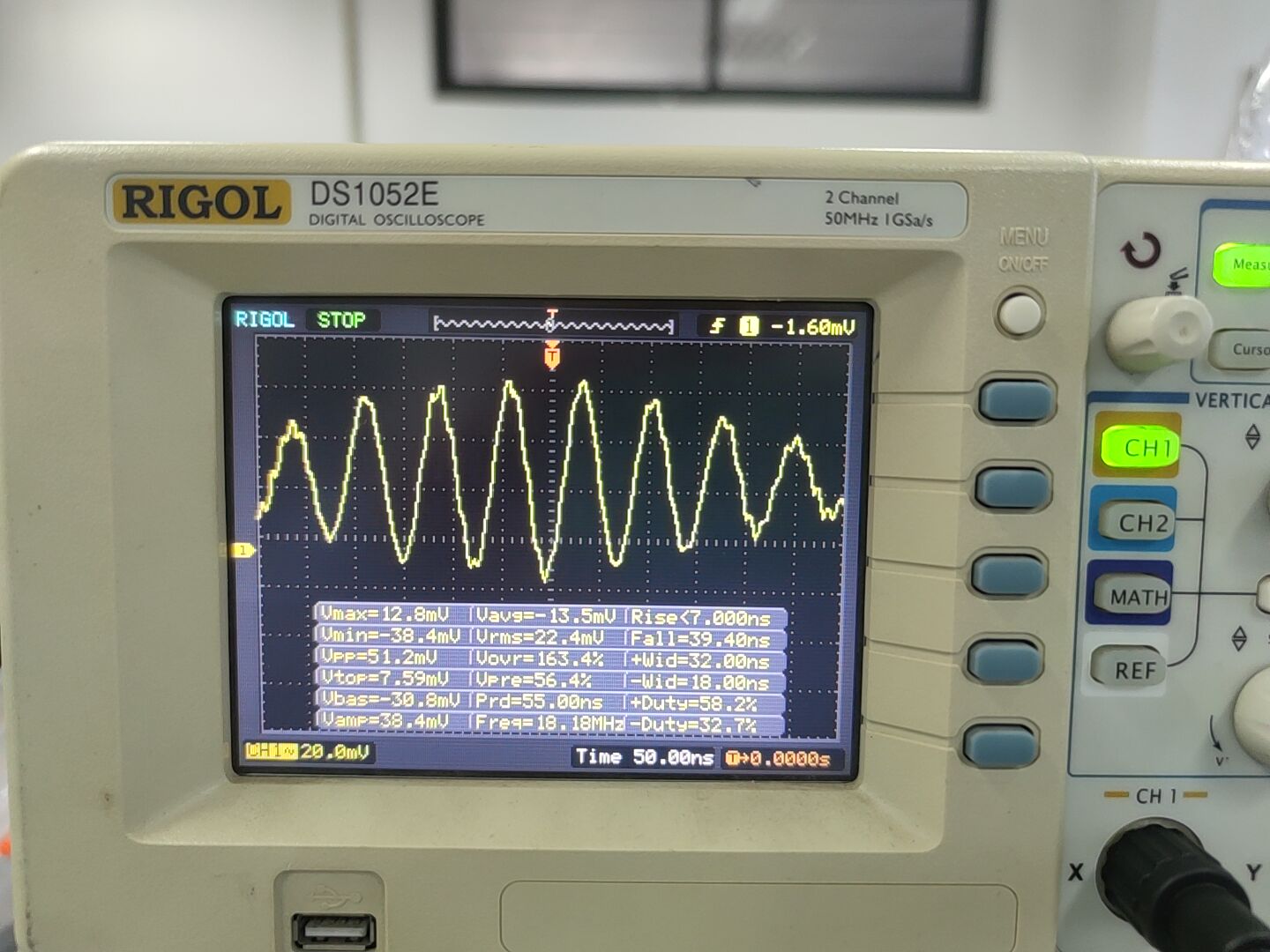
Figure 20 Ripple Test Results
Hmm, not bad? But something feels off.
*The above results are not entirely accurate and are for reference only.
VII. Power Supply Assembly
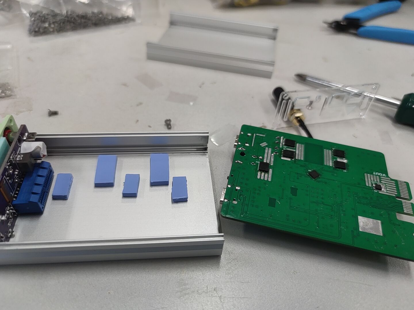
Diagram 21 Power Supply Assembly Diagram 1 (Use a 3mm thermal pad to conduct heat from MOS and chip to the casing)
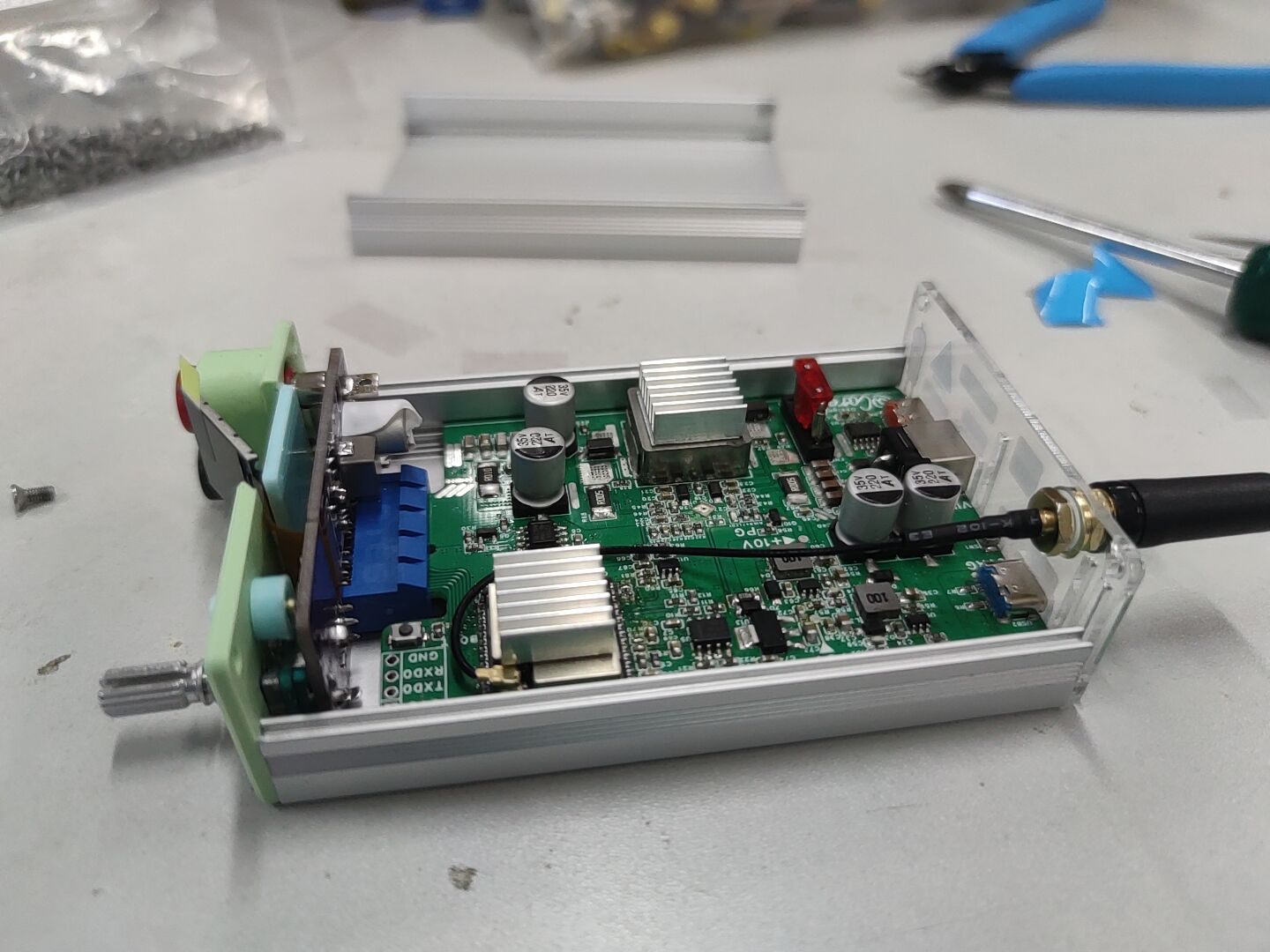
Figure 22 Power Supply Assembly Diagram 2 (Add a 14x14x5 heat sink to assist inductor and MCU module heat dissipation)
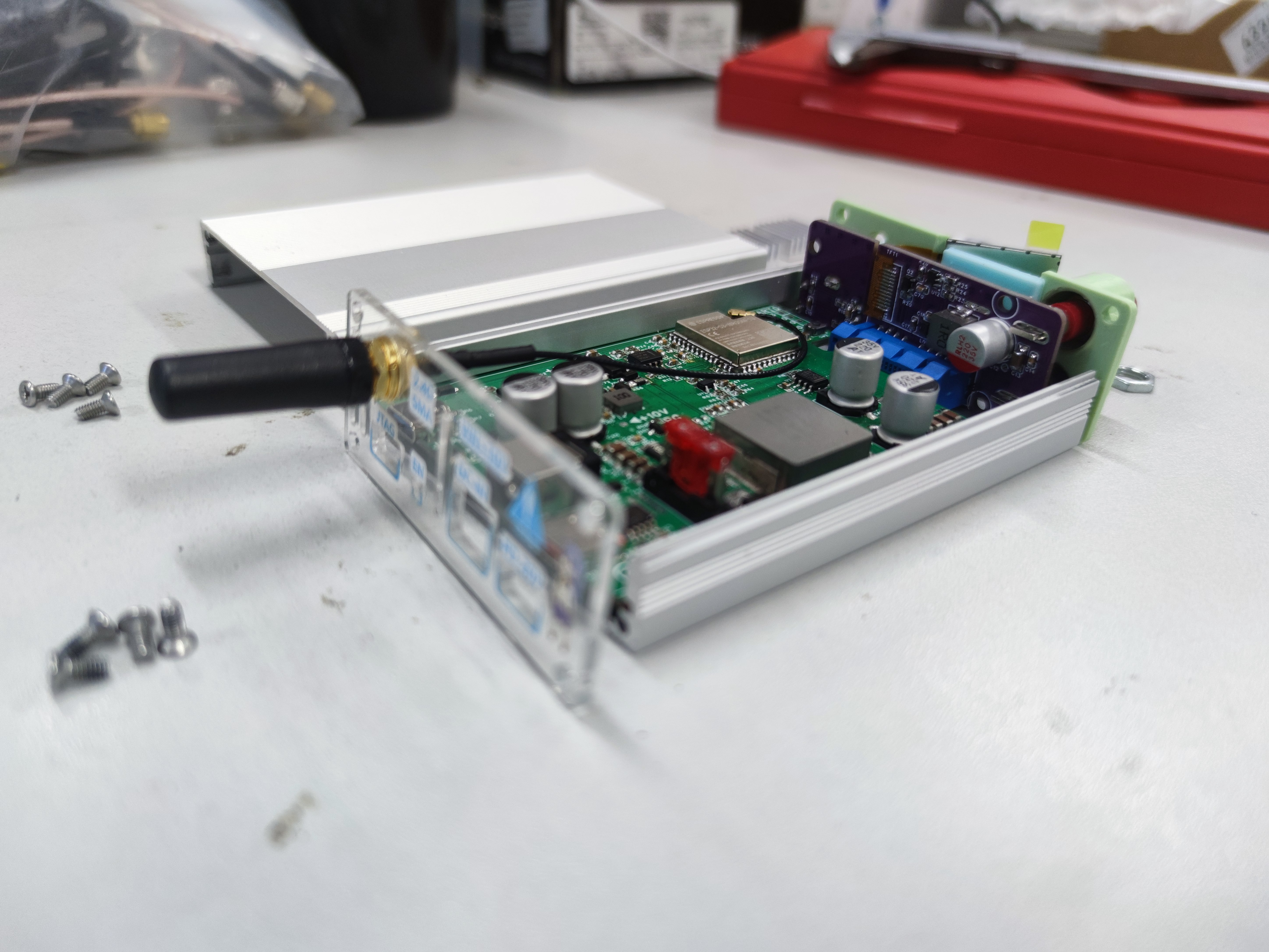
Figure 23 Power Supply Assembly Diagram 3 (Use M2.5x6 screws to fix the front and rear panels)
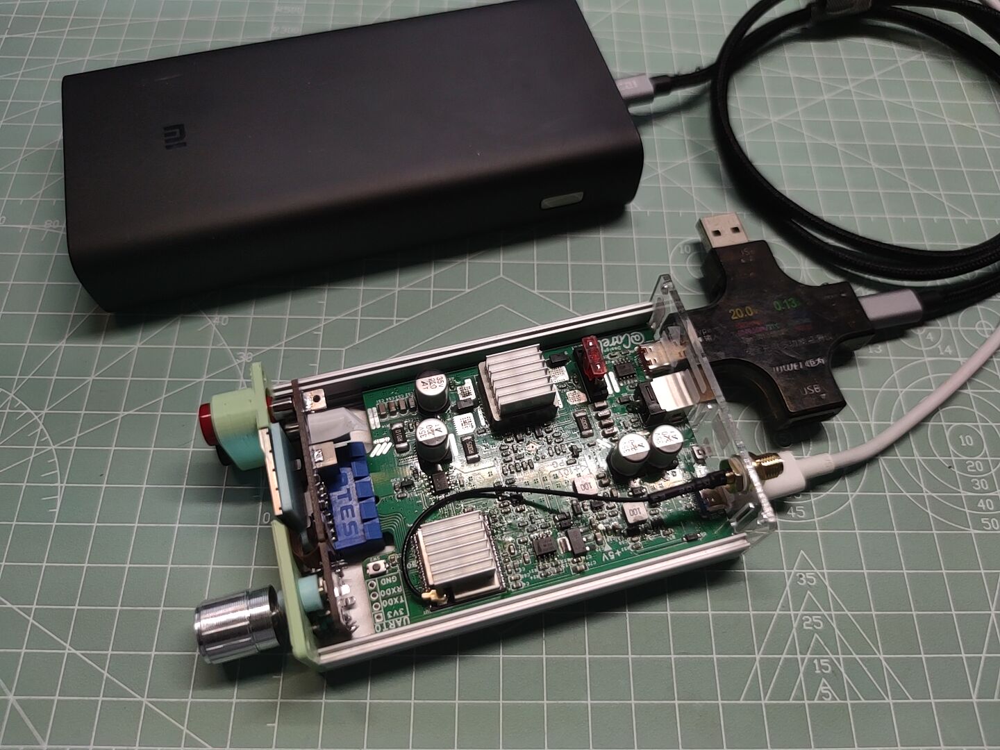
Figure 24 Power Supply Assembly Diagram 4
VIII. Power Supply Effect

Diagram Figure 25 Power Supply Effect Diagram 1 (Front Panel) Figure 26 Power Supply Effect Diagram

2 (Rear Panel - The hole position deviation of the panel in the project has been corrected)
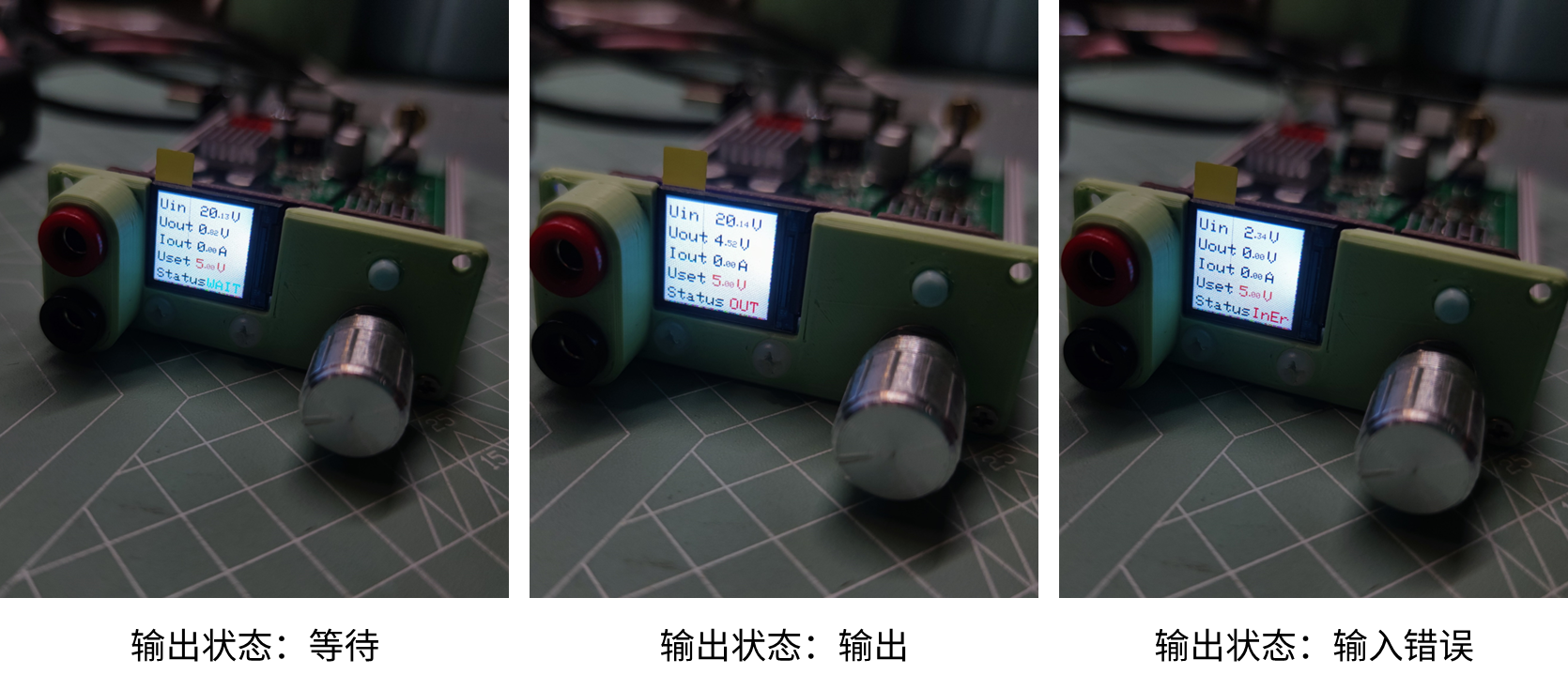
Figure 27 Power Supply Effect Diagram 2 (Output Status: Wait | Output | Input Error)
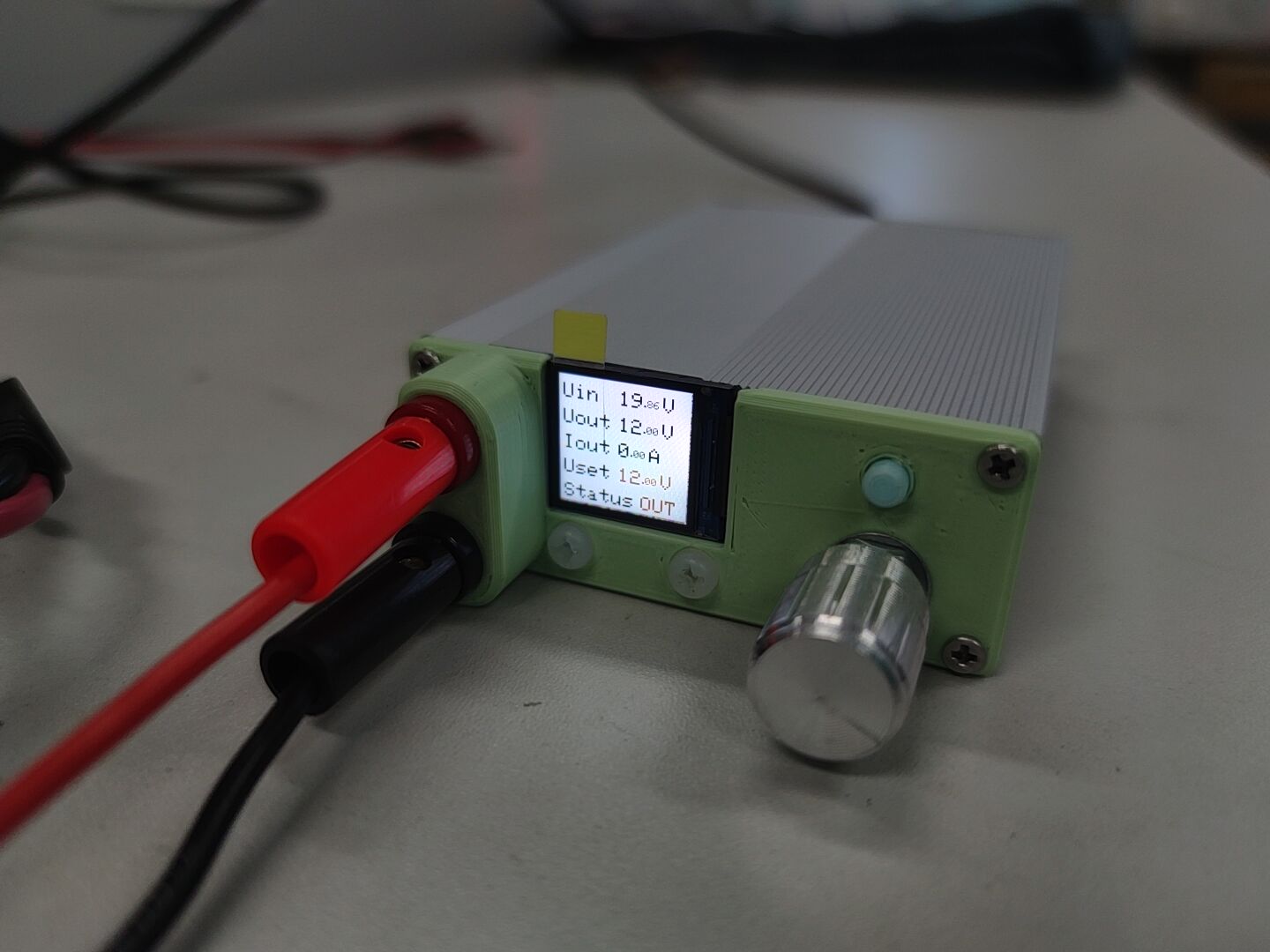
Figure 28 Power Supply Effect Diagram 4 (Use a 4mm banana plug to connect the output end)
References
SC8701
[1] Manual: SC8701 https://www.semiee.com/file/SouthChip/SouthChip-SC8701.pdf
[2] Open Source Project: SC8701 Buck-boost adjustable DC-DC verification https://oshwhub.com/8bit_in_1byte/sc8701-ke-diaodc-dc
[3] Open source project: 636 - SC8701 automatic buck-boost car charger https://oshwhub.com/LoveTombSeries/LoveTomb636
ESP32-S3-WROOM-1U-N16R8
[4] Manual: ESP32-S3 technical specifications https://www.espressif.com.cn/sites/default/files/documentation/esp32-s3_datasheet_cn.pdf
[5] Manual: ESP32-S3 hardware design guide https://www.espressif.com.cn/sites/default/files/documentation/esp32-s3_hardware_design_guidelines_cn.pdf
[6] Manual: ESP32-S3 Technical Reference Manual https://www.espressif.com.cn/sites/default/files/documentation/esp32-s3_technical_reference_manual_cn.pdf
[7] Manual: ESP32-S3-WROOM-1 & ESP32-S3-WROOM-1U Technical Specifications https://www.espressif.com.cn/sites/default/files/documentation/esp32-s3-wroom-1_wroom-1u_datasheet_cn.pdf
[8] Open Source Project: ESP32-S3 UNO (My Project!) https://oshwhub.com/carele/ESP32-S3hu-xin-ban
Digital Power Supply Design
[9] Video: Fully Open Source DIY | Hand-made Mini CNC Power Supply (Part 1 & 2) https://www.bilibili.com/video/BV1oC4y1V7k1
[10] Video: Analysis of a power board designed by a netizen, ESP32 main controller, BUCK-BOOST, using PD fast charging power supply, with boost and buck functions https://www.bilibili.com/video/BV1GV411K7bN
TFT screen/TFT_eSPI library
[11] Blog: ESP32 Arduino Learning (Part 5) TFT_eSPI library https://blog.csdn.net/DOF526570/article/details/128859819
[12] Blog: TFT_eSPI usage https://blog.csdn.net/qq_44633275/article/details/129149580
[13] Open source project: st7789_1.3inch_240x240 https://oshwhub.com/sync.sh/extendboard_st7789_1-3inch_240x240
INA219 (although it could not be driven)
[14] Blog: INA219 power monitoring chip usage experience and information and detailed usage steps https://www.elecfans.com/d/1067986.html
[15] Blog: INA219 example, can calibrate current value error (based on STM32) https://blog.csdn.net/m0_46175164/article/details/127013014
[16] Blog: INA219 example https://blog.csdn.net/jgagdwp/article/details/79470158
[17] Open source project: Adafruit INA219 Current Sensor Breakout https://learn.adafruit.com/adafruit-ina219-current-sensor-breakout
PWM analog DAC
[18] Video: 2022 Electronic Design Contest, Digital-to-Analog Converter DAC, PWM as DAC DAC8562 DAC8563 TLV5616, TLV5618, TLV5638, 2022 Undergraduate Electronic Design Competition https://www.bilibili.com/video/BV1VT411J7ru
EC11/Encoder library
[19] Blog: Working principle of rotary encoder and its interface with Arduino https://blog.csdn.net/sxstj/article/details/132244808
[20] Blog: Playing with motor drive - motor encoder https://blog.csdn.net/weixin_43002939/article/details/124751083
Onebutton library
[21] Blog: ESP32 Arduino (XI) Button control library OneButton https://blog.csdn.net/DOF526570/article/details/128943669
(That's all I can think of for now, will be updated later)
Appendix
I. Source Code (Project is in the attached compressed file) #include
#include
#include
#include #include #include #define ENCODER_OPTIMIZE_INTERRUPTS #include // Pin Definitions #define CeCtrl 17 // SC8701 Enable Control Pin 1 Invalid - 0 Valid #define FbCtrl 18 // Voltage Feedback Control Network Pin #define OutCtrl 13 // Output MOS Control Pin 1 Valid - 0 Invalid #define UinADC 5 // Input Voltage Sampling ADC Pin #define UoutADC 6 // Output Voltage Sampling ADC Pin #define UoutpADC 9 // Terminal Output Voltage Sampling ADC Pin #define I2C_SDA 11 // I2C SDA #define I2C_SCL 12 // I2C SCL #define Key1 48 // Encoder Button #define KeyA 47 // Encoder A Terminal #define KeyB 21 // Encoder B end #define Key2 14 // Output control button // Variable definition double UinOffset=137.3825; // Input sampling offset double correctUin=1.0248; // Input voltage sampling correction coefficient double UoutOffset=50.8339; // Output sampling offset double correctUout=1.0384; // Output voltage sampling correction coefficient double UoutpOffset=0; // Terminal output sampling offset double correctUoutp=0; // Terminal output voltage sampling correction coefficient uint16_t Uin=0; // Current input voltage sampling value 0-4096 ~ 0-40.96V uint16_t Uout=0; // Current output voltage sampling value 0-4096 ~ 0-40.96V
uint16_t Uoutp=0; // Current terminal output voltage sample value 0-4096 ~ 0-40.96V
uint16_t Iout=0; // Current output current sample value
uint16_t UoutINA219=0; // INA219 sampled voltage value
uint16_t IoutINA219=0; // INA219 sampled current value
uint16_t PoutINA219=0; // INA219 power calculation value
const unsigned char sampleTimes=4; // Average sampling count
uint16_t UoutTemp[sampleTimes]; // Output voltage sampling queue
uint16_t IoutTemp[sampleTimes]; // Output voltage sampling queue
int UoutError0=0; // Current output voltage error
int IoutError0=0; // Current output current error
int UoutError1=0; // Previous output voltage error
int IoutError1=0; Previous output current error
int UoutError2=0; // Previous output voltage error
int IoutError2=0; // Previous output current error in
uint16_t UoutGoal=500; // Output voltage target - default 5V
uint16_t IoutLim=5000; // Output current limit - default 5A
unsigned char UoutCtrlValue; // Output voltage feedback control quantity
boolean SelectStatues=0; // Selected status
boolean OutputStaus=0; // Output status flag
boolean InError=0; // Power input status
uint16_t Ts=200; // Sampling, upload, and control cycle settings
unsigned char FPS=16; // TFT frame rate
// TFT
TFT_eSPI tft = TFT_eSPI();
// Encoder
Encoder Enc(KeyA, KeyB);
long oldPosition=-999;
long newPosition=0;
void EncoderRead(){
newPosition = Enc.read();
if(newPosition != oldPosition){
if(SelectStatues){
if(newPosition > oldPosition){
UoutGoal+=50;
}
else{
UoutGoal-=50;
}
}
oldPosition=newPosition;
}
if(UoutGoal>=2500){
UoutGoal=2500;
}
else if(UoutGoal<=300){
UoutGoal=300;
}
}
// INA219
uint8_t addressINA219=0x80; // INA219 address
Adafruit_INA219 INA219(addressINA219);
void dataGetINA219(){
UoutINA219=INA219.getBusVoltage_V()*100;
Iout=INA219.getCurrent_mA()/10;
}
// uint16_t readRegister(uint8_t reg)
// {
// Wire.beginTransmission(addressINA219);
// Wire.write(reg);
// Wire.endTransmission();
// Wire.requestFrom(addressINA219, (uint8_t)2);
// uint16_t value = Wire.read();
// value <<= 8;
// value |= Wire.read();
// return value;
// }
// uint16_t writeRegister(uint8_t reg, uint16_t value)
// {
// Wire.beginTransmission(addressINA219);
// Wire.write(reg);
// Wire.write(value >> 8);
// Wire.write(value & 0xFF);
// return Wire.endTransmission();
// }
// void initINA219(){
// // Register 00 settings - 0x2C47 - 0010 1100 0100 0111
// uint16_t Reg00=0x2C47;
// writeRegister(00,Reg00);
// // Register 05 settings - 0x4000 - MAX 8A & I_LSB 0.00025A & P_LSB 0.005W
// uint16_t Reg05=0x4000;
// /*
// Register 00 bit13: Set the maximum detection voltage 0=16V, 1=32V
// Register 00 bits11-12: Set the maximum voltage of the bus shunt resistor
// Register 00 bits0-2: Set the working mode
// 05 Register: Set Base Value
// */
// }
// void dataGetINA219(){
// UoutINA219=readRegister(0x02)*4/10;
// //PoutINA219=readRegister(0x03);
// //IoutINA219=readRegister(0x04);
// }
// OneButton
OneButton button1(Key1, true);
OneButton button2(Key2, true);
// Encoder button click - Select UoutGoal Edit
void button1click1(){
SelectStatues=!SelectStatues;
}
// Encoder button double click - UoutGoal increments by 50mV, becomes 300 if it exceeds 2500
void button1click2(){
UoutGoal+=50;
if(UoutGoal>=2550){
UoutGoal=300;
}
}
// Encoder long press - UoutGoal increments by 10mV, becomes 300 if it exceeds 2500
void button1LongPress(){
UoutGoal+=10;
if(UoutGoal>=2510){
UoutGoal=300;
}
}
// Button click-out switch
void button2click1(){
if(Uin>=950){
InError=0;
OutputStaus=!OutputStaus;
digitalWrite(OutCtrl,OutputStaus);
}
else{
InError=1;
}
}
// Data refresh
uint16_t UoutTemp_t;
uint16_t IoutTemp_t;
unsigned char times=0; // Sampling count counter
void dataGet(){
UoutTemp_t=0;
IoutTemp_t=0;
Uin=analogRead(UinADC)*correctUin+UinOffset;
if(Uin<= (UinOffset+1) ){
Uin=0;
}
//Uoutp=analogRead(UoutpADC)*correctUoutp+UoutpOffset;
//dataGetINA219();
//UoutINA219=INA.getBusVoltage();
if(times<=sampleTimes-1){
UoutTemp[times]=uint16_t( analogRead(UoutADC)*correctUout+UoutOffset );
//UoutTemp[times]=INA219.getBusVoltage_V();
//IoutTemp[times]=INA219.getCurrent_mA();
times++;
}
else{
for(unsigned char i=0;i<=sampleTimes-2;i++){
UoutTemp[i]=UoutTemp[i+1];
IoutTemp[i]=IoutTemp[i+1];
}
UoutTemp[sampleTimes-1]=uint16_t( analogRead(UoutADC)*correctUout+UoutOffset );
//IoutTemp[sampleTimes-1]=INA219.getCurrent_mA();
}
for(unsigned i=0;i<=times;i++){
UoutTemp_t+=UoutTemp[i];
IoutTemp_t+=IoutTemp[i];
}
// Record the current data
Uout=UoutTemp_t/times;
if(Uout<= (UoutOffset+1) ){
Uout=0;
}
Iout=IoutTemp_t/times;
}
// Data upload
String message;
void dataUpload(){
message = String(Uin) + "#" + String(Uout) + "#" + String(Iout);
// Format: 0000#0000#0000; Input voltage 10mV# Output voltage 10mV# Output current 10mA
Serial.println(message);
}
// Data reception
String inputString = "";
boolean stringComplete;
void serialEvent() {
while (Serial.available()) {
// get the new byte:
char inChar = (char)Serial.read();
// add it to the inputString:
inputString += inChar;
// if the incoming character is a newline, set a flag so the main loop can
// do something about it:
if (inChar == '
') {
stringComplete = true;
}
if (stringComplete) {
if(inputString=="CTRL
"){
button2click1();
}
else{
if(inputString.toInt() >= 300 | inputString.toInt() <= 2500){
UoutGoal=inputString.toInt(); // Serial port voltage setting
}
}
// clear the string:
inputString = "";
stringComplete = false;
}
}
}
// PID control
boolean outputMode=0; // Output mode 0 - constant voltage control; 1 - constant current control
uint16_t UoutCtrlValueTemp=UoutGoal;
double Kp=0.1, Ti=125, Td=5; // Constant voltage PID parameter settings
double KIp=1, TIi=1, TId=1; // Constant current PID parameter settings
int Pterm=0, Itrem=0, Dterm=0;
void PidCtrl(){
// Incremental PID
Pterm=(UoutError0 - UoutError1);
Itrem=UoutError0;
Dterm=( UoutError0 - 2*UoutError1 +UoutError2);
UoutCtrlValueTemp=UoutCtrlValueTemp + Kp*( Pterm + Ts/Ti*Itrem + Td/Ts*Dterm );
if(UoutCtrlValueTemp>2540){
UoutCtrlValueTemp=2540;
}
else if(UoutCtrlValueTemp<220){
UoutCtrlValueTemp=220;
}
// Serial.println(UoutCtrlValueTemp);
UoutCtrlValue=255-(UoutCtrlValueTemp-220)*0.11;
//Serial.println(UoutCtrlValue);
analogWrite(FbCtrl,UoutCtrlValue);
//Record error
UoutError2=UoutError1;
IoutError2=IoutError1;
UoutError1=UoutError0;
IoutError1=IoutError0;
UoutError0=UoutGoal-Uout;
IoutError0 = IoutLim - Iout;
}
// Timer setting
hw_timer_t * timer1 = NULL; // Timer 1 sampling, uploading, and control refresh
hw_timer_t * timer2 = NULL; // Timer 2 screen refresh
// Timer 1 sampling, uploading, and control refresh
void IRAM_ATTR onTimer1(){
dataGet(); // Data sampling
serialEvent(); // Serial port reception
if(OutputStaus){
PidCtrl(); // PID control
}
if(Serial){
//dataUpload(); // Data upload
Serial.println(Uout);
//Serial.println(Uoutp);
//Serial.println(UoutINA219);
//Serial.println(newPosition);
}
}
// TFT refresh
const unsigned char FirstLinePos = 10; // First line text coordinates
const unsigned char LineSpace = 25; // Text line spacing
void IRAM_ATTR onTimer2(){
//tft.fillScreen(TFT_BLACK); // Screen completely black
//tft.setTextColor(TFT_WHITE,TFT_BLACK); // Set font color to white, background to black, and text size multiplier to 1
//tft.setTextSize(2); // Font size
// tft.setCursor(10, 10, 2); // Set the cursor to the top left corner of the monitor (0,0) and select font size 2
// tft.println(times);
tft.fillRect(56, 5, 120, 100, TFT_BLACK); // Clear the value
tft.setTextColor(TFT_WHITE,TFT_BLACK); // Set text color
// Uin
tft.setCursor(60, FirstLinePos);
if(Uin>=1000){
tft.println(Uin/100);
tft.setTextSize(1);
tft.setCursor(82, FirstLinePos+5);
tft.println(".");
tft.setCursor(87, FirstLinePos+5);
if( (Uin%100) >=10){
tft.println(Uin%100);
}
else{
tft.println("0");
tft.setCursor(93, FirstLinePos+5);
tft.println(Uin%10);
}
tft.setTextSize(2);
tft.setCursor(102, FirstLinePos);
tft.println("V");
}
else{
if(Uin>=100){
tft.println(Uin/100);
}
else{
tft.println("0");
}
tft.setTextSize(1);
tft.setCursor(70, FirstLinePos+5);
tft.println(".");
tft.setCursor(75, FirstLinePos+5);
if( (Uin%100) >=10){
tft.println(Uin%100);
}
else{
tft.println("0");
tft.setCursor(81, FirstLinePos+5);
tft.println(Uin%10);
}
tft.setTextSize(2);
tft.setCursor(90, FirstLinePos);
tft.println("V");
}
// Uout
tft.setCursor(60, FirstLinePos+LineSpace);
if(Uout>=1000){
tft.println(Uout/100);
tft.setTextSize(1);
tft.setCursor(82, FirstLinePos+LineSpace+5);
tft.println(".");
tft.setCursor(87, FirstLinePos+LineSpace+5);
if( (Uout%100) >=10){
tft.println(Uout%100);
}
else{
tft.println("0");
tft.setCursor(93, FirstLinePos+LineSpace+5);
tft.println(Uout%10);
}
tft.setTextSize(2);
tft.setCursor(102, FirstLinePos+LineSpace);
tft.println("V");
}
else{
if(Uout>=100){
tft.println(Uout/100);
}
else{
tft.println("0");
}
tft.setTextSize(1);
tft.setCursor(70, FirstLinePos+LineSpace+5);
tft.println(".");
tft.setCursor(75, FirstLinePos+LineSpace+5);
if( (Uout%100) >=10){
tft.println(Uout%100);
}
else{
tft.println("0");
tft.setCursor(81, FirstLinePos+LineSpace+5);
tft.println(Uout%10);
}
tft.setTextSize(2);
tft.setCursor(90, FirstLinePos+LineSpace);
tft.println("V");
}
// Iout
tft.setCursor(60, FirstLinePos+2*LineSpace);
if(Iout>=1000){
tft.println(Iout/100);
tft.setTextSize(1);
tft.setCursor(82, FirstLinePos+2*LineSpace+5);
tft.println(".");
tft.setCursor(87, FirstLinePos+2*LineSpace+5);
if( (Iout%100) >=10){
tft.println(Iout%100);
}
else{
tft.println("0");
tft.setCursor(93, FirstLinePos+2*LineSpace+5);
tft.println(Iout%10);
}
tft.setTextSize(2);
tft.setCursor(102, FirstLinePos+2*LineSpace);
tft.println("A");
}
else{
if(Iout>=100){
tft.println(Iout/100);
}
else{
tft.println("0");
}
tft.setTextSize(1);
tft.setCursor(70, FirstLinePos+2*LineSpace+5);
tft.println(".");
tft.setCursor(75, FirstLinePos+2*LineSpace+5);
if( (Iout%100) >=10){
tft.println(Iout%100);
}
else{
tft.println("0");
tft.setCursor(81, FirstLinePos+2*LineSpace+5);
tft.println("Iout%10");
}
tft.setTextSize(2);
tft.setCursor(90, FirstLinePos+2*LineSpace);
tft.println("A");
}
// UoutGoal
tft.setCursor(60, FirstLinePos+3*LineSpace);
tft.setTextColor(TFT_ORANGE,TFT_BLACK);
if(UoutGoal>=1000){
tft.println(UoutGoal/100);
tft.setTextSize(1);
tft.setCursor(82, FirstLinePos+3*LineSpace+5);
tft.println(".");
tft.setCursor(87, FirstLinePos+3*LineSpace+5);
if( (UoutGoal%100) >=10){
tft.println(UoutGoal%100);
}
else{
tft.println("0");
tft.setCursor(93, FirstLinePos+3*LineSpace+5);
tft.println(UoutGoal%10);
}
tft.setTextSize(2);
tft.setCursor(102, FirstLinePos+3*LineSpace);
tft.println("V");
}
else{
if(UoutGoal>=100){
tft.println(UoutGoal/100);
}
else{
tft.println("0");
}
tft.setTextSize(1);
tft.setCursor(70, FirstLinePos+3*LineSpace+5);
tft.println(".");
tft.setCursor(75, FirstLinePos+3*LineSpace+5);
if( (UoutGoal%100) >=10){
tft.println(UoutGoal%100);
}
else{
tft.println("0");
tft.setCursor(81, FirstLinePos+3*LineSpace+5);
tft.println(UoutGoal%10);
}
tft.setTextSize(2);
tft.setCursor(90, FirstLinePos+3*LineSpace);
tft.println("V");
}
// OutStatus
tft.fillRect(77, 105, 128, 128, TFT_BLACK); // Output status clear
if(InError){
tft.setCursor(78, FirstLinePos+4*LineSpace);
tft.setTextColor(TFT_YELLOW,TFT_BLACK);
tft.println("InEr");
}
else{
if(OutputStaus){
tft.setCursor(83, FirstLinePos+4*LineSpace);
tft.setTextColor(TFT_YELLOW,TFT_BLACK);
tft.println("OUT");
}
else{
tft.setCursor(78, FirstLinePos+4*LineSpace);
tft.setTextColor(TFT_BLUE,TFT_BLACK);
tft.println("WAIT");
}
}
// SelectStatus
if(SelectStatues){
if(UoutGoal/1000){
tft.fillRect(58, FirstLinePos+3*LineSpace+15, 55, 3, TFT_ORANGE);
}
else{
tft.fillRect(58, FirstLinePos+3*LineSpace+15, 45, 3, TFT_ORANGE);
}
}
}
void setup() {
// Put your setup code here, to run once:
// Serial port initialization
Serial.begin(115200);
delay(500);
// TFT initialization
tft.init(); // Initialize
delay(500);
tft.setRotation(1); // Screen orientation - rotate 270°
tft.fillScreen(TFT_BLACK); // Screen all black
tft.setTextColor(TFT_WHITE,TFT_BLACK); // Set font color to white, background to black, and text size multiplier to 1
tft.setTextSize(2); // Font size
tft.setCursor(5, FirstLinePos)
; tft.println("Uin");
tft.setCursor(5, FirstLinePos+LineSpace);
tft.println("Uout");
tft.setCursor(5, FirstLinePos+2*LineSpace);
tft.println("Iout");
tft.setCursor(5, FirstLinePos+3*LineSpace);
tft.println("Uset");
tft.setCursor(5, FirstLinePos+4*LineSpace);
tft.println("Status");
// Pin initialization
pinMode(CeCtrl,OUTPUT); // SC8701 enable pin mode setting - output
digitalWrite(CeCtrl,0); // SC8701 enable setting - valid
pinMode(OutCtrl,OUTPUT); // Output control pin mode setting - output
digitalWrite(OutCtrl,0); // Default output status - no output
pinMode(FbCtrl,OutCtrl); // Voltage feedback control network pin mode setting - output
UoutCtrlValue=255-(UoutGoal-250)*0.1;
// INA219 initialization
Wire.begin(I2C_SDA, I2C_SCL);
delay(500);
//initINA219();
Wire.begin();
if (!INA219.begin()){
// while (1){
// Serial.println("could not connect. Fix and Reboot");
// delay(1000);
// }
Serial.println("could not connect. Fix and Reboot");
}
// Onebutton initialization
button1.attachClick(button1click1);
button1.attachDoubleClick(button1click2);
button1.attachLongPressStart(button1LongPress);
button2.attachClick(button2click1);
// Timer initialization
// Timer 1
timer1 = timerBegin(1,80,true); // Initialize timer - use timer1
timerAttachInterrupt(timer1,onTimer1,true); // Bind timer interrupt service function
timerAlarmWrite(timer1,Ts*1000,true); // Set the interrupt interval to the sampling period.
`timerAlarmEnable(timer1);` // Start the timer
. // Timer 2
`timer2 = timerBegin(2, 80, true);` // Initialize the timer - use timer 2 `
timerAttachInterrupt(timer2, onTimer2, true);` // Bind the timer interrupt service function
`timerAlarmWrite(timer2, 1000000/FPS, true);` // Set the interrupt `
timerAlarmEnable(timer2);` // Start the timer.
} `
void loop() {`
// Put your main code here, to run repeatedly: `
button1.tick();`
`button2.tick();`
dataGetINA219();
EncoderRead(); // Encoder reads
data


 京公网安备 11010802033920号

 APL5835-18E


