: This section provides a basic description of the project. Example:
This project is a HomeAssistant remote LED light system based on the ESP32 module. It features remote network access, remote control, and audio rhythm display.
: 1. ESP8266 Functions: Remotely control the external power supply, control the ESP32 module's on/off state, and determine whether it enters working mode;
2. Uses the ESP32 as the main control module to control the LED strip's operating status, including audio acquisition. The ESP32 controls different colors such as RGB;
3. The ESP8266 uses the ESPHome function to connect to HomeAssistant.
: This section can be used to fill in the project's design principles, breaking down and analyzing the design principles. Example:
This project consists of the following parts: power supply section, USB download circuit, ESP8266 main control section, ESP32 main control section, RGB output interface section, and audio acquisition section. This project is mainly based on Home Assistant remote control to achieve flashing of home ambient lights.
1. Using a DC-DC power supply chip to achieve a high current load, it can achieve the lighting effect of hundreds of LED beads in the application.
2. When there are too many LED beads in the subsequent stage, remember to open the PCB and perform tin plating to ensure that the PCB copper can meet the current required by the colored lights.
1. Check the SW4 toggle switch; its application in the ESP32 module enables USB serial port data download. 1. When no external power is connected, the switch is in the "up" position. The USB provides power to the DC-DC chip, enabling the CH343P to be correctly powered and download firmware (the ESP8266 needs to be programmed first, ensuring the ESP32_EN pin is high and the ESP32 module is powered on).
2. After the ESP32 module firmware download is complete, slide SW4 down to ensure the ESP32 module operates normally
. 3. For this quick demonstration, the ESP8266 module program is written using Arduino and runs normally.
1. First, program the ESP8266: Press the download button, and during programming, press and release the reset button to start the download.
2. When downloading the ESP32 firmware, some browsers may display "Initialization failed." Please download and update the CH343 driver firmware from the Qinheng official website, or use a different browser such as 360 Browser or Firefox.
3. After successfully downloading the firmware, if clicking "Next" has no effect or the page refreshes, check if the toggle switch is in the "off" position to ensure the CH343P is no longer working. Otherwise, the ESP32-IO0 pin will be low and will not work;
4. This sample requires some prior knowledge of Home Assistant;
Project Overview
This project is an IoT smart home monitoring system designed and developed based on Espressif's ESP32 series modules. Espressif's ESP32 is powerful because it integrates WiFi functionality as an MCU, enabling some small systems to access the internet through a single microcontroller. Using an STM32 or other MCU would require external expansion with other internet-enabled modules. Furthermore, the ESP32's performance is superior to the STM32. Therefore, Espressif's ESP32 series has unique advantages in IoT project design.
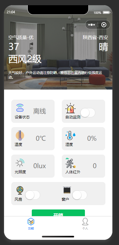
This system uses sensors for temperature, humidity, and illuminance to detect environmental information and controls drive devices to adjust accordingly, responding to environmental changes. A WeChat mini-program has been developed as the host computer, allowing remote viewing of sensor data and control of device on/off status for fans, windows, etc.
Project Functions
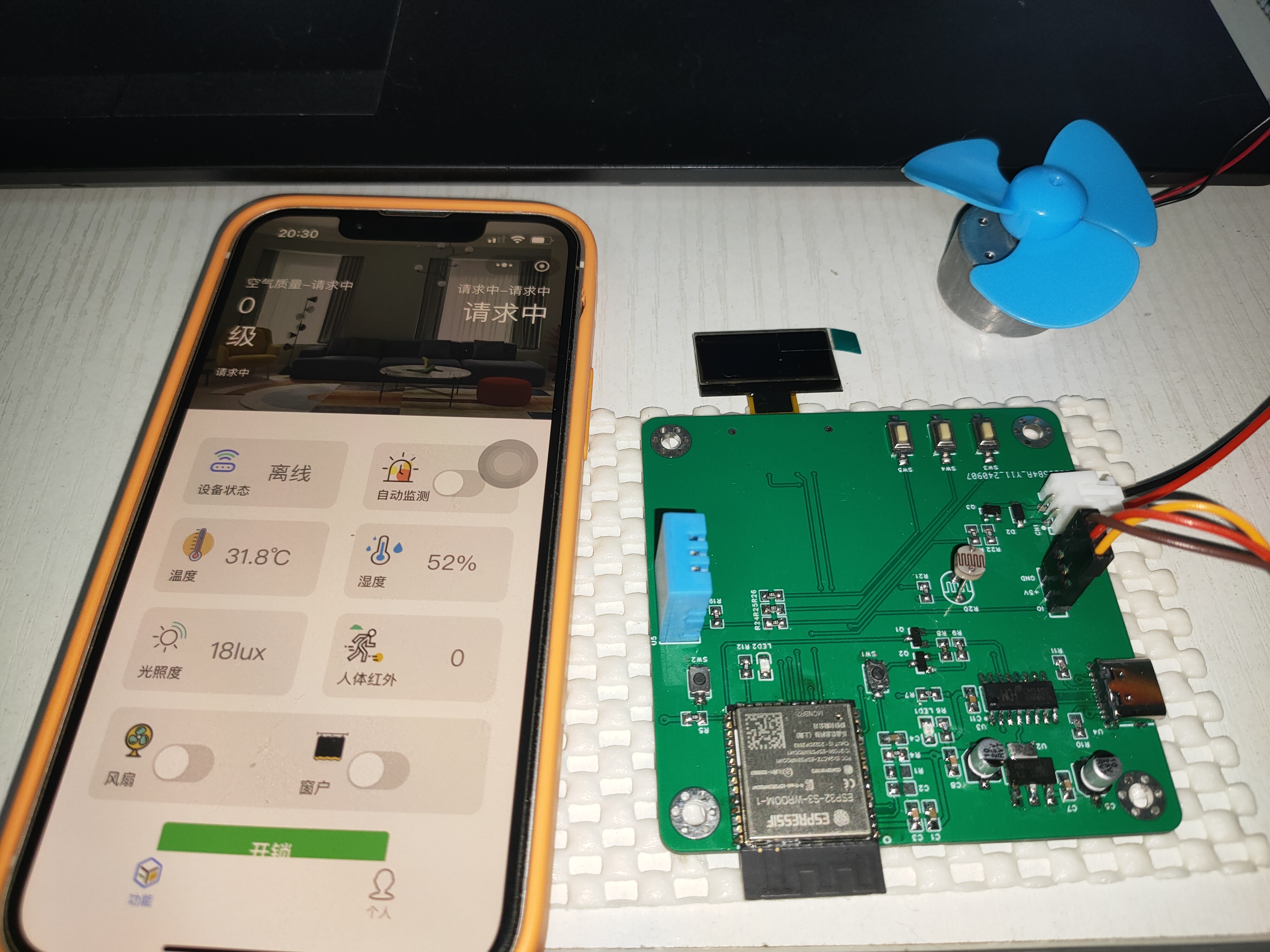
This design is a smart home monitoring system based on the ESP32; it features temperature, humidity, and illuminance sensors and three independent buttons for fan on/off, window on/off, and automatic detection on/off. When automatic detection is enabled, the fan (or window) will automatically turn on or off when the temperature, humidity, or illuminance exceeds a threshold range; when automatic detection is disabled, the switch can be manually controlled. The system features a WeChat mini-program, allowing remote viewing and modification of sensor values and system on/off status.
Project Parameters:
This design utilizes a 0.96-inch OLED display, showing the on/off status at the top and temperature, humidity, and illuminance sensor values below.
A fully digital DHT11 temperature and humidity sensor is selected, offering a wide temperature measurement range suitable for general needs.
A GL5516 photoresistor is chosen as the illuminance sensor, offering low cost and ease of implementation and portability.
Principle Analysis (Hardware Description) :
The hardware of this project consists of the following components: power supply circuit, serial port circuit, main control circuit, sensor circuit, driver circuit, and human-machine interface circuit.
1. Power Supply Circuit
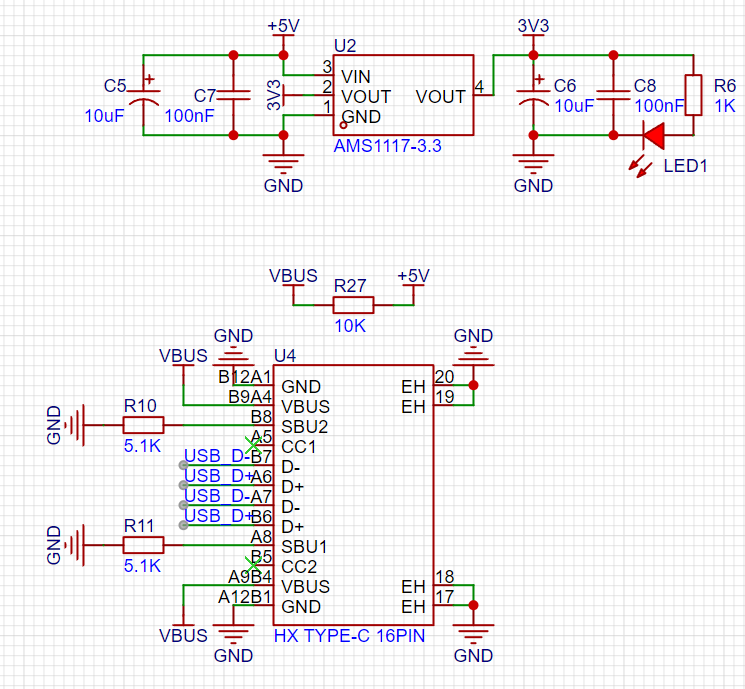
: A TYPE-C-16P interface is used as the power supply interface. The corresponding USB data pin is connected to the CH340C (to convert the USB signal to a TTL serial port signal) for downloading and debugging. The USB power supply is connected to the +5V network via R27 (actually 0R or directly shorted). Disconnecting R27 allows for external power supply to the board, enabling observation of the board's operating current and power consumption. After debugging, the board can be directly powered via USB. 1. +5V is converted to 3.3V via AMS1117 to power the ESP32 and other components.
2. The serial port circuit

uses automatic downloading, eliminating the need to press the EN and BOOT keys to program.
3. The main control circuit
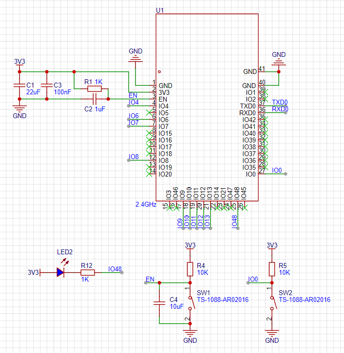
is connected according to the Espressif official manual and has been verified to work stably.
4. The

DHT11 sensor circuit communicates with the ESP32 via a single bus. A pull-up resistor needs to be added to the DATA pin to improve its driving capability.
The photoresistor uses a voltage divider to read the analog signal from the ESP32 ADC and converts it to illuminance (Lux) using a lookup table.
5. The drive circuit

uses a transistor drive circuit to control the fan switch. Note that D2 is a freewheeling diode; it needs to be soldered to prevent damage to the circuit from the reverse electromotive force caused by the fan's inductive characteristics during startup and shutdown. The power supply status can be checked with an oscilloscope; soldering D2 significantly improves power spikes.
6.

The three buttons in the human-machine interface circuit are connected to the ESP32 pins via pull-up resistors to ensure the pin level is high when the button is reset and low when pressed.

The OLED display is connected via an I2C bus as shown in the diagram.
The software code
is developed based on Arduino IDE 2.0.4 + ESP Board Pack 3.0.0. Arduino's powerful library resources can effectively reduce development workload and improve development efficiency. However, Espressif's official ESP-IDF is more helpful for understanding the underlying resources of ESP32 and FreeRTOS development, and further development will be carried out later. See the attached project
notes.
In the project's physical diagram, the OLED display is reversed; it should actually be pasted on the front of the board. This was mainly due to the initial PCB layout being drawn incorrectly, which has been corrected. However, due to time constraints, only the first version of the hardware could be demonstrated.
[Physical diagram]

New video1.mp4
ESP32IoTHome.zip
PDF_ESP32-based IoT Smart Home.zip
Altium_ESP32-based IoT Smart Home.zip
PADS_ESP32-based IoT Smart Home.zip
BOM_Based on ESP32 IoT Smart Home.xlsx
92277
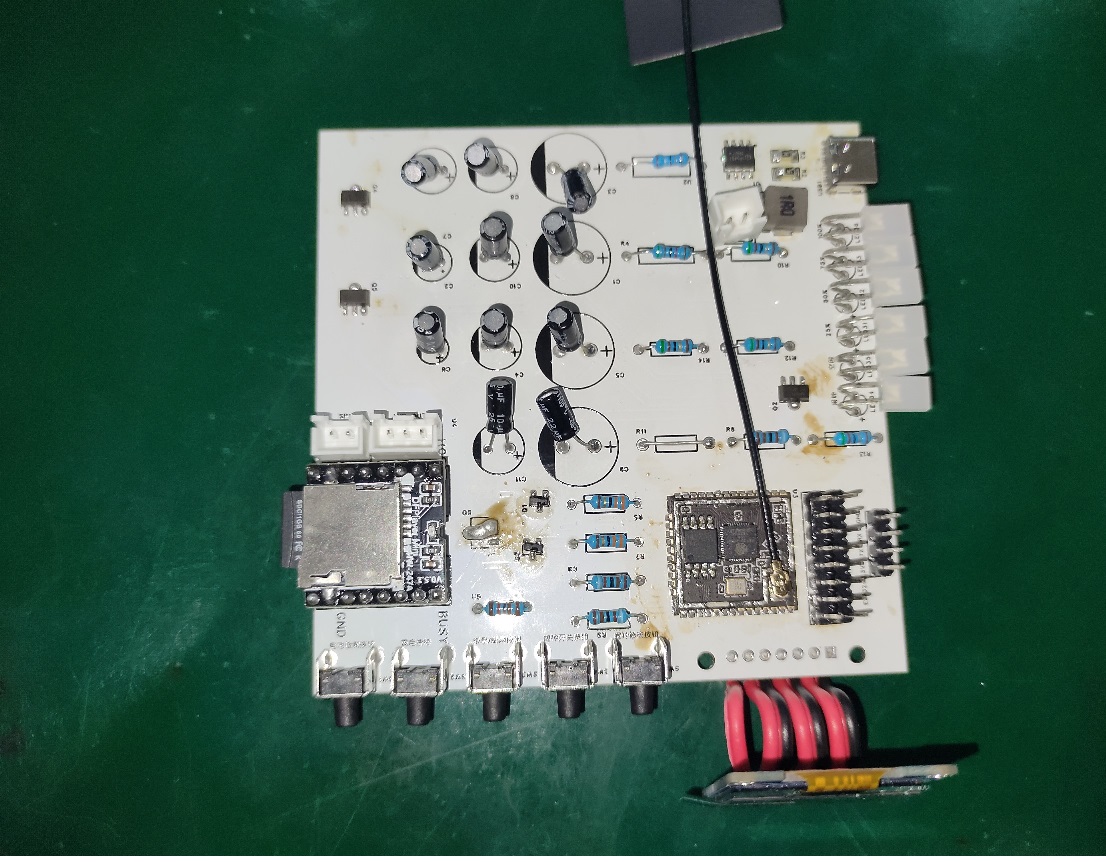
ESP32-based WIFI progressive sleep alarm clock system
The progressive alarm clock system based on the ESP32 microcontroller is an innovative product that integrates smart home technology, aiming to provide users with a more comfortable and convenient wake-up experience.

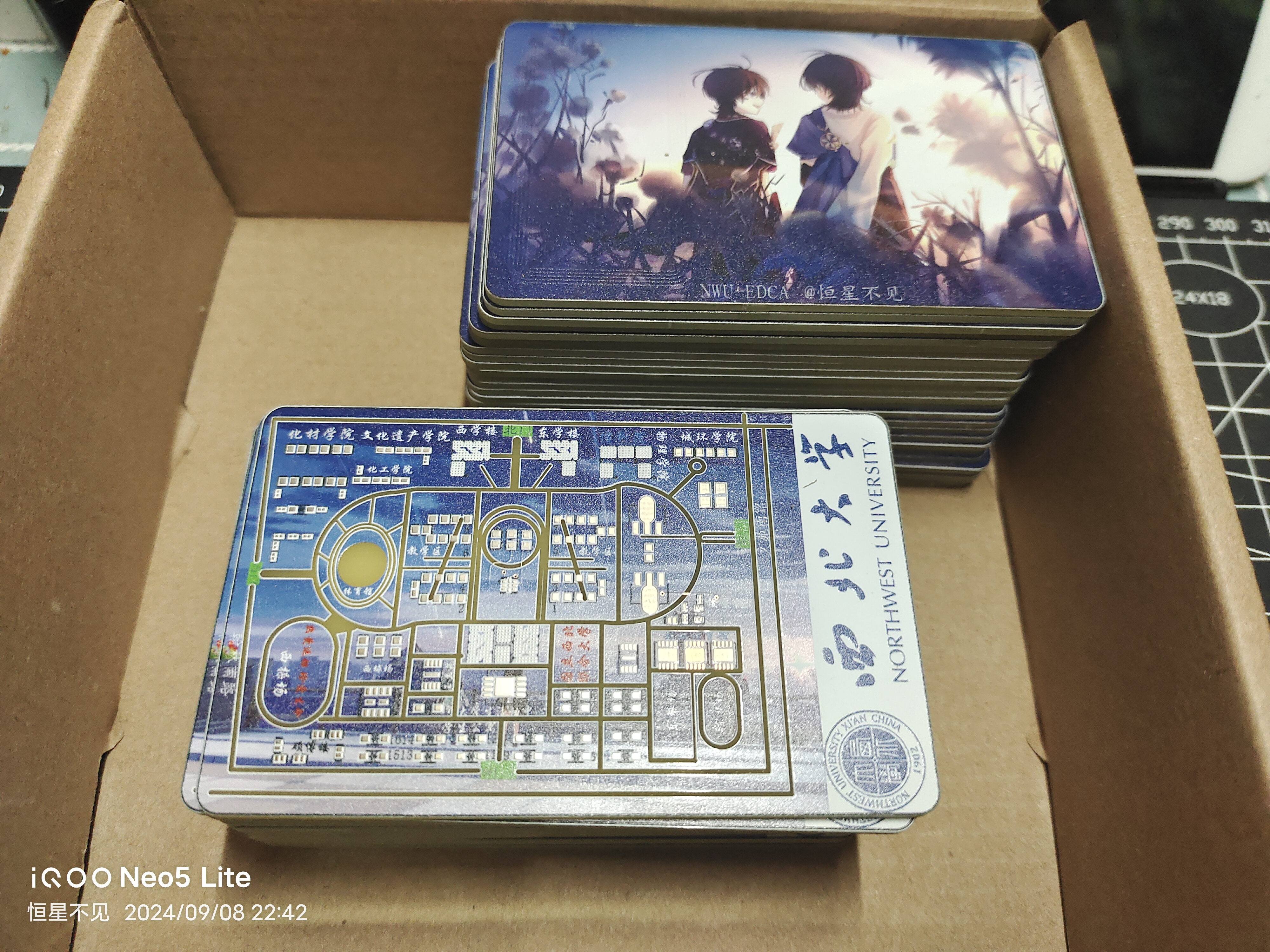
Hardware Design: Based on the high-performance ESP32 microcontroller, design and build a complete hardware system. This system will include an OLED display for clearly showing time, date, and weather information; a soft-light LED array to simulate sunrise light and help users gradually wake up; an audio decoder and speaker to play soft music to assist in waking the user; buttons for function switching, time adjustment, etc.; and a battery to ensure the system's portability and independence.

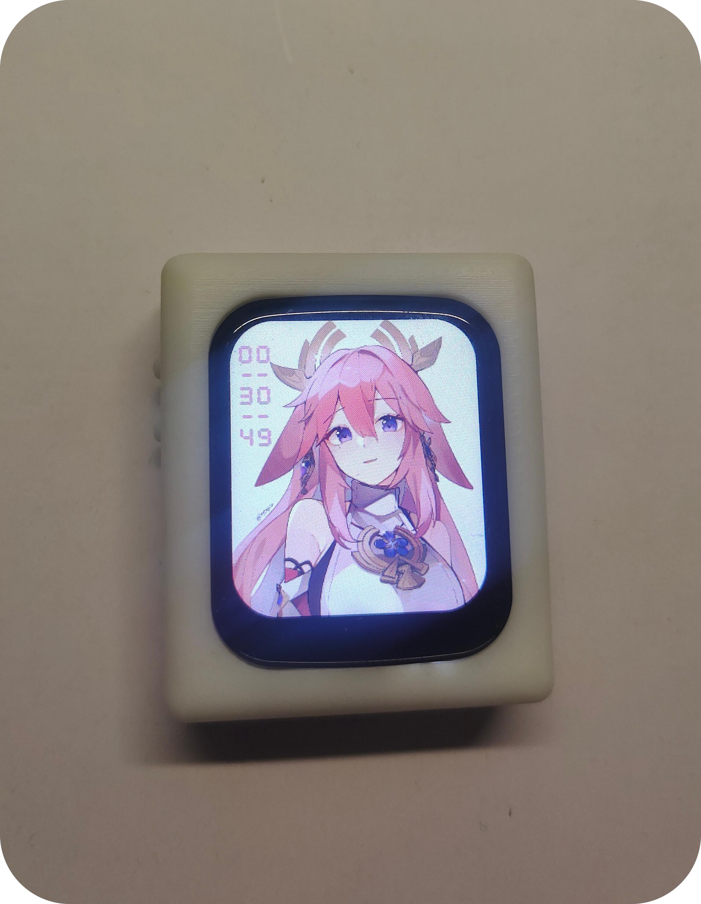
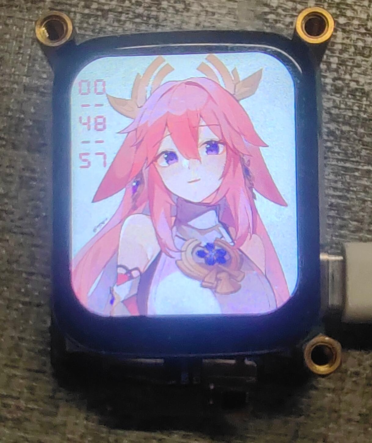
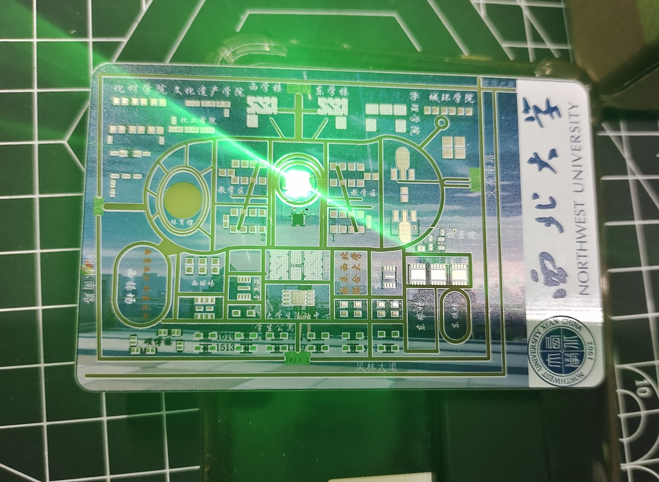
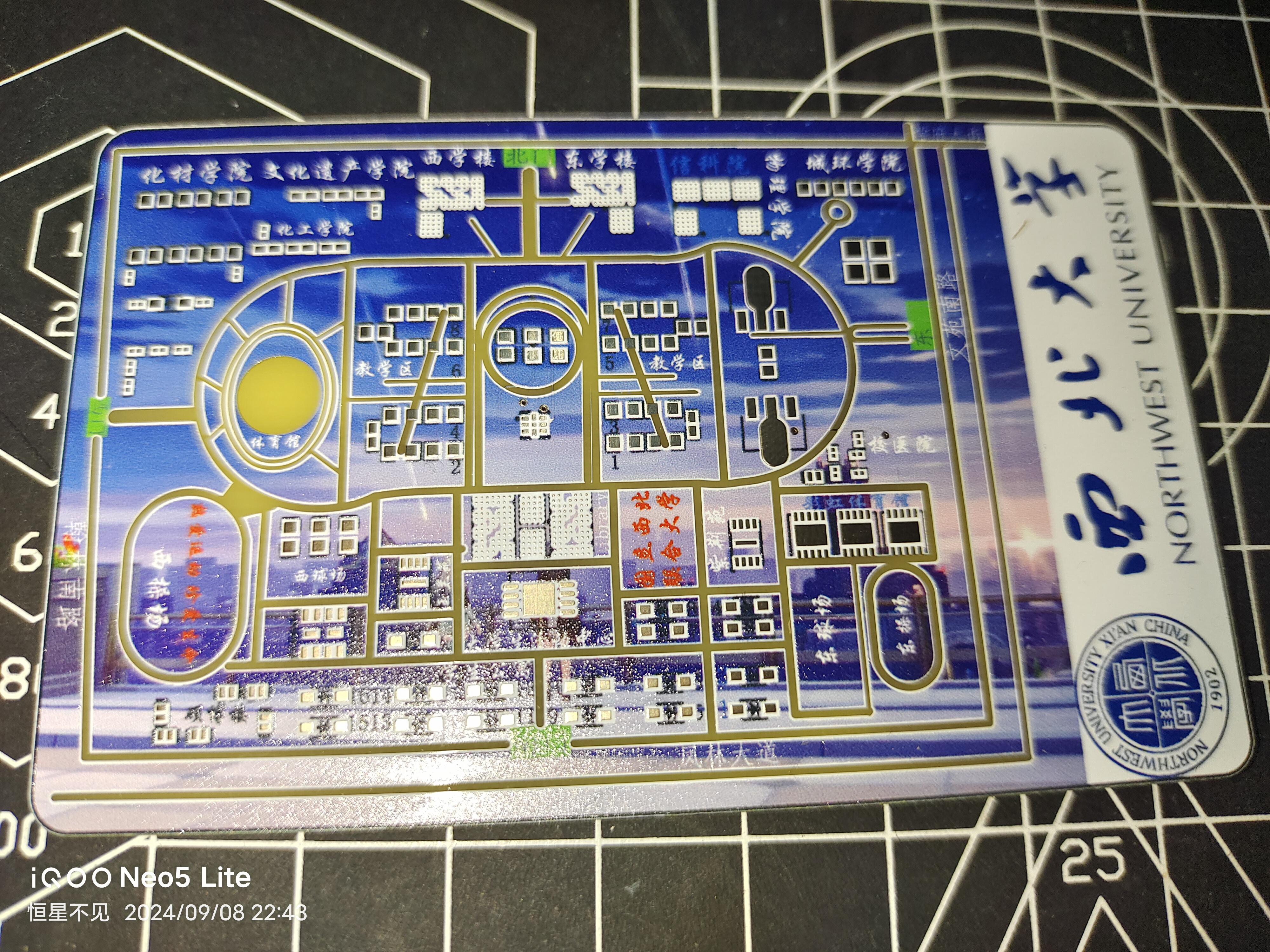
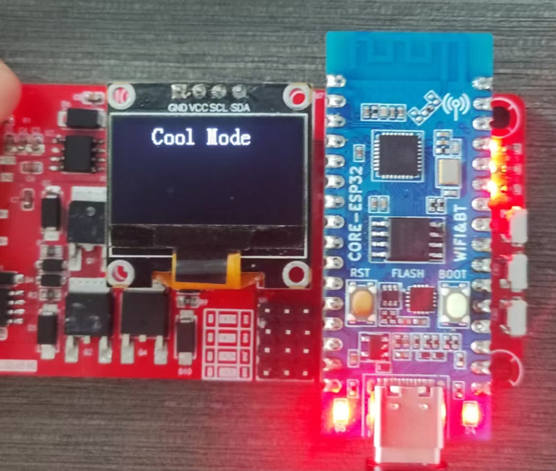
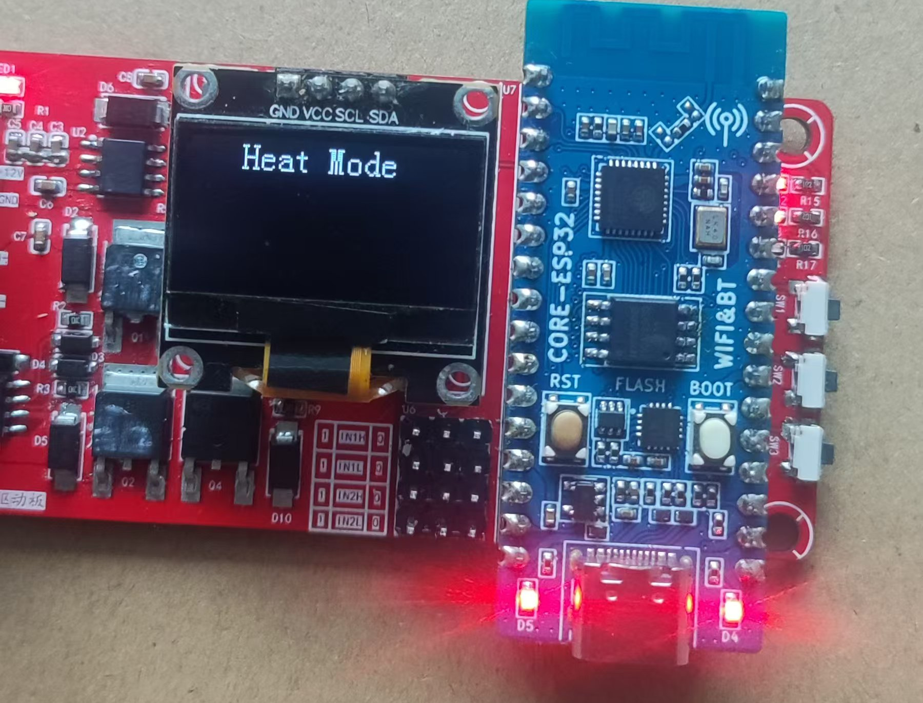
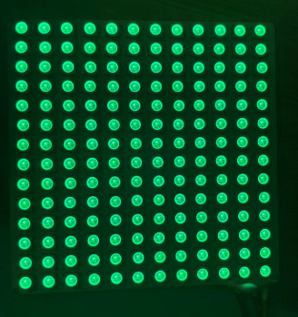
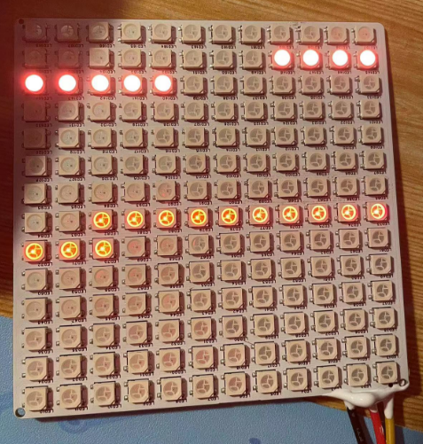
Software Design: Develop embedded software using VS Code and the Arduino environment to implement functions such as time synchronization, weather acquisition, and gradual wake-up. The software will adopt a modular design to improve maintainability and scalability. A user interface and interactive functions will also be developed to allow users to easily personalize and adjust settings. Currently, all functions work perfectly. However, when soldering, remember to reverse the Source and Ground wires of the two MOSFETs controlling the LEDs; otherwise, the LEDs will remain constantly lit and uncontrolled by the microcontroller. The image
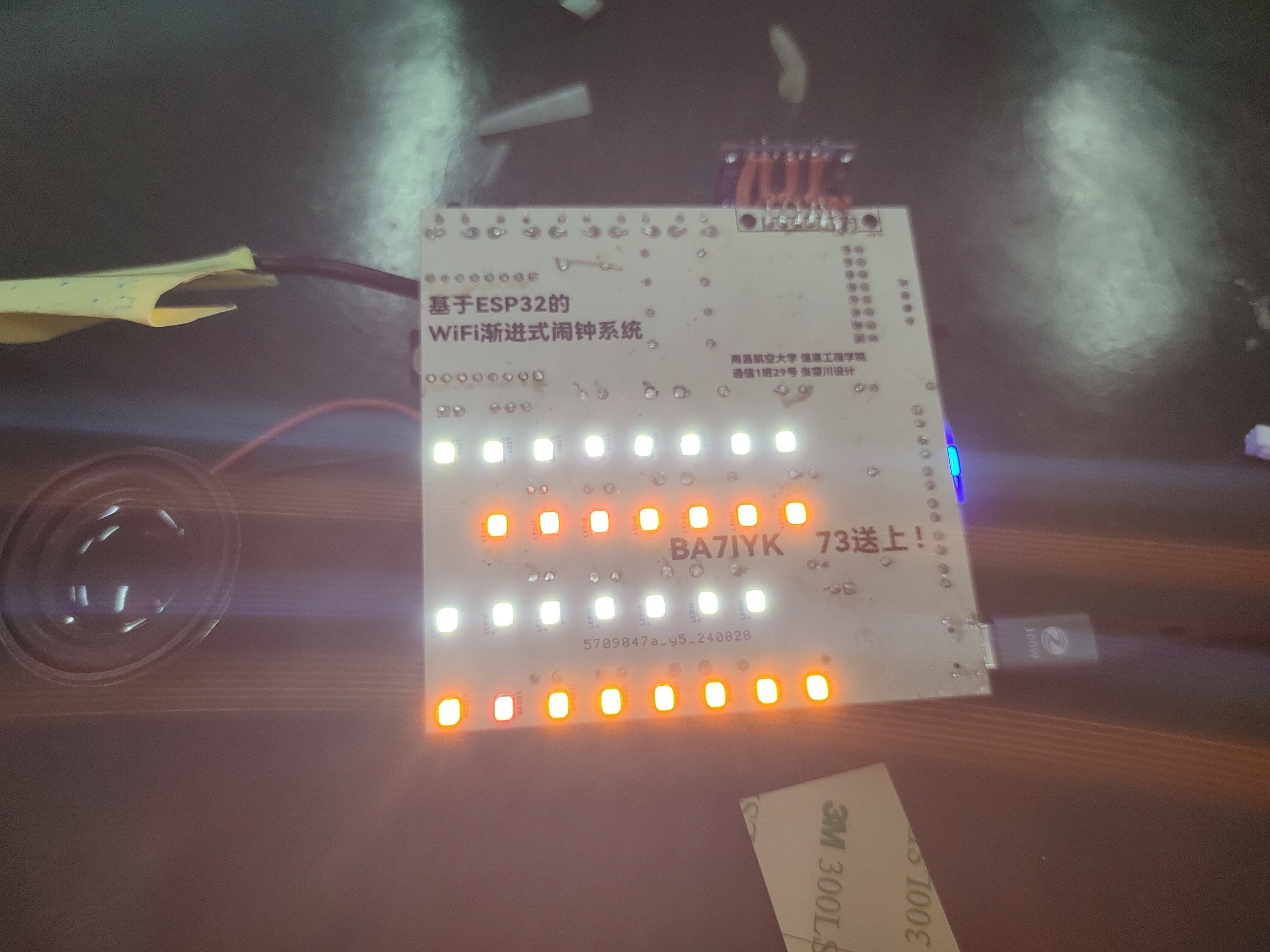
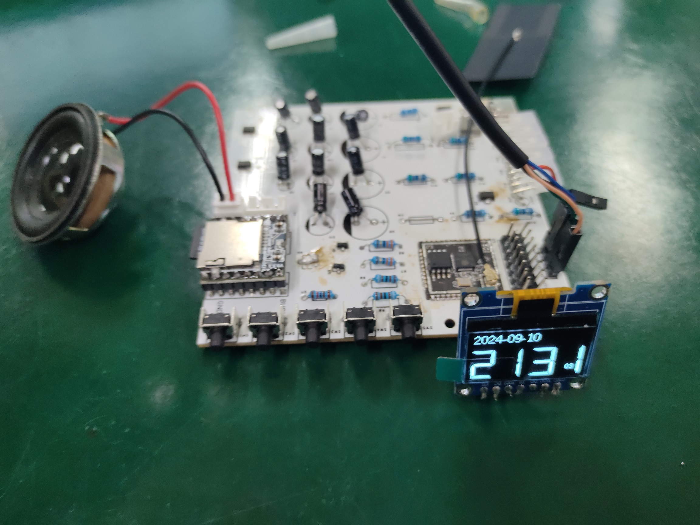
above shows the LED before the wires are reversed, meaning the LEDs are constantly lit and uncontrolled by the program. The image below shows the LED after the wires are reversed, meaning
the LEDs can be controlled by the microcontroller for switching on/off and brightness, and other functions also work perfectly.

176147cebc2d859d880e5738e466e6db.mp4
ArduinoProject.zip
PDF_ESP32-based WIFI progressive sleep alarm clock system.zip
Altium_ESP32-based WIFI progressive sleep alarm clock system.zip
PADS_ESP32-based WIFI progressive sleep alarm clock system.zip
BOM_ESP32-based WIFI progressive sleep alarm clock system.xlsx
92278
ESP32 camera
The project will use the ESP32-PICO-D4 as the core processing unit, in conjunction with the OV7670 camera module to capture images and display them on a TFT screen.
I. System Architecture
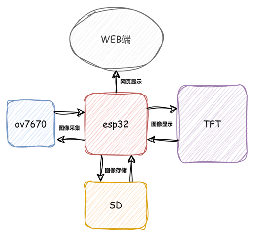
Hardware:
ESP32-PICO-D4: Responsible for image data processing, compression, and Wi-Fi communication.

OV7670 Camera Module: Responsible for capturing images from the environment.

Power Module: Provides a stable 3.3V power supply.

Software:
ESP32 Firmware: Developed using VSCode + PlatformIO, mainly responsible for initializing the camera, acquiring image data, compressing images, and displaying them on the TFT screen (web interface not yet implemented QAQ). The code isn't very good; I'll post it in the comments later.
Physical Image


II. Workflow

Image Acquisition: The OV7670 camera module captures image data and transmits it to the ESP32-PICO-D4 via a data interface.
Data Processing: The ESP32 preprocesses the image data, compressing it into a format suitable for transmission.
Data Transmission: The ESP32 sends the image data to the TFT display screen via SPI.
Image Display: The display screen receives the image data and displays it in real time.
III. Project Extension
Storage Function (To be implemented): Image data can be saved to an SD card or uploaded to cloud storage.
Motion Detection (To be implemented): Utilizes image processing algorithms to detect moving objects in the scene and trigger alarms or notifications.
IV. Project Applications
: Home Security Monitoring: Deploy cameras in the home and view real-time footage via mobile phone.
Unattended Monitoring: Remote monitoring in unoccupied areas, suitable for construction sites, warehouses, etc.
Outdoor Photography: Small, but generates a lot of heat (approximately).
camera.mp4
PDF_ESP32 camera.zip
Altium_ESP32 camera.zip
PADS_ESP32 camera.zip
BOM_ESP32 camera.xlsx
92279
ESP32 C3
Simplified version of LCSC - Practical Approach
Open source address: https://gitee.com/st7_1a/esp32-c3.git
Function introduction: (Due to shooting issues, the screen image may not be very good)
Main interface: After powering on, connect to the mobile hotspot. After a few seconds, the real-time time will be displayed in the upper left corner.
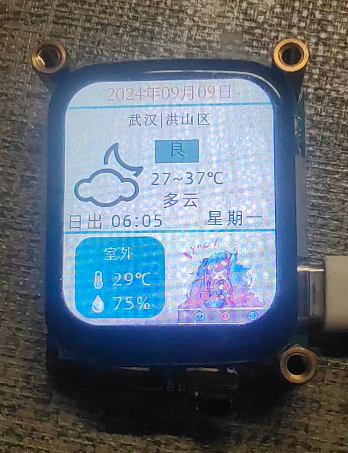
Interface 2: Displays real-time weather conditions. This part is referenced from LCSC's Practical App.
It will reconnect to the mobile hotspot every once in a while.
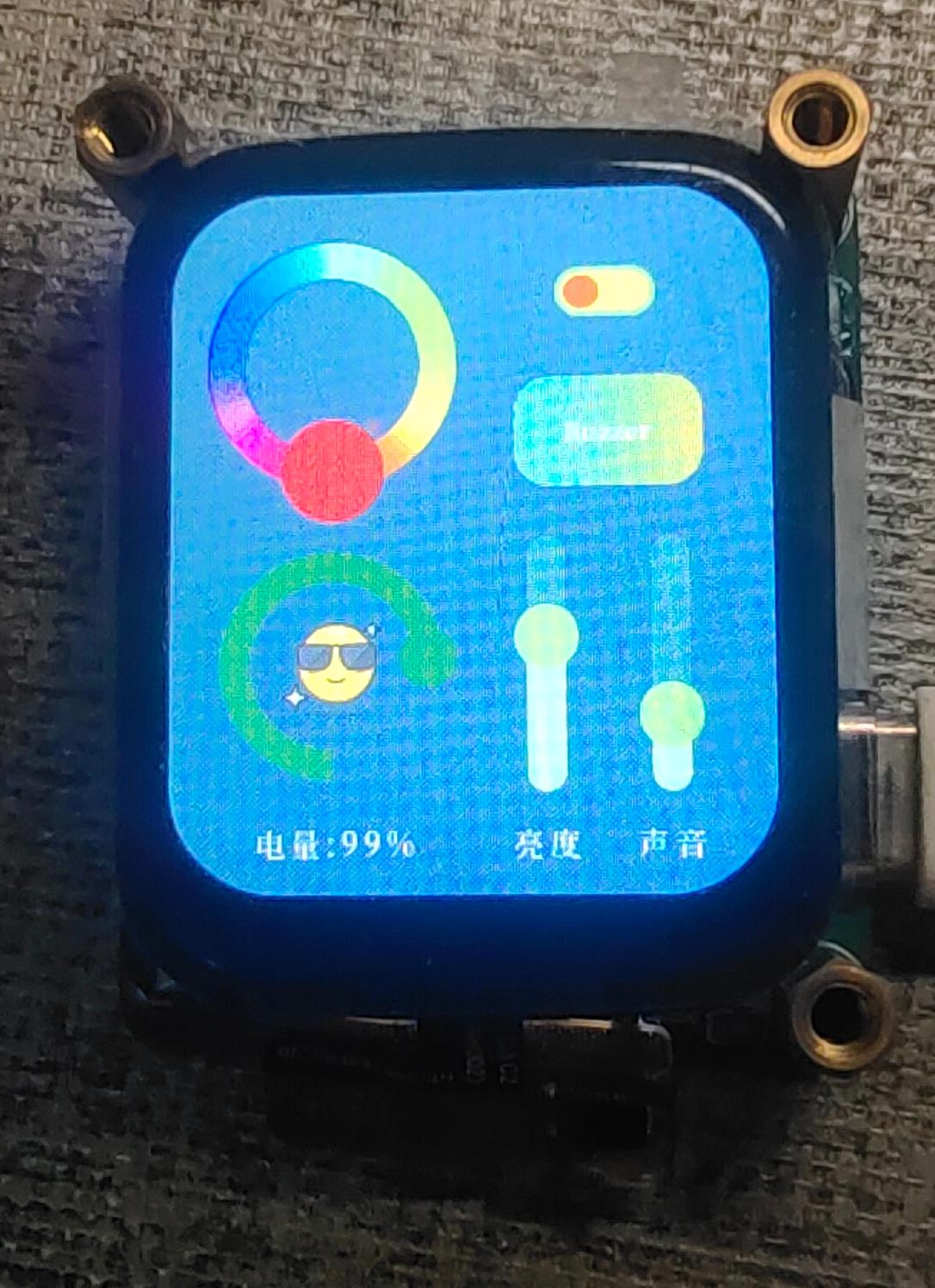
Interface 3: Functional interface
1. The color palette in the upper left corner controls the RGB lights under the board. Select any color, then long-press the blank part in the middle of the color palette to jump to the color palette from dark to light... and so on. After trying a few times, it will jump back to the initial color palette. The avocado switch controls the RGB lights to turn on and off.
2. The button in the middle on the right controls the buzzer. There are two modes: a short press makes a sound, "the middle Buzzer will change to Short".
A long press makes intermittent sounds, stopping after 5 seconds, "the middle Buzzer will change to Long".
3. The two sliders in the lower right corner control the screen brightness and volume respectively.
4. The curve in the lower left corner displays the battery level in real time.
The board also has a gyroscope and a temperature and humidity sensor, the same model as those on the LCSC Practical Edition, which are already soldered and can be used directly with the official code.

video.mp4
PDF_ESP32 C3.zip
Altium_ESP32 C3.zip
PADS_ESP32 C3.zip
BOM_ESP32 C3.xlsx
92280
ESP32-WLED Music Rhythm Light Strip
esp32+inmp441, flashed with wled software, integrated with Home Assistant to enable automatic switching of music rhythm and ambient lighting.
Project Introduction
: This section provides a basic description of the project. Example:
This project is based on ESP32 and INMP441, flashed with the WLD program, and integrated with Home Assistant to achieve automatic switching between music rhythm and ambient lighting.
Project Functionality:
The Blue Night speaker is integrated with Home Assistant. When music is played through Home Assistant, the music rhythm effect is automatically switched, and the WLD music rhythm function is enabled. When no music is playing, the ambient lighting effect is switched, and the WLD music rhythm function is automatically disabled.
Project Parameters:
This design uses the INMP441 module for easy soldering;
a 4-pin interface for easy connection to the WS28xx series;
one spare interface is reserved;
the LED strip has an independent power supply
interface. 3D shell
programming and configuration are available
at https://install.wled.me/
. Select the Audioreactive version
, connect to WiFi, enter the ESP32 IP address, open the WLEED interface
, find MQTT under Config->Sync Interfaces, open and configure the HA MQTT.
Restore my presents (wled_presets_WLED-CL.json) or create
a new automation for Bluetooth speaker volume and lighting control in HA. The attached file contains code; modify it to match your corresponding entity and WLEED MQTT theme.
Important Notes:
Only one of the independent power supply and signal line VCC can be connected. When programming
with M2*10 screws,
if only the serial port is connected and not the power supply, D2 needs to be shorted; otherwise, the voltage will be insufficient.
WeChat_20240910082720.mp4
Bluetooth speaker volume & light control.yaml
wled_presets_WLED-CL.json
PDF_ESP32-WLED Music Rhythm Light Strip.zip
Altium_ESP32-WLED Music Rhythm Light Strip.zip
PADS_ESP32-WLED Music Rhythm Light Strip.zip
BOM_ESP32-WLED Music Rhythm Light Strip.xlsx
92281
Simple voice-activated e-ink clock with one-touch countdown and alarm functions
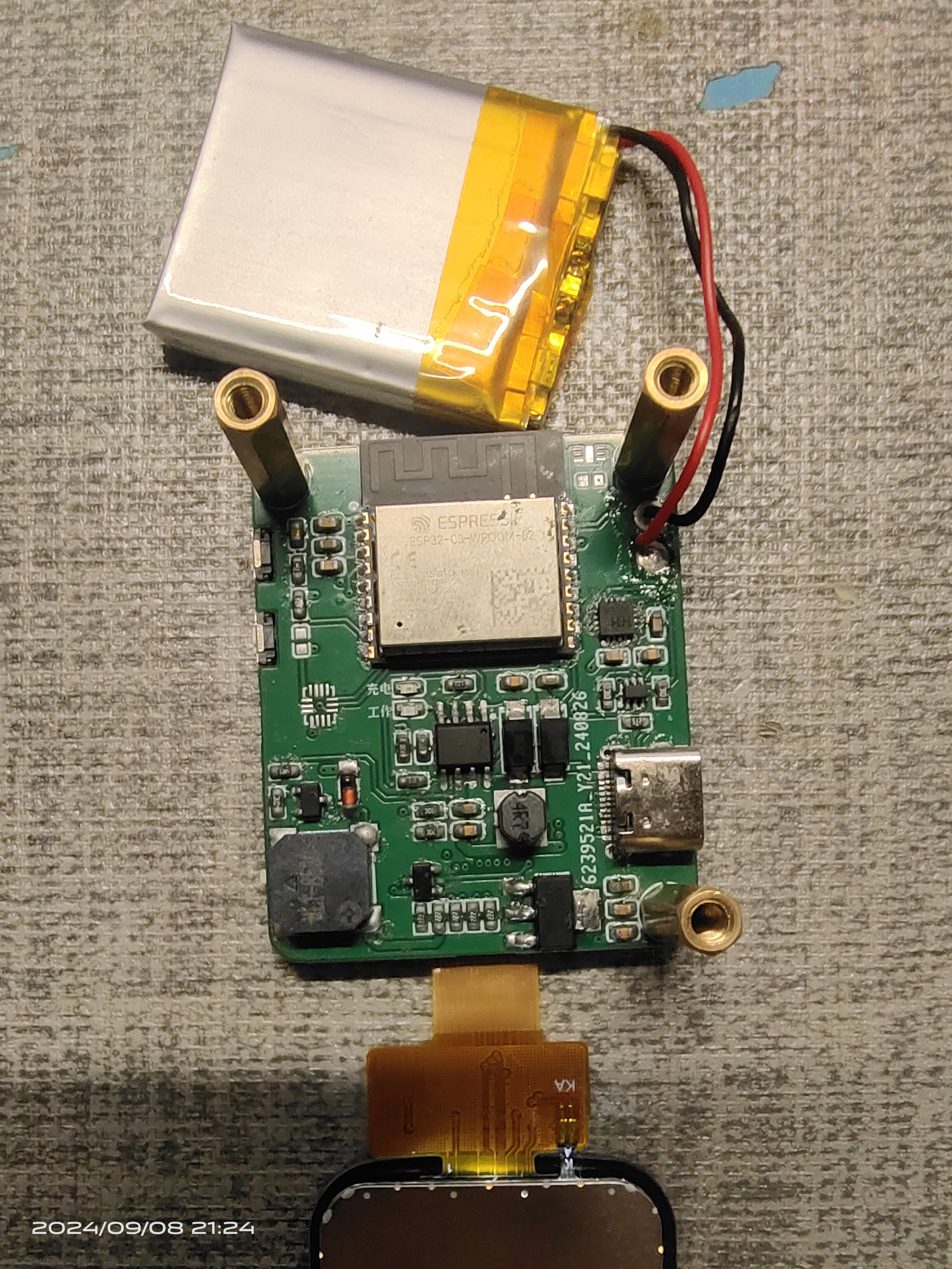
This is a pure e-ink clock based on the ESP32 chip. Its basic functions include displaying date and time, alarm clock, and countdown timer. It features a low-power design, button settings, online Wi-Fi time updates, a built-in web page for clock and time synchronization, and offline use without Wi-Fi.
This is a pure e-ink clock based on the ESP32 chip, featuring basic alarm clock, one-button countdown, and voice-activated alarm settings. It boasts a low-power design, allows for online Wi-Fi time updates, and has a built-in web page for clock and time synchronization. It can
also be used offline without Wi-Fi. Many open-source e-ink clocks offer a wide range of features, but my requirements are simple: a basic clock display, alarm, and timer functions, while also considering power consumption, offline usability, and easy time setting.
Therefore, I designed this clock using the ESP32-WROOM-32D as the main controller. The ESP32 has abundant available I/O, and the peripheral circuitry only includes automatic downloading, lithium battery charging, an 8025 clock chip, a buzzer, e-ink driver, and button circuitry. The circuit is relatively simple and easy to replicate. The cost is also low; the main components are the ESP32 module and the e-ink screen. The 8025 clock chip is inexpensive and cost-effective. Without the ASRPRO offline voice module, the total cost should be below 30 yuan.
Low-power design: Upon power-on and connecting to Wi-Fi to update the time, the ESP32 enters Deepsleep mode. The 8025 clock chip generates an interrupt every minute to wake the ESP32 and update the e-ink display. After the update is complete, it immediately enters Deepsleep mode again. After pressing the settings button, wait only 2 minutes before automatically entering Deepsleep mode. Connecting to the built-in webpage to set the time and alarm must be completed within 2 minutes. Power is only supplied to the offline voice module after pressing the voice button. After 15 seconds of power supply, it automatically shuts off and enters Deepsleep mode. Voice commands must be spoken 3 seconds after pressing the button and completed within 15 seconds!
In testing, the time was updated via Wi-Fi once a week or once a month, and the time display remained very accurate. Therefore, the power consumption is mainly limited to the 8025 clock chip and the e-ink display. The 1000mAh battery has been tested for a month and still has power!
For a demonstration video, please visit Bilibili: https://www.bilibili.com/video/BV1664nenEhg
Known issue:
After pressing the voice button and powering on the offline voice module, it takes 2-3 seconds for the voice command to be recognized. This is likely due to a startup and loading time for the voice module.
After connecting via the clock's access point (AP), the webpage updates the time from 2024, but the clock displays 2042. What kind of bug is this?
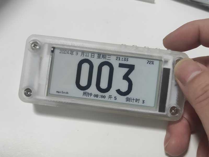
Implemented features include:
1. Basic time display, alarm clock, and countdown reminder;
2. Network NTP time update function;
3. When there is no Wi-Fi, connecting to the clock AP and using the built-in webpage to synchronize time;
4. Button-based alarm and countdown
time setting function; 5. Clock's built-in webpage for setting alarm and countdown time
; 6. Selectable network time update frequency or no network time update function;
7. One-click countdown start function;
8. Offline voice setting of alarm and countdown time function; (optional function)


The five buttons' layout and functions:
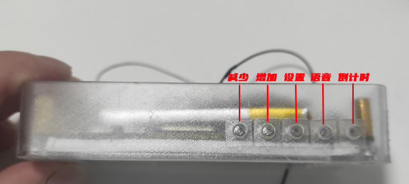
Pressing the set button will cycle through five configurable items: alarm hour, minute, alarm on/off, alarm mode, and countdown time. Pressing the increase and decrease buttons adjusts the value of the selected item. When the clock is in setup mode, it will simultaneously turn on its Wi-Fi and connect to the designated Wi-Fi network. Once connected, the clock's IP address will be displayed in the lower left corner. If not connected to Wi-Fi, the clock will create a hotspot named "myclock"

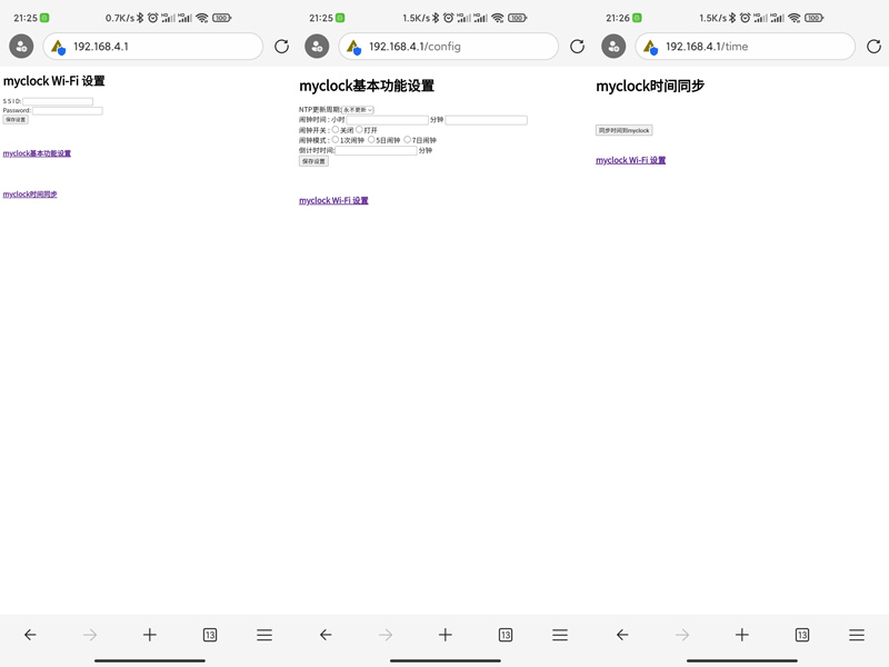
. After connecting to the "myclock" hotspot, access the settings page at 192.168.4.1. You can then access the following three built-in clock settings pages: Wi-Fi settings; clock, alarm, and countdown settings; and time synchronization.
One-click countdown function:
Alarm and countdown times can also be set offline via voice. For a demonstration, please see the demo video on Bilibili.
The voice function uses the ASRPRO offline voice module, and the programming software is Tianwen Block .
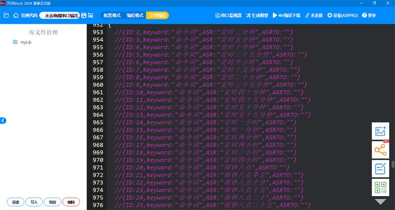
The ESP32 program uses the Arduino language, and the development tools are VSCode + Platformio.
The ESP32 source code, ASRPRO source code, and compiled firmware are all uploaded as attachments. The ASRPRO module firmware can be uploaded using Qiying Tailun's programming tool!
EDP_Test2.zip
esp32bin.zip
asrproCode.zip
asrprobin.zip
PDF_Simple Voice E-ink Clock with One-Touch Countdown and Alarm Functions.zip
Altium - A simple voice-activated e-ink clock with one-touch countdown and alarm functions. (zip)
PADS - A simple voice-activated e-ink clock with one-touch countdown and alarm functions. zip
BOM_Simple Voice E-ink Clock with One-Touch Countdown and Alarm Functions.xlsx
92282
electronic


 Principle Analysis (Hardware Description)
 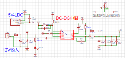 Example Figure 1 -- Power Supply Circuit:
  1. Check the SW4 toggle switch; its application in the ESP32 module enables USB serial port data download. 1. When no external power is connected, the switch is in the "up" position. The USB provides power to the DC-DC chip, enabling the CH343P to be correctly powered and download firmware (the ESP8266 needs to be programmed first, ensuring the ESP32_EN pin is high and the ESP32 module is powered on).


 京公网安备 11010802033920号

 IRHF93230


