be within 0.2C. Unless specified in the datasheet, do not take risks (mAh capacity × 0.2C = charging current mA).
A TVS switch is necessary; otherwise, the IP2312 rating will be damaged.
The maximum charging voltage is 4.2V.
The inductor will generate significant heat during charging; handle with care to avoid burns.
[Casing Verification + Minor Optimization] PCB Lighting Design - Ultimate Enhanced Pro+
The outer shell of the "PCB Lighting Art - Ultimate Enhanced Pro" project has been verified, and minor optimizations have been made. Open source makes the world a better place!!
Verification Project PCB Lighting Project - Ultimate Enhanced Version Pro - JLCPCB EDA Open Source Hardware Platform (oshwhub.com) -----------------------------------------------------------------------------------------------------------------------------------------------------
Thanks to the open source project author for providing the model. The following improvements have been made to this version:
1. Corrected the PCB orientation error of the TP4056 charging indicator light in the original project (the silkscreen of the red LED indicator light on the original PCB was reversed).
2. Added a sampling capacitor pad position for easier touch sensitivity tuning.
3. Changed the current-limiting resistor value of the LED, so the total current will be less than 600mA (the limit of the BOOST boost chip).
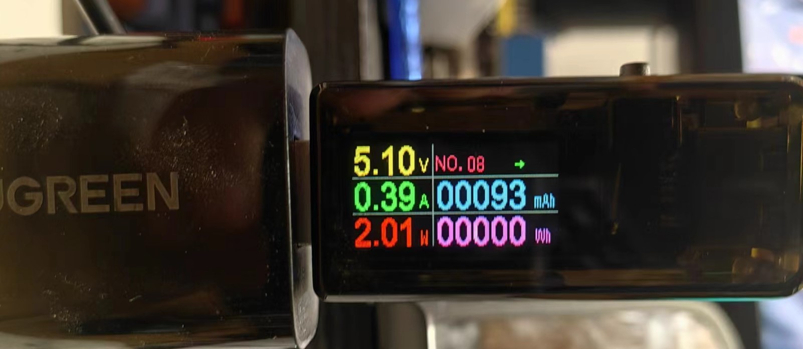
4. Reset the resistance value of R25 so that the charging current can reach 400mA.
-----------------------------------------------------------------------------------------------------------------------------------------------------
Production Experience:
One day I saw a PCB light on a certain website, which happened to be available on the open source platform: PCB Lighting Project Night Light - A perfect combination of art and technology to illuminate the dark path of life. JLCPCB EDA open-source hardware platform (oshwhub.com).
However, after searching on the JLCPCB open-source hardware platform, I found the best-looking one (as of May 1, 2024): PCB Lighting Artwork (Framed Version) - JLCPCB EDA Open-Source Hardware Platform (oshwhub.com).
But printing the framed version on 3DMark costs 140 RMB, while having the framed version creator print it for 60 RMB. However, the creator prints it themselves and also assembles the outer casing. I'm rather lazy, so I ended up finding this unverified option.
Then I checked on 3DMark.com and saw that the unverified white casing was only 50 RMB, and the translucent one was over 60 RMB, so I decided to try verifying it myself.
-----------------------------------------------------------------------------------------------------------------------------------------------------
Casing Description:
Because I increased the current-limiting resistor for the LED, the brightness decreased slightly. Adding a diffuser didn't seem to work well, so I just shoved the PCB in. Don't ask how I did it; just use brute force!

Then I glued the battery to the back.

The casing is a bit thick, but once the switch is on, it basically doesn't need to be turned off. It's 4000mA, what more could you ask for ?
-----------------------------------------------------------------------------------------------------------------------------------------------------
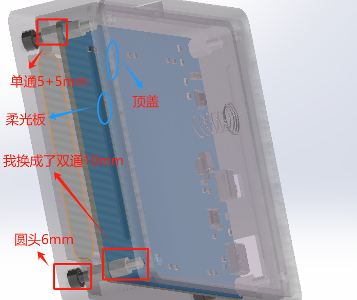
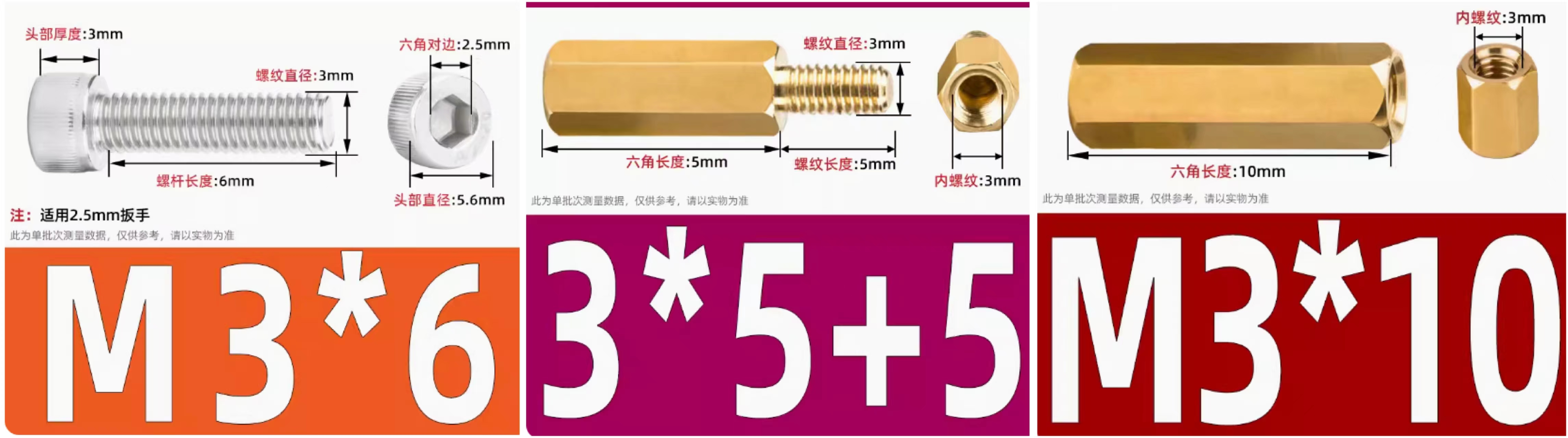
Key Material Purchase Links:
Screws: https://detail.tmall.com/item.htm?_u=c3q1203894bf&id=529586487467&spm
Copper Pillars: https://detail.tmall.com/item.htm?_u=c3q1203847f3&id=19634185206&spm
https://detail.tmall.com/item.htm?_u=c3q12038af09&id=41574313055&spm
Ceramic Lamp (26mm Gold Warm Light + White Light): https://item.taobao.com/item.htm?_u=c3q120388a42&id=657899815261&spm
Battery (606090 [4000mAh] 2.54 Red and Black): https://item.taobao.com/item.htm?_u=c3q12038274d&id=528235852444&spm
-----------------------------------------------------------------------------------------------------------------------------------------------------
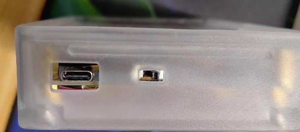
Order the casing; you can choose between LEDO6060 or 8001 (I chose the 8001 semi-transparent one on the right; it's a bit sharp on the hand, but sandpaper is included so you can sand it yourself).

-----------------------------------------------------------------------------------------------------------------------------------------------------
Finished Product Showcase (White, Warm, Warm White)


-----------------------------------------------------------------------------------------------------------------------------------------------------
Conclusion: The reason I made this PCB drawing light is to give it to a girl (a junior high classmate I've known for almost eight years). Since graduation, we've exchanged gifts every year on each other's birthdays. I remember two years ago, I made her a PCB heart-shaped light, and last year I just bought her snacks as a gift.
This year, she's graduating again, and I wanted to make something related to my professional field, regardless of cost (this project probably took about one sheet to complete; if I used a rolled-up drawing, it probably wouldn't even cost one sheet, hahaha). Then I came across this PCB drawing light, and as you all know, I made it, hehehe~.
If you also like this light, then hurry up and make one for someone you "love," especially if you have a partner.
Oh, by the way, I'm single too.
Here's the link to the original project again: PCB Light Drawing - Ultimate Enhanced Pro - JLCPCB EDA Open Source Hardware Platform (oshwhub.com)
ProProject_【Casing Verification + Minor Optimization】PCB Lighting Design - Ultimate Enhanced Pro+_2024-05-12.epro
PDF_【Casing Verification + Minor Optimization】PCB Lighting Design - Ultimate Enhanced Version pro+.zip
Altium_【Casing Verification + Minor Optimization】PCB Lighting Design - Ultimate Enhanced Version pro+.zip
PADS_【Casing Verification + Minor Optimization】PCB Lighting Design - Ultimate Enhanced Version pro+.zip
BOM_【Casing Verification + Minor Optimization】PCB Lighting Design - Ultimate Enhanced Version pro+.xlsx
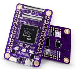
It uses ESP32 as the main controller, supports DAPLink debugging, and supports TTL, RS232, RS485, and RS422 communication testing.
I came across ylj2000's high-speed wireless DAP debugger Lite on an open-source platform, and it seemed pretty good, so I studied it. However, since I usually use RS232 or RS485 for debugging in my projects, I added RS232, RS485, and RS422 communication extensions to the original solution. It has been prototyped and tested, and the functionality is stable.
I'm sharing it for everyone to exchange and learn from. Commercial use is prohibited without the author's permission.
Original project author information:
https://oshwhub.com/ylj2000/dap_hs_esp_open
Updated the programmer PCB layout, preparing to create a 3D casing. Discussions and guidance are welcome. (Only group: 289917684) The previous schematics were old; the current version is identical to the images.
![QQ screenshot 20240508142451.jpg]

Sakaban Turtle Smart Edition Resource Pack.zip
PDF_Sakaban Turtle Smart Edition.zip
Altium_Sakaban Turtle Smart Edition.zip
PADS_Sakaban Turtle Smart Edition.zip
BOM_Sakaban Turtle Smart Edition.xlsx
94853
Zhengdian Atom STM32MINI OLED Interface Circuit Board
OLED interface circuit board for Zhengdian Atom STM32F103MINI development board
This is a circuit board for the STM32F103MINI development board from Zhengdian Atom, featuring an OLED interface. It includes: 1. IIC and SPI interfaces; 2. 8 LED test I/O ports; 3. Two types of IIC interfaces are available; pay attention to the VCC and GND order; 4. The purpose is to facilitate use with 0.96" and 1.69" OLED displays, allowing for direct plug-and-play functionality.
PDF_Zhengdian Atom STM32MINI OLED Interface Circuit Board.zip
Altium_正点原子STM32MINI OLED Interface Circuit Board.zip
PADS_Zhengdian Atom STM32MINI OLED Interface Circuit Board.zip
BOM_Zhengdian Atom STM32MINI OLED Interface Circuit Board.xlsx
94854
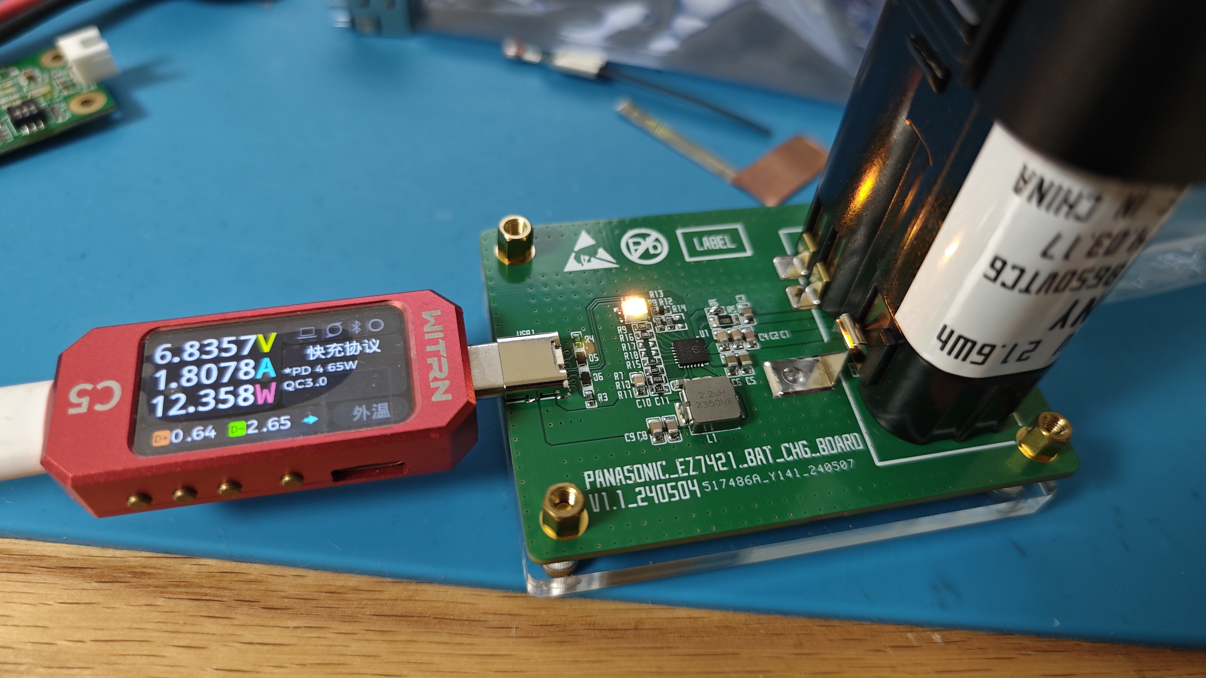
Panasonic EZ7421/EZ7521 Battery Charging Board - IP2326 Version
The battery charging board based on Ingenic IP2326 is designed for the 7.2V battery packs of Panasonic EZ7421 and EZ7521, making it easy to carry and its functionality has been verified.
1. Based on the existing open source, the battery interface has been designed to be EZ7421/EZ7521;
2. The battery insert packaging has been modified, but the device 3D model is still the original, so the 3D preview is incorrect, please ignore it;
3. When soldering the spring contacts, the distance between the spring contacts is finely adjusted according to the tightness.
Gerber_Panasonic EZ7421_EZ7521 Battery Charging Board_2024-05-11.zip
BOM_Panasonic EZ7421_EZ7521 Battery Charging Board_2024-05-11.xlsx
PDF_Panasonic EZ7421-EZ7521 Battery Charging Board - IP2326 Version.zip
Altium_Panasonic EZ7421_EZ7521 Battery Charging Board - IP2326 Version.zip
PADS_Panasonic EZ7421_EZ7521 Battery Charging Board - IP2326 Version.zip
BOM_Panasonic EZ7421_EZ7521 Battery Charging Board - IP2326 Version.xlsx
94855
STLink-v2.1 (Virtual Serial Port + USB Flash Drive Burning)
Stlink with virtual serial port, supporting drag-and-drop programming from USB flash drive.
In embedded development, a debugger is an indispensable tool.
While Daplink is widely used, its support for new ST features (such as CubeIDE and STM Studio) is not very friendly. However, most of the inexpensive ST-Links available online are version 2, which does not support serial ports and uses cheap, ground-out chips or domestically produced chips, resulting in poor stability. With ST chip prices currently falling, building an inexpensive ST-Link v2.1 debugger is a good option!
Project Overview:
1. This ST-Link v2.1 debugger was designed using LCSC EDA Professional Edition, complying with free prototyping rules;
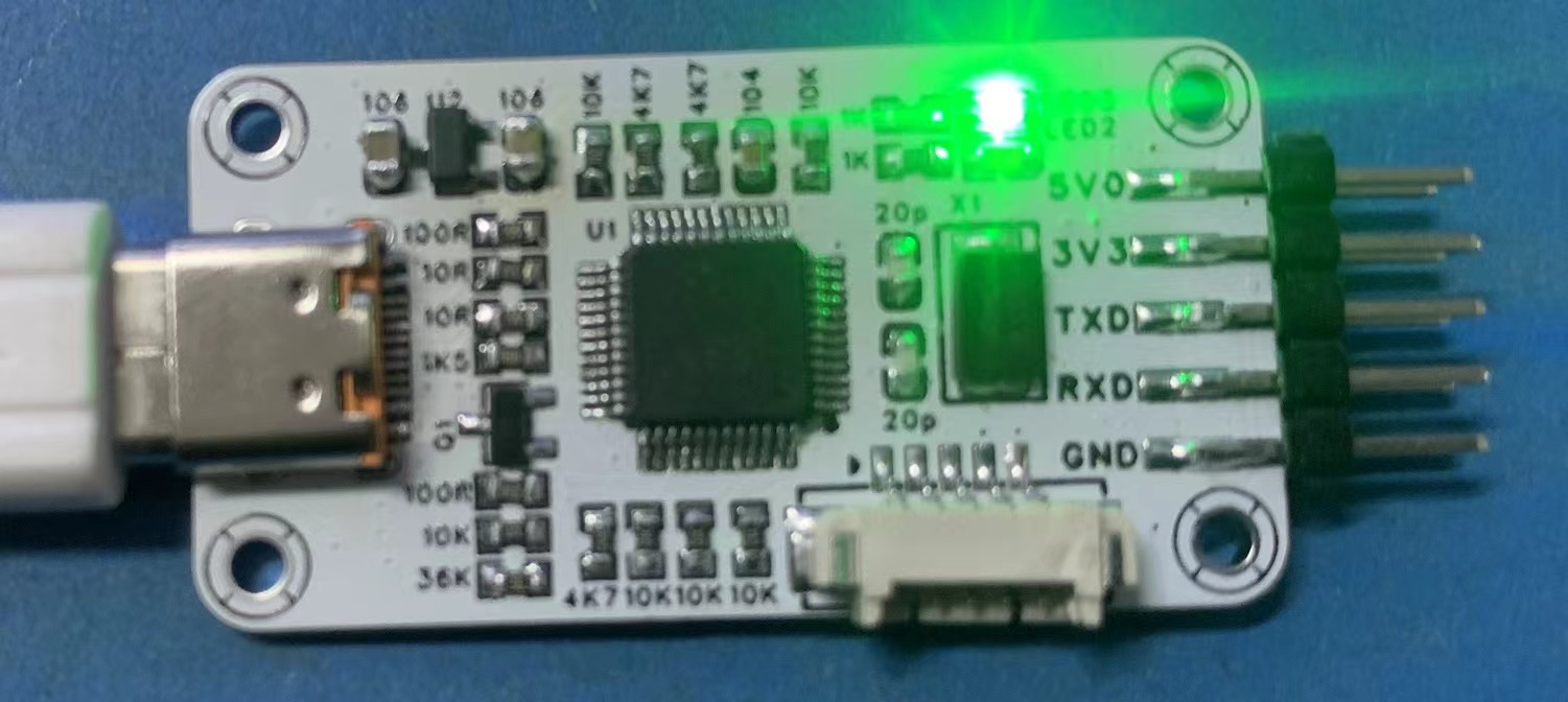
2. The debugger uses a Type-C interface and supports C-to-C cables (a 5.1k resistor on the back of the Type-C interface needs to be soldered according to the BOM);
3. The entire debugger board is only 40mm*20mm in size, and all resistors and capacitors use 0603 packages, ensuring a compact size and simple soldering;
4. The debugger has clearly marked component information, allowing for easy soldering without referring to the schematic!
BOM Cost Overview:
STM32F103CBT6: Average price on Taobao < ¥6
3.3V-LDO: ≈ ¥0.5
Resistors, Capacitors, LEDs, Pin Headers, Terminals, Transistors: ≈ ¥3
PCB: JLCPCB free prototyping ¥0
Overall BOM Cost: < ¥10
Firmware Burning Method (STM32CubeProgrammer):
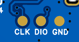
1. Connect the probes of the downloader to the pads on the back of the PCB.
2. After burning the program using CubeProgrammer,

the serial port and debugger will be recognized.
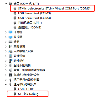
The LED will light up after successful enumeration, and the computer will recognize the USB drive.
Precautions:
1. CBT6 must be used; C8T6's Flash size is insufficient for downloading.
2. After downloading the firmware, you can use STM32 ST-LINK Utility for online firmware updates.
3. Due to size limitations, this STLink does not have overcurrent protection circuitry. After manual soldering, please ensure there are no short circuits before powering on to avoid burning out the computer's USB port.
STLinkV2.J28.M18 stlink_CB.bin
PDF_STLink-v2.1 (Virtual Serial Port + USB Flash Drive Burning).zip
Altium_STLink-v2.1 (Virtual Serial Port + USB Flash Drive Burning).zip
PADS_STLink-v2.1 (Virtual Serial Port + USB Flash Drive Burning).zip
BOM_STLink-v2.1(Virtual Serial Port + USB Flash Drive Burning).xlsx
94860
6-channel magnetic latching relay switch with metering - espc3
6-channel magnetic latching...
Special Note: This project involves 220V high-voltage electricity. Although the neutral wire is used as the reference ground, touching the low-voltage parts will not cause death. However, since there is no isolation, accidentally reversing the live and neutral connections is still quite dangerous. If you need to replicate this, please be extremely careful!!
I previously made this [Smart Home] 6-way WiFi controller with metering - JLCPCB EDA open-source hardware platform (oshwhub.com),
and it worked very well without any problems. However, for some unknown reason, the corresponding relay of the bathroom heater light might stick. I replaced the relay twice, but the problem persisted...
So I thought about making a new one... Then I wanted to try the highly praised magnetic latching relay... So I designed this board.
Compared to the previous version, this time I used the ESP32-C3-MINI as the main controller (if the ESP32 doesn't use the S2 or S3... the I/O seems insufficient), so I used the PCF8575TS for I/O expansion. The power metering continues to use the BL0942.
The CN8023B is used to drive the FH44L-1AT-L1 magnetic latching relay.
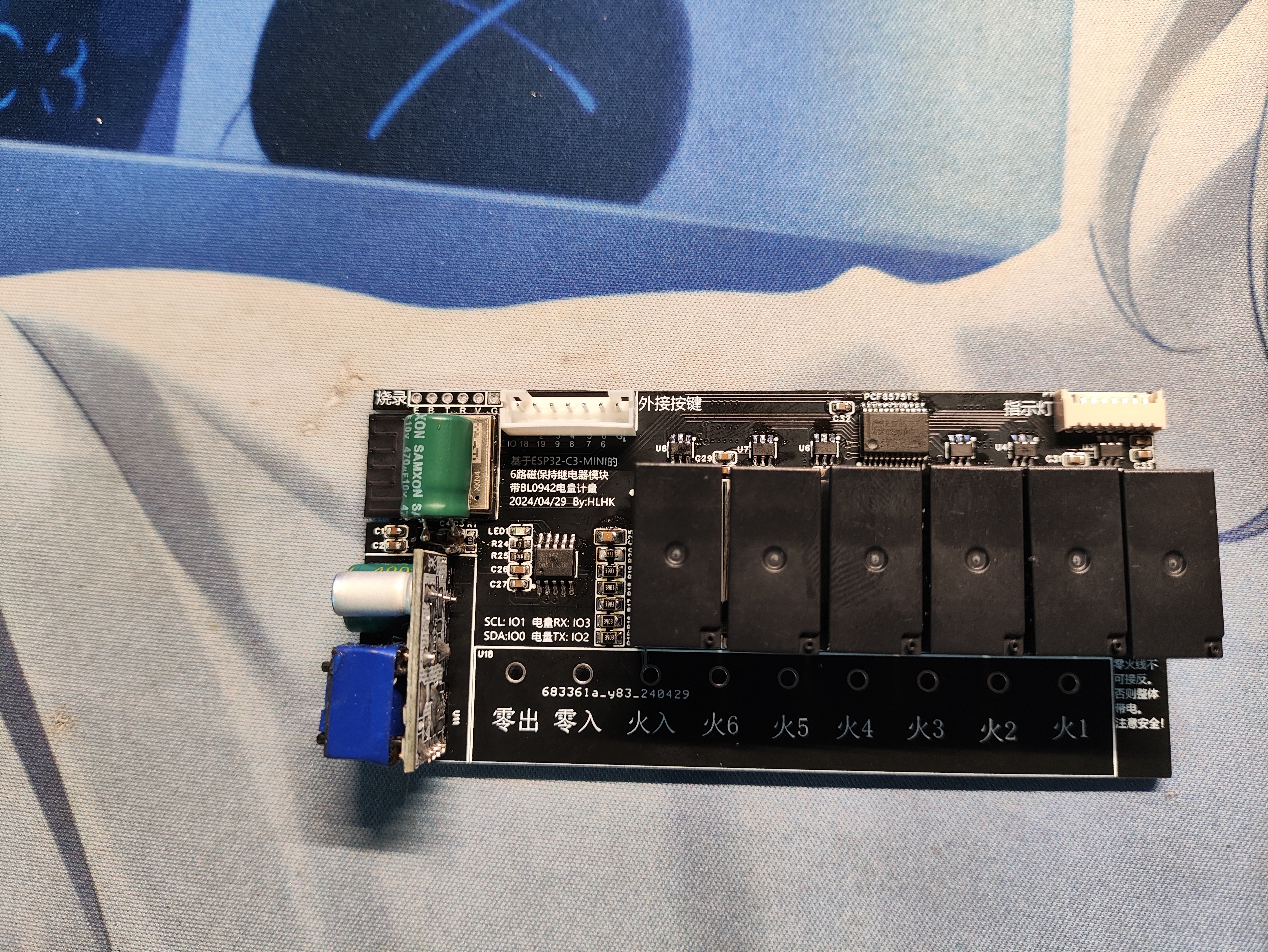
This test used optocoupler feedback to monitor the actual switching state.
ESPHOME is still used as the driver. Next, consider whether to solder the optocoupler feedback circuit on the back.
Currently, the optocoupler feedback uses a simple resistor in series with the optocoupler; with a 200K resistor,
the heat generated by this resistor when all six are on simultaneously will make the PCB warm and produce approximately 1.5W of power. Please consider whether to use this method.
Two ESPHOME configuration files are provided in the attachment: one for when soldering feedback is available, and one for when it is not.
The software assumes a switch state.yml
Optical Coupler Actual Feedback.yml
PDF_6-way metering magnetic latching relay switch-espc3.zip
Altium_6-channel magnetic latching relay switch with metering - espc3.zip
PADS_6-channel magnetic latching relay switch with metering - espc3.zip
BOM_6-channel magnetic latching relay switch with metering - espc3.xlsx
94863
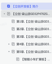
JLCIC Liangshan School - Intelligent Vehicle - Design Learning
Familiar with the development process of embedded projects, and possess the ability to design hardware circuits, program software, and debug systems for intelligent vehicles.
Project Description:
This project is a learning and replication project based on the materials provided with the JLCSC Liangshanpai development board. It replicates the entire process of designing, soldering, and programming an intelligent car. This was a learning experience from scratch. Previously, I had never studied embedded systems before. Although I had taken related courses, I lacked a clear goal and hands-on experience. After completing the course, I didn't know what it was for and quickly forgot it. By chance, I discovered that the JLCSC Liangshanpai development board was available for application. I was very interested in the intelligent four-wheel drive car, which had abundant learning materials and video tutorials. So, I applied for a development board, purchased the relevant components, and after a long period of learning, finally built the car. Seeing my own project successfully running was incredibly rewarding. Many problems were encountered during the design process. This article is a simple record of the process from applying for and purchasing the development board to the completion of the car.
1. Development Board Application:
JLCPCB offers free application for the Liangshanpai development board for students. However, to avoid free access and wasted time, a "pay first, receive coupon later" rule is used. You pay for the development board upfront, and within five months, after learning with the board and designing your own project, the money will be refunded in the form of a coupon. The
purchase link is below. Click "Student Free Application," fill in the relevant information, pay, and then wait for the development board to arrive.
(LCPCB development board, Liangshan Pi, Liangshanpai, STM32 development board, GD32 development board, embedded systems, microcontroller, domestic 32) (lckfb.com)
2. PCB and Components:
Compared to simple learning, I prefer learning by combining hands-on experience. In the Liangshanpai development board materials, I was interested in the intelligent car section, so I first purchased the related components. To manufacture the smart car shown in the image below, you need to purchase a PCB and components. The PCB, the blue board, is a composite board that connects various components together. It contains copper wires and here also acts as the car's body. Components include resistors, capacitors, LEDs, etc., which can be designed to achieve different functions. You can design these yourself, but my goal was to understand the entire embedded development process, so I used a pre-designed project from JLCPCB. The link is as follows: https://oshwhub.com/li-chuang-kai-fa-ban/zhi-nen-xiao-che-kuo-zhan-ban.
After opening the link, you will see the schematic and PCB board shown below. Click "Open in Editor" in the lower right corner to open it using JLCPCB's online EDA.
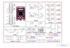
There are several versions available; I chose the second one. There are order options above the project; click to order the PCB and components respectively. Detailed tutorials are available online, so I won't go into detail.
Important Notes: There are a few points to note. PCB printing starts at 5 units, which provides error tolerance but also increases costs. Given the large size of this smart car board, the cost might be 70-80 yuan. Many problems arose during component procurement, especially after soldering, forcing production to stop midway. Components were purchased online. You can buy them from LCSC's online store, or from [other online retailers].
mmexport1715265980171.mp4
PDF_Jialichuang Liangshan School_Intelligent Vehicle_Design Learning.zip
Altium_Jialichuang Liangshan School_Intelligent Vehicle_Design Learning.zip
PADS_Jialichuang Liangshan School_Intelligent Vehicle_Design Learning.zip
BOM_Jialichuang Liangshan School_Intelligent Vehicle_Design Learning.xlsx
94864
electronic


 京公网安备 11010802033920号

 HCP0703-R82-R


