
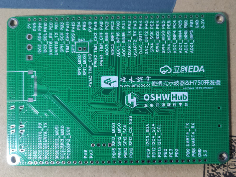
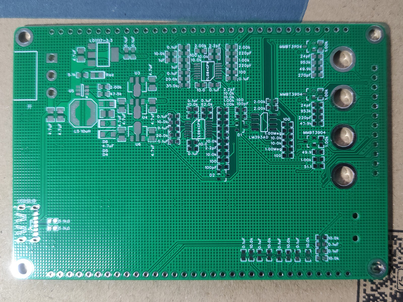
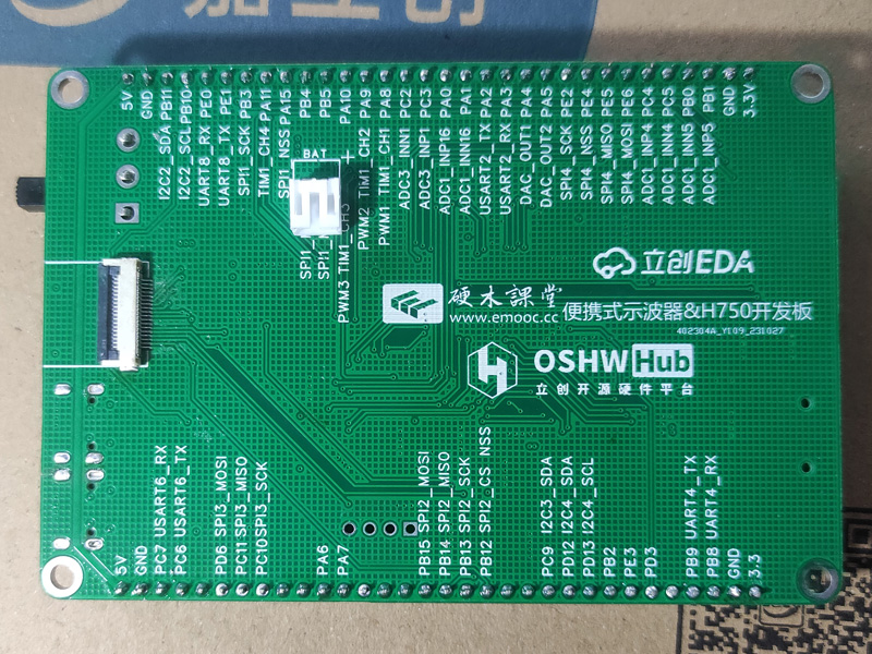
 Oscilloscope expansion board:
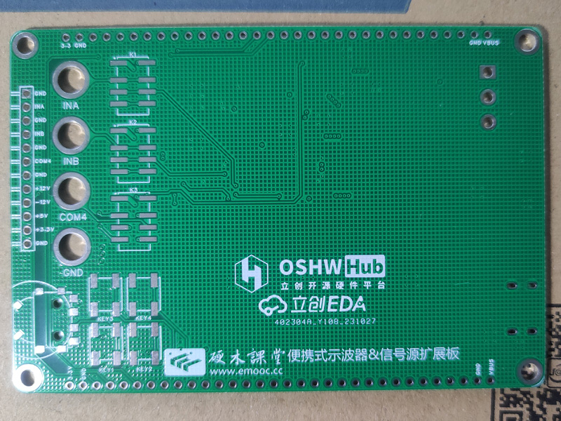
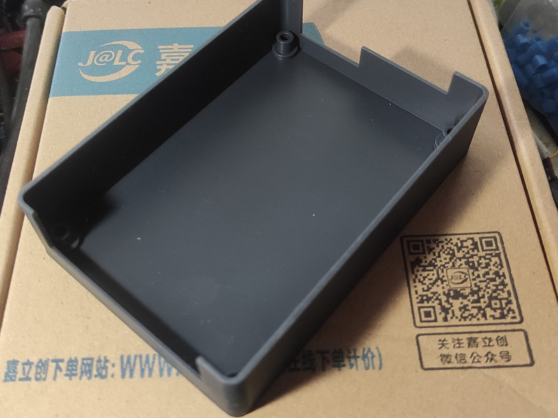
 3D Monkey 3D printed shell photos:

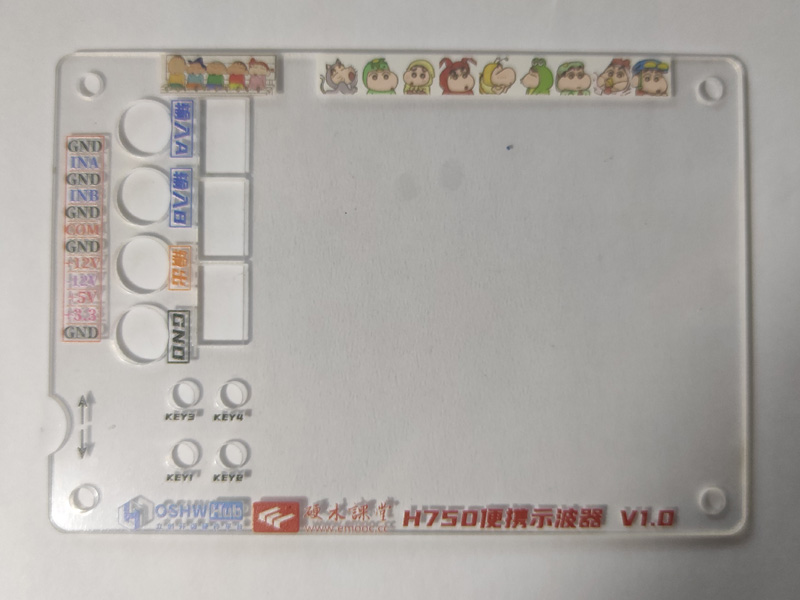
 The panel was exported from a PDF using an editor, converted to an image, and then imported into the panel editor. It was then drawn according to the positions of each component, but the result was too small, so it's just usable. There may have been errors during various conversions and imports; I must pay attention to checking the dimensions next time!
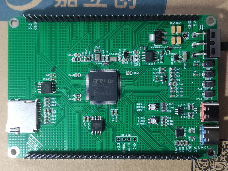

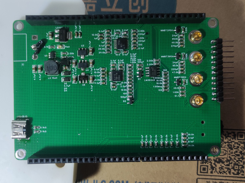 The soldering order for the H750 core board was: first solder the Type-C interface and power supply; after testing the power supply and confirming it was working, then solder the STM32 main unit and peripheral circuits; after testing it again, write the main program; the third step was to solder the LED screen circuit, then test if the screen lit up; after it lit up, solder the other peripheral circuits and pin headers! The test passed completely!


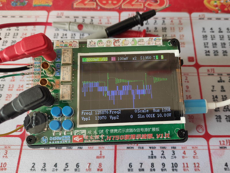
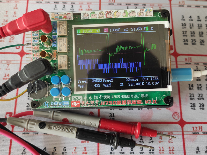
 Since this H750 core board includes a USB interface, flashing the program was relatively simple. Open the STM32CubeProgrammer software, connect the core board to the computer using a Type-C data cable, press and hold the Boot button to power on the core board, adjust the USB connection in STM32CubeProgrammer, and then open the compiled DAC.hex file to download and flash the program.
All reference designs on this site are sourced from major semiconductor manufacturers or collected online for learning and research. The copyright belongs to the semiconductor manufacturer or the original author. If you believe that the reference design of this site infringes upon your relevant rights and interests, please send us a rights notice. As a neutral platform service provider, we will take measures to delete the relevant content in accordance with relevant laws after receiving the relevant notice from the rights holder. Please send relevant notifications to email: bbs_service@eeworld.com.cn.
It is your responsibility to test the circuit yourself and determine its suitability for you. EEWorld will not be liable for direct, indirect, special, incidental, consequential or punitive damages arising from any cause or anything connected to any reference design used.
Supported by EEWorld Datasheet
EEWorld
subscription
account

EEWorld
service
account

Automotive
development
community

Robot
development
community

About Us Customer Service Contact Information Datasheet Sitemap LatestNews


Room 1530, 15th Floor, Building B,
No.18 Zhongguancun Street,
Haidian District,
Beijing, Postal Code: 100190
China
Telephone: 008610 8235 0740
 京公网安备 11010802033920号

 MJHS-01R4-44L-018-2N22


