 : Oscilloscope Menu Explanation: SC, SH, and TR on the right are the control menus. The three middle positions at the bottom display data, and the single letters on either side indicate status.
  On: Press the middle button, PW_ON is pulled low, Q1 conducts, BAT supplies power to the buck chip, the main control chip powers on, the pin connected to PW_CT is pulled high, Q2 conducts, the green light illuminates, and the middle button can be released to complete the power-on process.
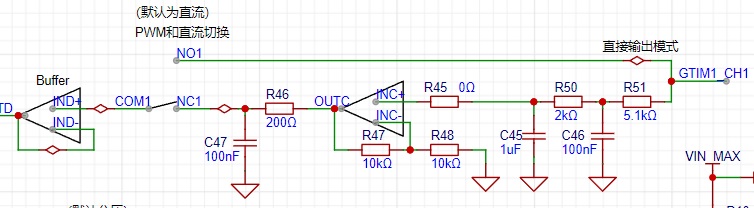 : There will be a voltage drop when the PWM filter is converted to DC. After being amplified by 2 times by the amplifier, the output is 0~+6V, and then after a first-order filter, it is output or directly fed into the comparator.
  The DC output of the comparator circuit serves as the reference voltage for the hysteresis comparator. The inverting terminal is the input voltage, which can be used to measure the frequency of the input signal. Note that the timer must be selected in rising or falling edge mode and the settings must be inverted.
 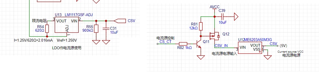 uses an LM1117GSF-ADJ, with a control current of 2mA. R55 is the bleeder resistor for C31. The 17.5V is stepped down to 5V by an LDO and input to the LM1117GSF-ADJ.
  allows communication with a host computer. Bluetooth remote control or mouse/keyboard macro functions may be added later.
 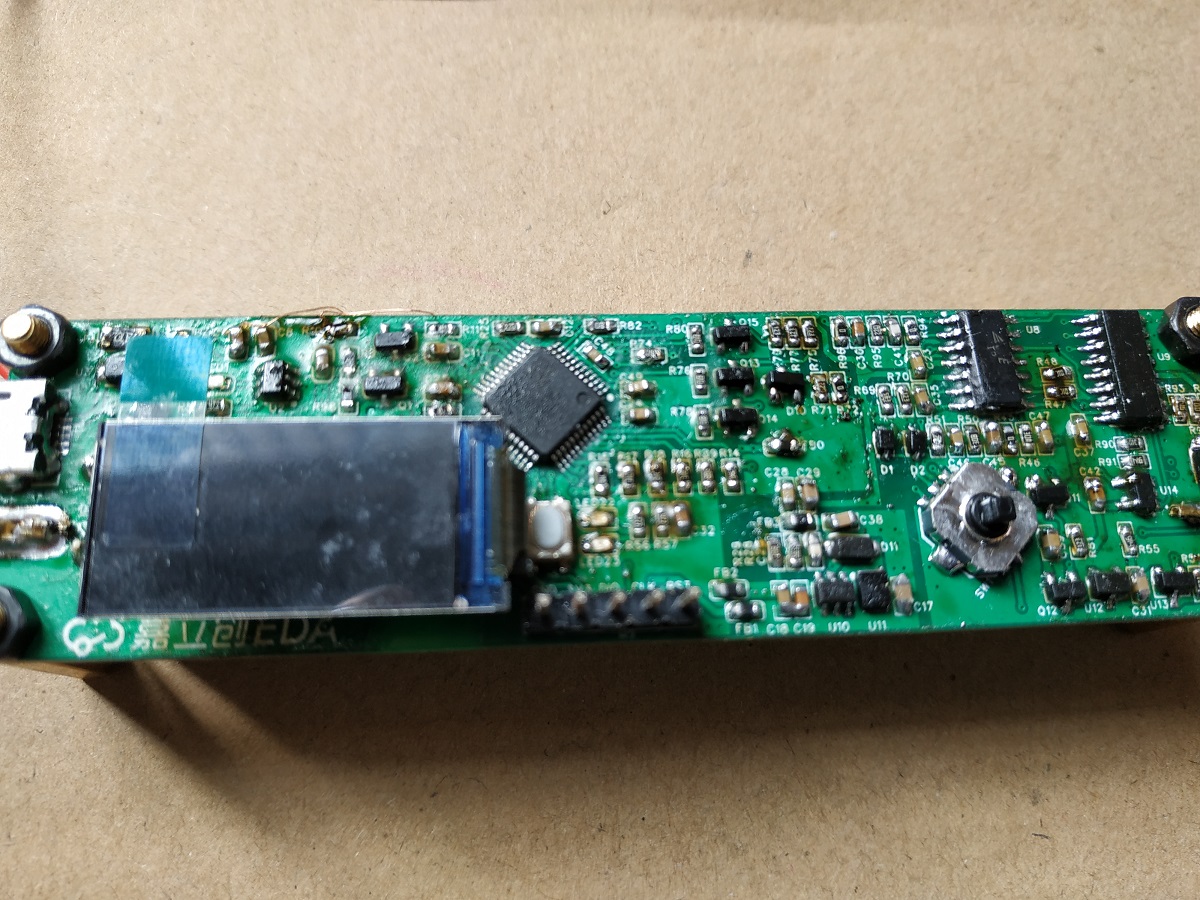 For ease of debugging, the resistor connected to PW_ON is grounded to keep the chip constantly powered.
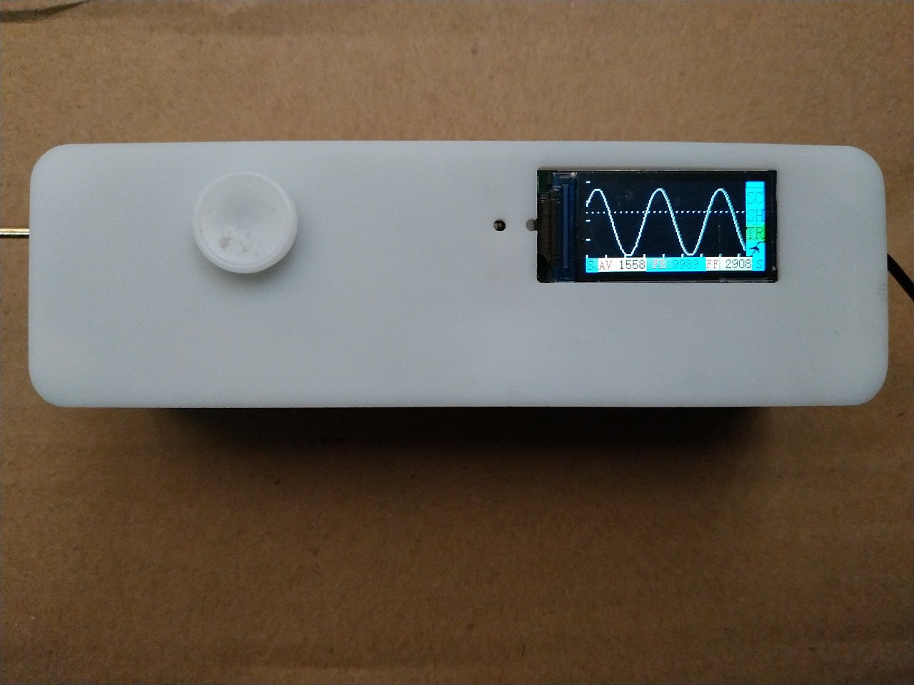
 The PWM output shows spikes on both rising and falling edges; this is still being studied.
 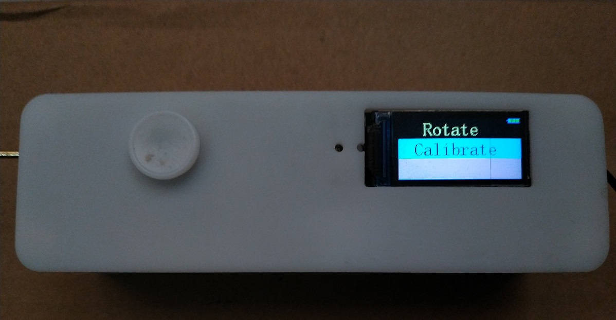 A screen rotation function has been added to facilitate left- or right-handed use.
All reference designs on this site are sourced from major semiconductor manufacturers or collected online for learning and research. The copyright belongs to the semiconductor manufacturer or the original author. If you believe that the reference design of this site infringes upon your relevant rights and interests, please send us a rights notice. As a neutral platform service provider, we will take measures to delete the relevant content in accordance with relevant laws after receiving the relevant notice from the rights holder. Please send relevant notifications to email: bbs_service@eeworld.com.cn.
It is your responsibility to test the circuit yourself and determine its suitability for you. EEWorld will not be liable for direct, indirect, special, incidental, consequential or punitive damages arising from any cause or anything connected to any reference design used.
Supported by EEWorld Datasheet
EEWorld
subscription
account

EEWorld
service
account

Automotive
development
community

Robot
development
community

About Us Customer Service Contact Information Datasheet Sitemap LatestNews


Room 1530, 15th Floor, Building B,
No.18 Zhongguancun Street,
Haidian District,
Beijing, Postal Code: 100190
China
Telephone: 008610 8235 0740
 京公网安备 11010802033920号

 8-147731-3


