Video Link:
[Bilibili Video - Function Demonstration and Introduction](【LCSC Training Camp, Building a Voltage and Current Meter Based on CW32, Adjustable Power Supply in One】 https://www.bilibili.com/video/BV1STWDeCERz/?share_source=copy_web&vd_source=1a525d1b985ccfef0e5f38b4953f8495)
Design Background:
ADC (Analog-to-Digital Converter) is an indispensable key component in electronic systems. It converts continuous analog signals into digital signals, enabling digital processing and analysis. ADCs play a crucial role in signal conversion, measurement and data acquisition, control system input, and communication and signal processing. Their widespread application promotes the intelligent and precise control of electronic equipment in various industries and is one of the key factors driving modern technological progress.
The digital voltage and current meter combines ADC technology with circuit measurement principles, accurately converting analog voltage and current signals into digital displays, facilitating intuitive reading and analysis by electronic engineers. This device not only improves the accuracy and efficiency of circuit measurements but also helps engineers better understand circuit behavior. It is a powerful tool for electronic design and troubleshooting, playing a crucial supporting role in the work of electronic engineers. In product applications, digital voltmeters and ammeters ensure the accuracy and safety of circuit design while also providing strong support for product quality control and subsequent maintenance.
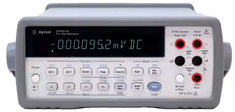
Figure 32 shows a benchtop digital multimeter (Agilent 34401A).
An adjustable regulated power supply is an electronic device or module that provides a stable, adjustable DC power output. Adjustable regulated power supply modules are very common in electronic laboratories and engineering research and development. They can provide a stable, adjustable power supply for electronic components, circuit boards, and experimental equipment. This allows engineers and researchers to adjust the power supply voltage and current as needed to meet the testing, verification, and development requirements of different circuits and devices. Using an adjustable regulated power supply module provides a reliable power supply, facilitating troubleshooting, testing, and verification. It can be used to simulate or replace the power supply section of equipment to verify whether the power supply is working properly.

Learning to design and build a digital voltmeter and ammeter is highly beneficial for improving one's professional skills. This digital voltmeter and ammeter project covers multiple aspects, including microcontroller circuit design and implementation, signal acquisition and processing circuit design, user interface development and optimization, and product appearance design. It integrates knowledge from multiple fields such as electronics, microcontroller programming, circuit design, and industrial design. Considering the learning pace and knowledge absorption capacity of beginners, we have specially launched this introductory-level digital voltmeter and ammeter project, which is very suitable for beginners in electronics and those who want to learn more about microcontroller applications. This project has the following highlights:
it adopts a core board plus expansion board design concept and uses plug-in components, making learning simpler and exploration more in-depth;
the core board uses the domestic Wuhan Xinyuan Semiconductor CW32 as the main controller, while also being compatible with other similar development boards; however, the CW32 has advantages.
The project is highly comprehensive and practical, and after completion, it can be used as a desktop instrument;
the project has abundant learning materials, including circuit design tutorials, PCB design, code programming learning, and training for engineers' debugging skills.
Project Overview:
This project is a combined voltage and current meter and adjustable power supply device based on the LCSC CW32F030C8T6 development board, which can basically meet the desktop debugging needs of electronics enthusiasts. Compared with professional instruments, it has the advantages of convenient learning and low cost. It can be powered by a common DC2.1 switching power supply, with a wide voltage range, supporting up to 30V input.
Project Functions:
This design is a temperature and humidity alarm system based on the LCSC CW32F030C8T6 development board; it features voltage detection, current detection, output voltage of 1.3V-27V, and can provide a 1.2A load capacity (with good heat dissipation). Overcurrent protection thresholds can be set for the output voltage (software implementation), and it displays current or power switching. Project
Parameters
: Voltage detection range: 0-30V;
Current detection range: 0-3A.
It can detect the voltage and current values of the tested circuit in real time;
it can provide external power supply capacity, basically replacing the desktop adjustable power supply.
It displays current or power switching.
Principle Analysis (Hardware Description)
This project consists of the following parts: power supply, LED digital tube display and LED indicator, LCSC CW32F030C8T6 development board (main controller), LM317 for external power supply, and voltage and current detection circuit. This project mainly uses the ADC integrated in the CW32F030C8T6 to receive and process voltage and current signals, calculating the actual operating voltage and current. When supplying external power, if the current exceeds the set protection threshold, the LM317 is shut down, and the output voltage drops to a minimum of approximately 1.25V.

Power Supply Circuit:
LDO (Low Dropout Linear Regulator) Selection
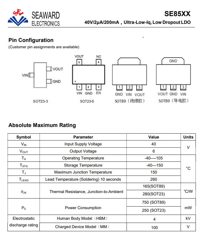
This project uses an LDO as the power supply. Considering that most voltmeter products are used in industrial scenarios with 24V or 36V power supplies, the SE8550K2 with a maximum input voltage of 40V was selected as the power supply. The main reason for not using a DC-DC buck converter to handle the large voltage drop is to avoid introducing DC-DC ripple interference during the design process; a secondary reason is to reduce project costs. From the table in the datasheet screenshot, it can be seen that the SOT89 package (165℃/W) offers better thermal resistance (Junction-to-Ambient) compared to the SOT23 package (280℃/W). For the LDO model selection
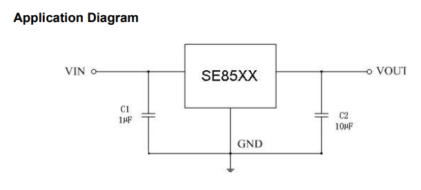
, since the project's main control board is powered by 5V, the SE8550K1-HF is selected based on the ordering information in the table below. It outputs 5V, and K indicates the SOT89 package, offering better ±1% accuracy. HF or LF is related to environmental requirements and needs to be considered in actual product design. This is not a concern for this project. The capacitor design manual provides an application schematic for this LDO: almost all LDO devices operate on essentially the same principle in circuit design. Therefore, this schematic is not very useful for reference. The key consideration is often how C1 and C2 should be designed. If your LDO has an EN (enable) pin, you also need to consider the design of the enable pin to ensure the chip functions properly. In addition, some LDOs have adjustable outputs, which have a dedicated pin (adj) that requires the configuration of corresponding external resistors to achieve the specified output voltage. The most crucial aspect of LDO peripheral circuit design is the capacitor design. The capacitors surrounding the LDO play a critical role in the circuit, primarily in the following ways: Filtering: The capacitors surrounding the LDO, especially the input capacitor, can effectively filter out ripple interference from the preceding power supply. Improving load transient response: The output capacitor plays a vital role in improving load transient response. When the load current changes drastically, the LDO has an adjustment time. During this time, the output capacitor acts as a temporary power supply, providing the necessary current to the circuit and preventing the output voltage from being pulled too low. A larger output capacitor value can further improve the LDO's transient response to large load current changes.

Phase Compensation: For adjustable output LDOs, the capacitor connected in parallel with the upper resistor (R1) (called the feedback capacitor CFB) provides leading phase compensation, increasing oscillation margin and improving load transient response. Zeroing both CFB and R1 contributes to loop stability.
Oscillation Prevention: Proper capacitor configuration helps prevent oscillations in the LDO circuit, ensuring stable circuit operation.
Ripple Suppression: Capacitors in LDOs also help improve the power supply rejection ratio (PSRR), reducing the impact of power supply noise on circuit performance.
Startup Inrush Current Control: The input capacitor acts as a temporary power source for startup inrush current during LDO startup, preventing the input voltage from being pulled low and affecting the stability of the preceding power supply.
Summary: The capacitors surrounding the LDO play a crucial role in filtering, improving load transient response, phase compensation, oscillation prevention, ripple suppression, and startup inrush current control. Proper configuration of these capacitors ensures the stability and performance of the LDO circuit.
If you carefully review the datasheet, you'll find detailed suggestions and references, as well as layout design recommendations. This avoids engineers performing extensive theoretical calculations.
It's worth noting that in my power supply design, I used electrolytic capacitors and ceramic capacitors connected in parallel, one after the other. When electrolytic and ceramic capacitors are connected in parallel, they complement each other, providing good filtering in both high and low frequency ranges. The electrolytic capacitors filter out low-frequency interference, while the ceramic capacitors filter out high-frequency interference; their combination achieves better filtering.
In practical electronic products, the main function of electrolytic capacitors connected in parallel with ceramic capacitors is to achieve high and low frequency filtering and coupling through their complementary characteristics, thereby improving circuit performance, stability, and anti-interference capabilities. This parallel connection method is widely used in electronic devices.
When electrolytic and ceramic capacitors are used in parallel, the electrolytic capacitors first filter out the low-frequency portion of the input voltage, providing a stable DC voltage for the circuit. This helps ensure the stability and reliability of the circuit at low frequencies.
Subsequently, the ceramic capacitors further compensate for high-frequency fluctuations, filtering out high-frequency noise and pulse hazards. This high-low pairing filtering method can more effectively filter out noise and fluctuations across the entire frequency band, improving the overall performance of the circuit.
Furthermore, ceramic capacitors can eliminate the inductive characteristics (parasitic inductance of capacitors) generated by electrolytic capacitors at high frequencies, further improving the filtering effect.
When beginners try to understand the functions of capacitors such as DC blocking, coupling, bypassing, filtering, tuning circuits, energy conversion, and control, they should first return to basics and understand the essence of capacitors: capacitors are used to store charge and electrical energy and can release these stored charges in the circuit.
To briefly explain why capacitors around the MCU should be placed nearby: distant solutions are ineffective. When MCUs and other devices are using electricity, the current value on the line may change abruptly. Sometimes, to maintain the demand for abrupt current on the MCU (i.e., the physical quantity formed by the directional movement of charge), a nearby capacitor is needed to release charge.
The magnitude of the current reflects the amount of charge passing through the cross-section of a conductor per unit time, an important physical quantity describing the state of charge movement in the circuit. To
prevent reverse connection
, considering that high-voltage reverse connection can cause irreversible damage to the module, the voltmeter power supply circuit uses a series diode scheme for reverse connection protection.
Note: This project uses series diodes for reverse connection protection because the power supply voltage of this equipment is usually higher than 5V. The 0.7V voltage drop of the diode will not affect the power supply. When the power supply voltage is low, the overall power consumption of the project is low, and the measured power supply current is low (20mA). Due to the unique structure of the Schottky diode D4 (1N5819), its VF is lower than that of general switching diodes, as shown in the figure below, with a voltage drop of approximately 0.2V or less.
In conventional circuit design, the reverse connection protection and circuit protection can also be achieved by using a reverse parallel diode + series fuse.
Diode voltage-current curve
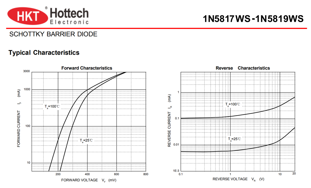
. The role of the series small resistor (10Ω):
This project additionally uses a series small resistor (10Ω) for voltage division. On the one hand, it reduces the problem of severe heat generation of the LDO due to the large voltage difference under high voltage conditions. On the other hand, it utilizes the principle that the series 10-ohm low-power resistor has low overcurrent, acting as a low-resistance fuse, providing overcurrent protection or short-circuit protection. (The point where the resistor acts as a fuse is that, because the resistor is in an overcurrent state and heating state, it is 99% open circuit, and it will basically not short circuit. Its fault analysis determines that it is basically open circuit. That is, it burns out and will not short together.)
The small series resistor (10Ω) can also reduce the peak value of the power-on surge and avoid damage to the LDO
due to excessive surge. If electrolytic capacitors are not used, the small series resistor (10Ω) can also prevent the conductor inductance and ceramic capacitor from resonating during hot plugging and unplugging. Because ceramic capacitors have very low ESR, the damping in the LC network is very small, and the gain at the resonant point will be very high. Adding an external resistor to provide damping can suppress the gain at the resonant point.
Circuit design points and specifications for
grounding: Single-point grounding. The ground of the current power supply is connected to the GND of the main electrolytic capacitor of the current power supply. The main electrolytic capacitors of each stage of the power supply are connected to the GND of the main electrolytic capacitor of the previous stage power supply.
Single-point grounding in PCB design means that there is only one point on the PCB board connected to the ground of the entire system. This means that all circuit ground wires will be connected to this common grounding point to form a unified grounding system. Single-point grounding in PCB design is an important circuit design technique. Its main purpose is to simplify circuit design and improve system stability and anti-interference capabilities.
Benefits of single-point grounding include:
Simplified circuit design: Single-point grounding can greatly simplify circuit design, reduce the length and complexity of connection lines, and reduce the possibility of electromagnetic interference.
Improved system stability: Single-point grounding allows for better control of the ground loop size, reducing the impact of ground loops on signal transmission and system stability, thereby improving system stability and reliability.
Reduced noise and interference: Single-point grounding reduces the return path of signals and current, reducing return noise generated in the system and improving the quality and reliability of signal transmission.
Reduced ground loop generation: Single-point grounding effectively reduces the generation of ground loops, avoiding nonlinear effects of ground loops and reducing interference and noise generated in the system.
In PCB design, single-point grounding can be implemented in the following ways:
Series single-point grounding: Connecting all points requiring grounding in series with a common ground wire and then connecting them to a common grounding point. This method is simple and easy to implement, but a long ground wire may introduce significant impedance.
Parallel single-point grounding: Connecting each point requiring grounding directly to a common grounding point with a short ground wire. This method can reduce ground impedance, but may require more grounding points and more complex wiring.
Hybrid grounding: Group circuits according to signal characteristics. Circuits that do not interfere with each other are placed in one group. Circuits within the same group use series single-point grounding, while circuits in different groups use parallel single-point grounding. This method can flexibly meet the needs of different circuits and improve the overall system performance.
Precautions:
Choose a suitable grounding point: The grounding point should be chosen at the point on the circuit board with the most stable potential, usually near the negative terminal of the power supply filter capacitor.
Control ground wire length: The ground wire length should be as short as possible to reduce ground impedance and introduced noise.
Avoid ground loops: During the design process, ground loops should be avoided as much as possible to reduce the noise and interference generated by ground loops.
Separate processing of digital and analog signals: Due to the rapid changes in digital signals, noise is easily generated on digital ground. Therefore, analog ground and digital ground should be processed separately as much as possible to reduce interference between them.
In summary, single-point grounding in PCB design is an important circuit design technique that can improve the overall performance of the circuit by simplifying circuit design, improving system stability, and reducing noise interference. In practical applications, it is necessary to select an appropriate single-point grounding implementation method based on specific system requirements and performance requirements, and pay attention to controlling the ground wire length, avoiding ground loops, and separating digital and analog signals.
This project uses the LCSC CW32F030C8T6 development board (core board) as the main controller.
The correct selection of the main controller device is very important, as it relates to the overall advantage of the project.
Regarding the voltmeter and ammeter, the author conducted some debugging and testing using STM32/CW32 and some other 32-bit microcontrollers. Here, only a comparison with STM32F103C8T6 is made as a reference for learning device selection, mainly to provide ideas and improve understanding.
Avoid blindly selecting
an MCU (Microcontroller Unit). When selecting an MCU for this project, multiple aspects need to be considered to ensure that the chosen MCU meets the project requirements.
Clearly define your project needs: Understand the required computing power, including clock speed, processor core type, and whether a floating-point unit is needed.
Identify the required I/O ports and important peripherals, such as ADC peripherals. Since this is a development board project, primarily for debugging and learning, there are no strict limitations on the number of I/O ports; i.e., the associated costs are not considered.
Key advantages of CW32 in this project
: Wide operating temperature range: -40~105℃;
Wide operating voltage range: 1.65V~5.5V (STM32 only supports 3.3V systems);
Strong anti-interference: HBM ESD 8KV; All ESD reliability reaches the highest international standard level (STM32 ESD 2KV);
Project focus - Better ADC: 12-bit high-speed ADC, achieving ±1.0LSB INL 11.3ENOB; Multiple Vref reference voltages... (STM32 only supports VDD=Vref);
Stable and reliable eFLASH technology. (Flash0 pending).
A detailed explanation of these advantages will be provided in the ADC sampling section and extended sections.
Key features of CW32's ADC:
This project requires a focus on 4 reference voltage sources. Content from the "CW32x030 User Manual".

3. Voltage Sampling Circuit :
This project uses a voltage divider circuit to achieve high voltage acquisition, designed to acquire voltages up to 100V; the current configuration acquires voltages from 0-30V.
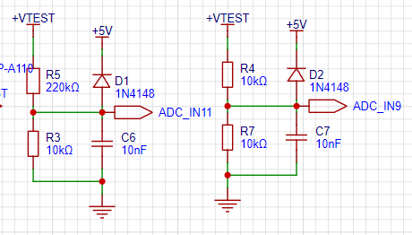
Figure 5
shows that the voltage divider resistors in this project are 200K+10K, so the voltage division ratio is 20:1 (ADC_IN11).
The voltage divider resistor selection
is based on the maximum measured voltage. For safety reasons, this project uses 30V (the actual maximum can be 99.9V or 100V).
The ADC reference voltage in this project is 1.5V, which can be configured through the program.
To reduce the power consumption of the sampling circuit, the low-side resistor (R7) is usually selected as 10K based on experience.
Then, the high-side resistance of the voltage divider resistor can be calculated using the above parameters. The
required voltage division ratio is calculated as follows: ADC reference voltage: Design input voltage, which can be calculated using known parameters as 1.5V/30V=0.05.
The high-side resistance is calculated as: Low-side resistance/voltage division ratio, which can be calculated using known parameters as 10K/0.05=200K.
A standard resistor is selected: A resistor slightly higher than the calculated value is chosen. The calculated value is 200K. We usually choose E24 series resistors, so in this project, we choose 200K, which is greater than 200K and closest to it.
If, in actual use, the voltage to be measured is lower than 2/3 of the module's design voltage (66V), the voltage divider resistor can be replaced and the program modified to improve measurement accuracy. The following example illustrates this:
Assuming the measured voltage is no higher than 24V and other parameters remain unchanged,
calculations show 1.5V/24V = 0.0625, 10K/0.0625 = 160K. 160K is a standard E24 resistor and can be directly selected, or a higher value 180K can be chosen with some redundancy.
If, in actual use, the voltage to be measured is higher than the module's 99V design voltage, a different resistor can be selected. To expand the voltage measurement range, you can choose to replace the voltage divider resistor or modify the reference voltage. Here's a case study:
Assuming the measured voltage is 160V, we can choose to increase the voltage reference to expand the range.
Given that the voltage division ratio of the selected resistor is 0.0145, we can calculate 160V * 0.0145 = 2.32V using the formula. Therefore, we can choose a 2.5V voltage reference to expand the range (increasing the range will reduce accuracy).
Considering the potential fluctuations in the measured power supply, a 10nF filter capacitor is connected in parallel with the low-side voltage divider resistor to improve measurement stability.
Diode clamping ensures MCU safety
. In designing this project, I added an additional 1N4148 (D1, etc.) as a clamping diode to the sampling circuit. This helps avoid damage to the chip pins due to incorrect voltage input during learning and debugging. Diode clamping is an important electronic circuit design technique; its main function is to protect the circuit by limiting the voltage amplitude, preventing damage or malfunction caused by excessively large or small signals.
In circuit design, clamping refers to limiting voltage. Diode clamping specifically refers to the technique of using a diode to limit the potential at a point in a circuit.
Diode clamping primarily utilizes the unidirectional conductivity of a diode. When the voltage across the positive terminal of the diode is greater than the voltage across the negative terminal and the diode is turned on, the voltage across the diode is limited to its voltage drop across the diode, typically around 0.7V for a silicon diode.
The clamping process involves forcibly pulling the clamped potential towards the reference terminal through the diode's clamping action, thus limiting the potential. Clamping does not change the waveform of the original signal; it only raises or lowers the reference potential.
Depending on the diode connection method, clamping circuits can be divided into positive clamping circuits and negative clamping circuits. This project only designs positive clamping.
Positive clamping circuit: When the positive terminal of the diode is grounded, it is a positive clamping circuit. During the positive half-cycle, the diode is cut off; during the negative half-cycle, the diode is turned on, and the capacitor is charged to a certain voltage, limiting the output voltage within a certain range.
Negative clamping circuit: When the negative terminal of the diode is grounded, it is a negative clamping circuit. The working principle is the opposite of the positive clamping circuit.
Adding a voltage sampling circuit enables range
switching.
In this project, an additional voltage sampling circuit was added; therefore, we can discuss the significance of range switching in improving measurement accuracy. To achieve more accurate measurements, multimeters are often set with multiple ranges. By adjusting different ranges, the optimal measurement accuracy of the measured point within the corresponding range can be obtained.
This project requires a combination of hardware and software to achieve this function. When we first use the ADC_IN11 channel mentioned earlier to measure voltages within 30V, if the measured voltage is within 0~3V, then we use the ADC_IN9 channel for measurement. At this time, due to the reduced voltage division ratio, the measurement accuracy is greatly improved.
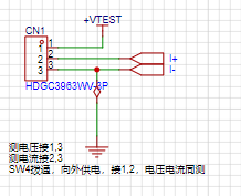
There are many ways to implement range switching, and the development board design provides more design possibilities. Figure 6 shows the circuit diagram
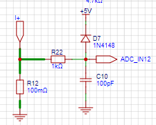
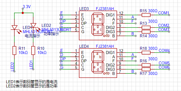
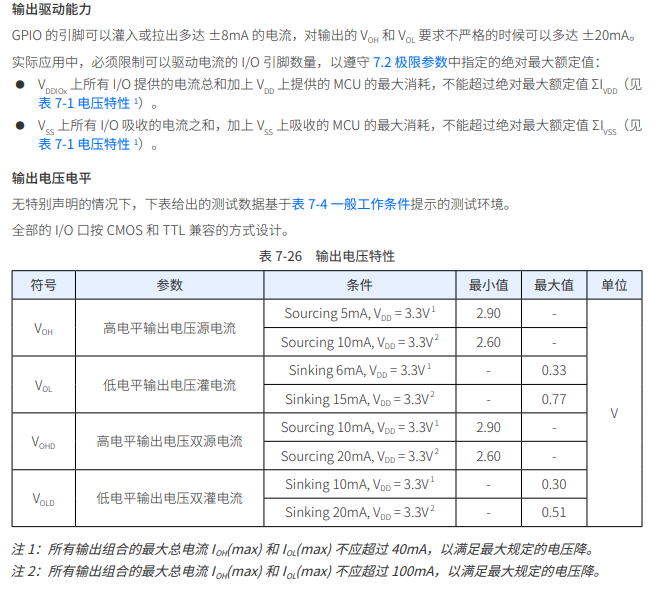
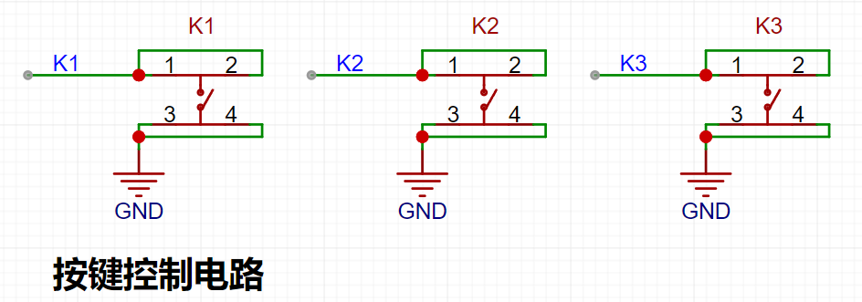
used for simulating voltage measurement, calibration, and measurement calibration assistance. Figure 7 shows the circuit diagram used for simulating voltage measurement, calibration, and measurement calibration assistance. The devices labeled T_V and T_GND next to the voltage measurement terminals are the 2mm banana plug interfaces on the development board, used to connect multimeter probes. Multimeter or high-precision benchtop digital multimeter probes can be inserted to verify the accuracy of the development board's measurements. Alternatively, 2mm banana plug multimeter probes can be inserted to replace the CH1 port for handheld measurements. The VP pin is the power supply pin for the development board and should not be connected when using the DC port. When not using DC port power and the measured value is greater than 5V and less than 30V, the power supply under test can be connected, or it can be powered independently. Considering that users may not be able to easily build external circuits for testing and debugging when learning the corresponding circuit measurement principles, and adhering to the principle of ease of development of the development board, auxiliary circuits for simulating voltage measurement, measurement calibration, and measurement calibration are specially set up. No external voltage is required for CH1. Use the multi-turn adjustable potentiometer (RP1) to divide the power supply voltage of the development board and connect it to the +V network through the internal circuit of the development board. Note that JP1 needs to be shorted at this time; a jumper cap is sufficient, and a long-handled jumper cap is recommended. Do not short JP1 if this function is not used. Current Sampling Circuit: This project uses a low-side current sampling circuit for current detection. When learning the low-side of the sampling circuit and the development board meter interface , do not solder R0!!! Figure 8 Design Analysis: The sampling current designed for this project is 3A, and the selected sampling resistor (R0) is 100mΩ. The following aspects need to be considered when selecting the sampling resistor: the maximum value of the pre-designed measurement current; the voltage difference caused by the 3A current sensing resistor in this project ; generally, it is not recommended to exceed 0.5V ; the power consumption of the current sensing resistor should be selected based on this parameter; considering the power consumption (temperature) issue under high current , a 1W packaged metal wire-wound resistor was selected ; the voltage amplification factor of the current sensing resistor: no operational amplifier was used to build the amplification circuit in this project, so the factor is 1. The current sensing resistor value can then be calculated using the above parameters. The project does not use an amplifier circuit, therefore a larger sampling resistor is needed to obtain a higher measured voltage for measurement. Considering that a larger resistor would result in a larger voltage drop and higher power consumption, an unlimited selection of a larger resistor is not feasible . This project uses a 1W package resistor, corresponding to a power rise of 1W. Based on the above data, a 100mΩ current sensing resistor was chosen. According to the formula, 3A * 100mΩ = 300mV, 900mW. To handle different operating environments, especially high-current scenarios, the R0 resistor can be replaced with constantan wire or a shunt. The choice of alternative can be based on the specific application scenario. For safety and educational purposes, this project will not discuss measurements exceeding 3A, but the principle remains the same. Protecting the ADC pins: Connecting a resistor in series before the ADC pins can limit current and prevent damage to the ADC pins due to excessive current under special conditions (such as high voltage input or short circuit). It also reduces the impact of transient current on the ADC converter performance. Filtering and Noise Reduction: The resistors and capacitors at the back end of the ADC pins can form an RC low-pass filter, which helps to slow down the fast edges of the signal and reduce the impact of high-frequency noise on ADC sampling. In high-precision applications, this filtering effect is crucial for improving the signal-to-noise ratio (SNR) and ensuring measurement accuracy. This project uses two 0.28-inch three-digit common-cathode LED displays as display devices. Compared to displays, LED displays have better visibility in complex environments. Depending on the actual usage environment, smaller current-limiting resistors can be used to achieve higher brightness. Furthermore, LED displays have better mechanical properties and are not as easily damaged by external forces as displays. They are commonly used in industrial applications requiring stability and reliability. From a development board learning perspective, this makes it easier to learn electronic measurement principles and related development in a targeted manner. LED Display and Indicator Circuit for Current-Limiting Resistors of the LED Display: In this project, after actual testing, the current-limiting resistors (R1~R6) of the LED displays were configured to 240Ω. The corresponding brightness, whether for common-cathode or common-anode LED displays, has good visibility and is soft and not glaring. Strictly speaking, the current-limiting resistor should be added to the segment; adding it to the digit would affect the display effect. In our actual design, we added it to the digit to save a few resistors, but the impact on the display is not significant. Therefore, we added it to the digit for convenience. Let's calculate the required current for the digital tube . This project actually uses dynamic scanning to drive the digital tube, so at any given time, only a maximum of 8 segments (or LEDs) are lit, or in other words, only one digit is lit. According to the design, the required driving current is approximately 11mA (IO port high-level voltage 3.3V ÷ 300Ω). At this point, it's important to ensure that the selected MCU has sufficient current-pull/sinking capability. Figures 14 and 15 show that the CW32 has no problem (some chips are not suitable). The selection of the current-limiting resistor for the digital tube display can be found in the datasheet of the digital tube used on the LCSC website; generally, the parameters of similar digital tubes are roughly similar. Figure 16 shows that, according to the datasheet, the current-limiting resistor limits the maximum current to no more than 35mA DC forward current, and the driving voltage is greater than 2.9V (current 20mA). We use a 300Ω current-limiting resistor to reduce the current draw (If) to 11mA. Since the CW32 and its core board can use a 5V system, the current draw would be 16mA. 300Ω is sufficient to ensure normal display; a smaller resistor would result in brighter light. Due to reduced current consumption, the LDO at the power supply terminal can also accept a lower input voltage. Four RGB LEDs are distributed around the perimeter of the board. Different display effects can be achieved by changing the brightness of different colors. Considering the different current requirements of the red, blue, and green LEDs, different resistors are used in series on their respective branches. The brightness can be uniformly adjusted later. Each color LED is connected in series and controlled by a SI2302N channel MOSFET for unified switching on and off. Brightness can also be adjusted by controlling the on-time using PWM. The button control circuit can be designed in various ways. Thanks to the CW32's internal I/O ports which can be configured with pull-up and pull-down resistors, the external button control circuit does not require configuration. One end of the button is connected to the MCU's I/O, and the other end is grounded. When a button is pressed, the I/O pin is pulled low. This is a TL431 circuit design for voltage measurement calibration.


This project adds an extra TL431 circuit to provide a 2.5V reference voltage, which can be used to provide an external voltage reference for the chip to calibrate the AD converter. From a product design perspective, due to the inherent ADC performance advantages of the CW32, this circuit is unnecessary. This circuit was designed on the development board to learn the relevant application principles.
Figure 21
shows the TL431 in a SOT-3 package from a partner semiconductor company. Since its manual is in English, a Chinese manual for the TL431 from TI was provided for easier learning and understanding.
The TL431 is a relatively "old" device, a classic, and widely used, still found in many electronic products.
TI defines it as a "precision programmable reference." On the first page of the references, we can focus on several key characteristics.
Precision: Precision indicates that its output voltage is very accurate. I used a TL431 with ±0.5% accuracy, which measured 2.495V on the board at room temperature. Compared to common Zener diodes, the accuracy is vastly different. In the application circuit diagram, the TL431 is represented by a Zener diode symbol. Adjustable output voltage: The adjustable output voltage is between Vref and 36V. In our project, we use the output Vref voltage. Vref is approximately 2.5V. Therefore, we use 2.5V in the description, which is approximately equal to Vref. Sinking current capability: This refers to how much current the output voltage pin can provide. This is greatly related to the resistance value (R13) in the application circuit. It should not be less than 1mA. If there is no need for sinking current, do not design the current too high, causing unnecessary power consumption.
Figure 22 shows
the TL431 operating principle
. The functional block diagram can be found in TI's datasheet; we only need to analyze its equivalent schematic.
The core of the 431 is an operational amplifier, which acts as a comparator in the circuit. The chip has an internal Vref voltage (approximately 2.5V), which acts on the inverting input of the comparator. A voltage is input to the non-inverting input of the comparator to REF. When this voltage is greater than Vref, the comparator outputs a high level, enabling the transistor and connecting the CATHODE (cathode) and ANODE (anode) terminals. If REF and CATHODE are at the same potential (connected together), the potential at REF is pulled low. When the potential at REF drops below Vref, the comparator outputs a low level, the transistor turns off, and the potential at REF rises back up. When it rises above Vref, the above process continues, repeating the cycle. Because the hardware response speed is extremely fast, the voltage at REF is almost equal to Vref.
Note: The potential at ANODE can be understood as GND 0V.
Figure 23
shows the selection of resistor R13 .
In this project, how was the value of resistor R13, 1K, determined?
In this project, REF needs to output a reference voltage of approximately 2.5V to the MCU's ADC pin. Since the MCU's ADC typically has high internal impedance, there is no sinking current requirement for the REF pin. The sinking current setting should be reduced, but not less than 1mA. Taking 1mA as an example:
According to Kirchhoff's Current Law, the current through REF is negligible, so all the current flows through the TL431.
According to Ohm's Law: R13 = (5V - 2.5V) ÷ 1mA = 2.5KΩ.
In actual projects, a 1kΩ resistor is used to reduce the number of resistor parts used. The sink current is set to: I = 2.5mA.
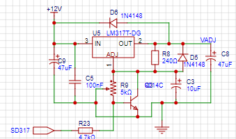
Can R13 be chosen to be even smaller? Yes, but it is not recommended, because unnecessary current flowing into the TL431 will cause the device to overheat and have adverse effects. The LM317
circuit
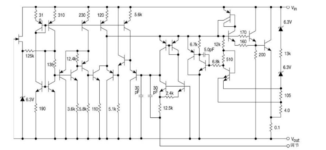
is an adjustable 3-terminal positive voltage regulator, and its working principle is based on a series voltage regulator circuit. The output voltage is adjusted by adjusting the conduction level or equivalent resistance of the internal switching transistor. The LM317 generates a lot of heat during operation because its internal switching transistor has limited output current. To output a larger current, an external power transistor is needed for expansion. The LM317 has an output voltage range of 1.25V-37V and a maximum output current of 1.5A. It incorporates overcurrent and overtemperature protection.
The LM317 is one of the most widely used power supply integrated circuits. It not only features the simplest form of a fixed three-terminal regulator but also offers adjustable output voltage. Furthermore, it boasts a wide voltage regulation range, good voltage regulation performance, low noise, and high ripple rejection ratio. The LM317 is an adjustable three-terminal positive voltage regulator that can provide over 1.5A of current from 1.2V to 37V. This regulator is very easy to use.
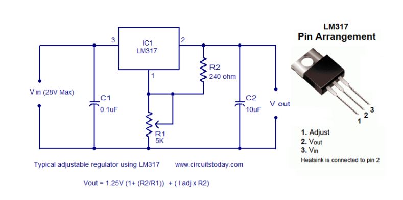
The LM317 is suitable for various applications, including local and card-type regulation. This device can also be used to create programmable output regulators, or, by connecting a fixed resistor between the regulation and output, the LM317 can be used as a precision current regulator. The LM317 regulator circuit operates based on the principle of feedback circuitry, controlling the input voltage by adjusting the output voltage to achieve a stable output voltage. The following is a typical positive voltage regulator circuit using the LM317:
As shown above, this is a classic regulator circuit using the LM317. The input voltage is fed into pin 3 (Vin) of the IC, and the stable output voltage can be obtained from pin 2 (Vout) of the IC. The resistor network consists of R1 and R2, connected to pin 1 (adj), used to set the output voltage. C1 is the input filter capacitor, and C2 is the output filter capacitor. The output voltage of the regulator circuit depends on the formula, Vout = 1.25V(1 + (R2/R1)) + IadjR2. The circuit principle of the LM317 mainly includes the following aspects: Basic working principle: The LM317 adjusts the output voltage by adjusting the conduction level or equivalent resistance of the internal switching transistor. This adjustment is achieved by the voltage difference formed between the output and adjustment pins. You can use two resistors connected between the output and input pins to change the output voltage. In addition, two decoupling capacitors can be connected to a circuit. This integration can eliminate unnecessary coupling and prevent noise. A 1µF capacitor connected to the output improves transient response. It can then be used as a variable regulator by clicking the potentiometer on the adjustable pin. The resistor and potentiometer work together to create a potential difference that regulates the output. Current limiting function: The LM317 regulator has an "adjustment terminal," or "ADJ terminal," which enables current limiting by connecting a resistor R1 and a potentiometer R2 in series between the regulator's output and adjustment terminal. This design allows control of the output current by adjusting the potentiometer, protecting the circuit from overcurrent damage. Application examples: The LM317 is widely used in various power supply circuits, including but not limited to adaptive adjustable power supplies, 0~±30V, 1.5A power supply circuits, and electronic transformer-regulated power supply circuits. These applications demonstrate the versatility and flexibility of the LM317 in providing stable voltage output. In summary, the LM317 circuit principle is based on a series regulator circuit, achieving stable voltage output through the adjustment of the internal switching transistor, and using external components to achieve current expansion and current limiting functions. These characteristics make the LM317 an indispensable power management component in electronic devices. The following is the schematic diagram used in this project , with the transistor base connected to a current-limiting resistor. This allows the microcontroller's I/O port to control the enable and pull-down of the output when excessive current is detected in the external power supply circuit. This LM317 circuit cannot output 0V; the minimum output voltage is 1.25V. ... Project Highlight 1. Mixed use of AH and BH digital tubes:
There are two types of digital tubes: common cathode and common anode. Their pin arrangements are the same, only the cathode and anode are swapped. Since I already have two digital tubes, one common cathode and one common anode, this problem arose. This is a good opportunity to verify and learn whether the two types of digital tubes can be used interchangeably. As we
learned in the previous section on digital tube display principles, only two steps are needed to display:
1. Pull high the anode of the LED inside the digital tube;
2. Pull low the cathode
. Therefore, modifying the AH and BH settings to mix them only requires reversing these two steps.
void Seg_Dis(uint8_t Pos,uint8_t Num)
{
int i;
uint8_t Dis_Value;
// Dis_Value = Seg_Table[Num];
Dis_Value = Seg_Table2[Num];
if (Pos>2) {
Dis_Value = ~Dis_Value;
}
GPIO_LowByte_Write(CW_GPIOA,Dis_Value); //PA02,A
Here we use GPIO_LowByte_Write(CW_GPIOA,Dis_Value); to output the 8 IOs corresponding to the segment at once, which can complete the operation IO quickly, efficiently, and concisely.
void Close_Com(void)
{
GPIO_WritePin(CW_GPIOA,GPIO_PIN_8,GPIO_Pin_SET); //COM1:PA08
GPIO_WritePin(CW_GPIOA,GPIO_PIN_11,GPIO_Pin_SET); //COM2:PA11
GPIO_WritePin(CW_GPIOA,GPIO_PIN_12,GPIO_Pin_SET); //COM3:PA12
GPIO_WritePin(CW_GPIOA,GPIO_PIN_15,GPIO_Pin_RESET); //COM4:PA15
GPIO_WritePin(CW_GPIOB,GPIO_PIN_3,GPIO_Pin_RESET); //COM5:PB03
GPIO_WritePin(CW_GPIOB,GPIO_PIN_4,GPIO_Pin_RESET); //COM6:PB04
}
2. Key Debouncing:
`if(GPIO_ReadPin(CW_GPIOC,GPIO_PIN_15)==GPIO_Pin_RESET)
{
keytime++;
} else if(keytime>=100)
{
keytime=0; // Continuous
Mode++;
if(Mode>=7)Mode=0;
BrushFlag=1; // Continuous
}
else keytime=0;`
This debouncing mechanism only responds to the key when it is released. Actual testing shows good results, with almost no issues like double-clicking or failure to trigger. This design also makes it easy to add long-press functionality. Long-press functionality can be added with simple modifications.
3. Power Display:
void DisplayBuff(void)
{
……
if (DisplayCurrentFlag) {
DisplayI(I_Buffer);
GPIO_WritePin(LED_PORT, LED_PIN_C, GPIO_Pin_RESET);
GPIO_WritePin(LED_PORT, LED_PIN_P, GPIO_Pin_SET);
} else {
GPIO_WritePin(LED_PORT, LED_PIN_C, GPIO_Pin_SET);
GPIO_WritePin(LED_PORT, LED_PIN_P, GPIO_Pin_RESET);
DisplayI(I_Buffer*V_Buffer/100);
}
In the function that updates the display buffer, add the function to display the power. Since the power and current are in units of 10mV or 10mA, the power display directly uses the function for current display, so the unit needs to be converted to 10mW.
4. Auto-ranging:
void Seg_Dis(uint8_t Pos,uint8_t Num)
{
int i;
uint8_t Dis_Value;
// Dis_Value = Seg_Table[Num];
Dis_Value = Seg_Table2[Num];
if (Pos>2) {
Dis_Value = ~Dis_Value;
}
GPIO_LowByte_Write(CW_GPIOA,Dis_Value); //PA02,A
5. External power supply:
This function uses a hardware switch for switching because there are some problems with simple control using MOSFETs.
1. If using NMOS low-side control, although the MOSFET on-resistance can be achieved at a very low milliohm level, the sampling resistance is 100 milliohms. Therefore, increasing the MOSFET will significantly affect current sampling.
2. If using PMOS, the control output seems to have no obvious problems, but when the voltage measurement is turned off, the protection diode inside the PMOS may conduct, affecting the external circuit. This is unacceptable.
Therefore, the most basic and efficient hardware switch was used for manual control.
6. Overcurrent protection:
void Get_ADC_Value(void)
……
if (OCP_mode && Curr_Buffer[cnt] > OCP_Current *4069/1500 ){
GPIO_WritePin(SD317_PORT, SD317_PIN, GPIO_Pin_SET);
OCP_triged = 1;
}
The current protection function needs to be rapid to play a protective role, so we set the judgment condition to judge the data immediately after the ADC conversion.
If the overcurrent protection value is exceeded, the LM317 output will be immediately pulled low, and the flag bit will be set. The main program will then display a prompt based on the flag bit.
Serial port control:
void UART_Configuration(void)
{
GPIO_InitTypeDef GPIO_InitStructure;
//SYSCLK = HSI = 8MHz = HCLK = PCLK
// RCC_HSI_Enable(RCC_HSIOSC_DIV6);
//??????
RCC_AHBPeriphClk_Enable(DEBUG_USART_GPIO_CLK, ENABLE);
// DEBUG_USART_APBClkENx(DEBUG_USART_CLK, ENABLE);
__RCC_UART3_CLK_ENABLE();
//UART TX RX ??
DEBUG_USART_AFTX;
DEBUG_USART_AFRX;
GPIO_InitStructure.Pins = DEBUG_USART_TX_GPIO_PIN;
GPIO_InitStructure.Mode = GPIO_MODE_OUTPUT_PP;
GPIO_InitStructure.Speed = GPIO_SPEED_HIGH;
GPIO_Init(DEBUG_USART_TX_GPIO_PORT, &GPIO_InitStructure);
GPIO_InitStructure.Pins = DEBUG_USART_RX_GPIO_PIN;
GPIO_InitStructure.Mode = GPIO_MODE_INPUT_PULLUP;
GPIO_Init(DEBUG_USART_RX_GPIO_PORT, &GPIO_InitStructure);
USART_InitTypeDef USART_InitStructure;
USART_InitStructure.USART_BaudRate = DEBUG_USART_BaudRate;
USART_InitStructure.USART_Over = USART_Over_16;
USART_InitStructure.USART_Source = USART_Source_PCLK;
USART_InitStructure.USART_UclkFreq = DEBUG_USART_UclkFreq;
USART_InitStructure.USART_StartBit = USART_StartBit_FE;
USART_InitStructure.USART_StopBits = USART_StopBits_1;
USART_InitStructure.USART_Parity = USART_Parity_No;
USART_InitStructure.USART_HardwareFlowControl = USART_HardwareFlowControl_None;
USART_InitStructure.USART_Mode = USART_Mode_Rx | USART_Mode_Tx;
USART_Init(DEBUG_USARTx, &USART_InitStructure);
NVIC_Configuration();
USART_ITConfig(DEBUG_USARTx, USART_IT_RC, ENABLE);
}
PUTCHAR_PROTOTYPE
{ The code snippet
`USART_SendData_8bit(DEBUG_USARTx, (uint8_t)ch);
while (USART_GetFlagStatus(DEBUG_USARTx, USART_FLAG_TXE) == RESET);
return ch;
}
` demonstrates how to use `printf` to output information via the serial port. This
can be used for logging and debugging, as well as for control, calibration, communication, and connecting to a host computer.
The code also includes

PCB layout

diagrams: 1. PCB dimensions

; 2. Right front side opening
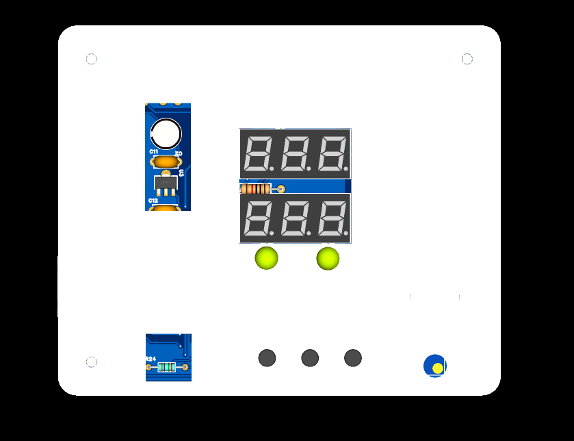
; 3. Front view.


 京公网安备 11010802033920号

 ZPSD413A1-C-15J


