The intelligent household waste sorting device should have the functions of automatically identifying, classifying and disposing of the waste into the corresponding
trash cans , compressing the waste, triggering a full-load alarm, and playing a self-designed and produced waste sorting promotional video. Communication and control of the sorting device via any interactive means
are not permitted.
Considering the relatively small number of microcontroller pins required, the harsh environment (in a trash can) and potential for significant current draw, we ultimately selected the CW32F030C8T6 as the main controller chip. Some parameters are as follows:
Simultaneously, due to the need for extensive deep learning computations in this design, we selected the Orange Pi 5 as the visual recognition host computer. Some parameters are as follows:
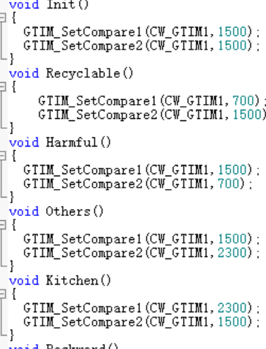
We selected a dual-axis servo motor for precise control of the trash dumping device's angle.
We selected a high-precision phototube sensor to detect the full load of trash.
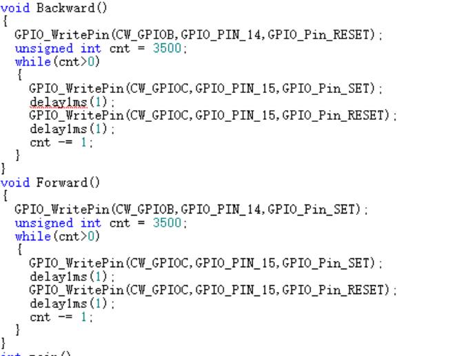
To improve the torque during compression, we used a lead screw + stepper motor to drive the trash compression device.
: Power supply: We used a 7V model aircraft battery for power. First, the 7V supply voltage was stepped down to 5V using an LM2596-5V DCDC step-down chip to power the phototube.
To ensure stable chip power supply voltage, we selected the LM1117 LDO voltage regulator chip for the 5V to 3.3V step-down solution, resulting in lower ripple.
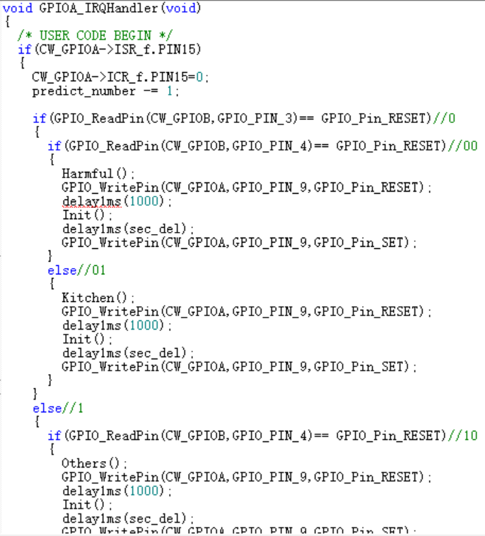
For chip programming, we chose the CH549G chip as the embedded DAP-Link, allowing direct programming via a Type-C data cable; while retaining the traditional SWD four-wire interface for use with a wireless programmer. The overall
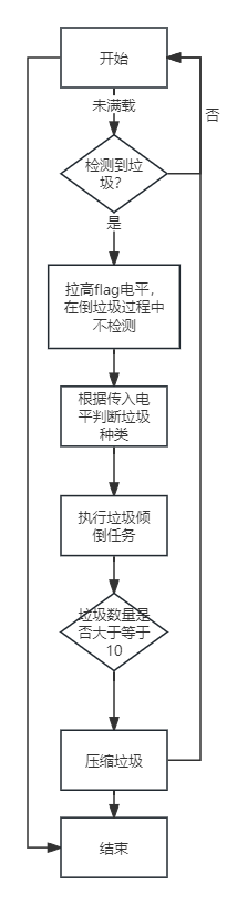
software design flowchart shows the actions performed by the servo motor when different types of waste are detected, the actions performed by the stepper motor when the waste is full, and the waste type detection code in the interrupt .
The STLink V3 MiniE adapter board uses a jumper wire to connect to the STLink's USB port, allowing direct use of a single USB port.
5P programming interface definition: RST SWCLK SWDIO GND VCC.
Has impedance matching been performed? If so.
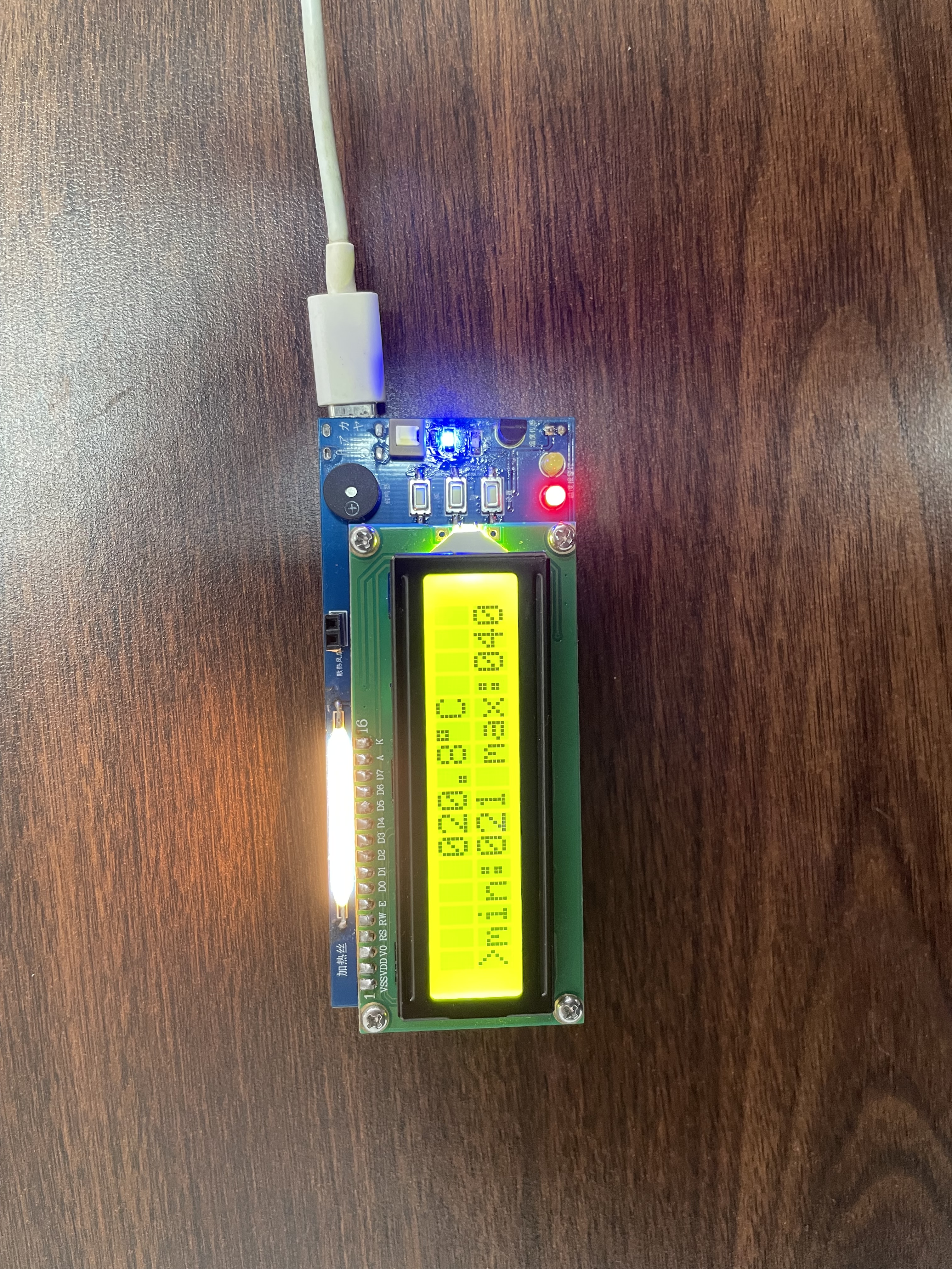
A temperature warning system designed based on an 89C51 microcontroller and a DS18B20 digital sensor uses an LCD1602 for display and allows users to set upper and lower temperature limits and activate corresponding human-machine interface functions.
I. Design Summary
The system's hardware consists of an ST89C52 microcontroller, a DS18B20 temperature sensor, and an LCD screen. The ST89C52 microcontroller serves as the core of the system, responsible for controlling and processing temperature data and performing corresponding actions based on the set alarm range. The temperature sensor measures the ambient temperature and transmits the temperature data to the microcontroller. The LCD screen displays the ambient temperature and other relevant information.
II. Overall Design Block Diagram

III. Hardware Circuit Composition
1.
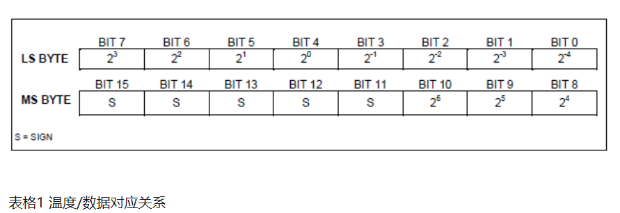
DS18B20 The DS18B20's temperature output data is calibrated in Celsius; for Fahrenheit applications, a lookup table or conventional data conversion can be used. Temperature data is stored in the temperature register as a 16-bit flag-extended two's complement number (see Figure 2). Sign Flag (S): Temperature polarity: S=0 for positive, S=1 for negative. If the DS18B20 is defined with 12-bit conversion precision, all bits in the temperature register will contain valid data. If it is 11-bit conversion precision, bit 0 is undefined. If the conversion precision is 10 bits, then bits 1 and 0 are undefined. If the conversion precision is 9 bits, then bits 2, 1, and 0 are undefined. Table 1 shows the relationship between temperature output data and corresponding temperatures under 12-bit conversion precision. The
event sequence for accessing the DS18B20 is as follows:
Step 1: Initialization
Step 2: ROM command (following any data exchange request)
Step 3: DS18B20 function command (following any data exchange request)
Each access to the DS18B20 must follow these steps; if any of these steps are missing or not executed, the DS18B20 will not respond, except for the ROM search command [F0h] and the alarm search command [ECh]. After executing these ROM commands, the master device must return to Step 1 above.
Initialization
All events on the 1-Wire bus must begin with initialization. The initialization sequence consists of a reset pulse issued by the master device on the bus followed by a presence pulse in response from the slave device. The response pulse informs the master device on the bus that a slave device (e.g., DS18B20) is present and ready to operate.
ROM commands
are executed by the master device upon detecting the presence pulse. These commands operate on a unique 64-bit ROM code for each device, allowing identification of multiple devices connected to the bus. These commands also allow the master device to determine the number and type of devices on the bus, or devices with temperature alarm signals. There are a total of five ROM commands, each 8 bits long. The master device must execute an appropriate ROM command before executing any DS18B20 function commands.
Search ROM [F0h]
: After system power-on initialization, the master device must identify the ROM codes of all slave devices on the bus to determine their type and number. Learning the ROM codes is a clearing process; the master device must cyclically send the Search ROM [F0h] command (which accompanies data exchange) to identify all slave devices on the bus. If there is only one slave device on the bus, a simpler read ROM command (explained in detail in the next paragraph) can replace the ROM search process.
Read ROM [33h]
This command can only be used when there is only one slave device on the bus. This command allows the master device on the bus to read the slave device's 64-bit ROM code without the ROM search command process. When there is more than one slave device on the bus, sending this command will cause a data conflict when all slave devices respond.
Match ROM [55h]
This match ROM command followed by sending a 64-bit ROM code allows the master device on the bus to match a specific slave device. Only slave devices that fully match the 64-bit ROM code will respond to function commands issued by the master device on the bus; other slave devices on the bus will wait for the next reset pulse.
Skip ROM [CCh]
The master device can use this command to simultaneously send a command to all slave devices on the bus not to send any ROM code. For example, by sending a skip ROM command to all DS18B20s on the bus followed by a temperature conversion [44h] command, all devices will simultaneously perform temperature conversion.
It's important to note that when there's only one slave device on the bus, the Read Scrambling Register [BEh] command can be followed by a Skip ROM command. In this case, the master device can read data from the slave device without sending 64-bit ROM encoding. When there are multiple slave devices on the bus, if the Read Scrambling Register command is sent after the Skip ROM command, all slave devices will start transmitting data simultaneously, causing data collisions on the bus. The
Alarm Search [ECh]
command operates similarly to the Skip ROM command, but only slave devices with the alarm flag set will respond. This command allows the master device to determine if any DS18B20 had a temperature alarm during the most recent temperature transition. After all alarm search commands have been executed in a loop, the master device on the bus must return to the first step (initialization) of the event sequence.
DS18B20 Function Commands
: When the master device on the bus has determined which DS18B20 can communicate via ROM commands, it can send function commands to one of the DS18B20s. These commands allow the master device to write or read data from the DS18B20's scratch register, initialize temperature transitions, and define power supply modes. The DS18B20's functional commands are described in detail below.
Temperature Conversion [44h]
This command initializes a single temperature conversion. After the temperature conversion is complete, the converted data is stored in a 2-byte temperature register in the temporary register, after which the DS18B20 returns to a low-power idle state. If the device is in "parasitic power" mode, the master must force the data line high during the temperature conversion 10µs (maximum) after this command is executed (described in the "DS18B20 Power Supply" section). If the device is in external power mode, the master can execute the data read timing after the temperature conversion command; if the DS18B20 is in the process of temperature conversion, it will respond with a 0 level; if the temperature conversion is complete, it will respond with a 1 level. In "parasitic power" mode, because the bus is forced high throughout the temperature conversion, the above response will not occur.
Write to Temporary Register [4Eh]
This command causes the master to write 3 bytes of data to the DS18B20's temporary register. The first byte of data is written to the TH register (Byte 2 of the temporary register), the second byte is written to the TL register (Byte 3), and the third byte is written to the configuration register (Byte 4). All data must be sent in a least significant byte-first manner. The master device must reset the slave device before writing any three bytes of data; otherwise, the data will be corrupted.
Reading the Temporary Register [BEh]
: This command allows the master device to read the value stored in the temporary register. Data is transferred starting from the least significant byte of Byte 0 until the 9th byte (Byte 8 - CRC) is read. If the master device only needs a portion of the data in the temporary register, it can terminate the read operation by resetting.
Copying the Temporary Register [48h]
This command copies the values of TH, TL, and configuration registers (Bytes 2, 3, and 4) from the temporary storage register to the EEPROM. If the device uses a "parasitic power" mode, the master device must force the 1-Wire bus high for more than 10ms within 10µs (maximum) after this command is sent. The
EEPROM recall command [B8h]
recalls the temperature alarm trigger values (TH and TL) and configuration register data from the EEPROM to Bytes 2, 3, and 4 in the temporary storage register. The master device can execute a data read sequence after the EEPROM recall command. If the DS18B20 is in the process of recalling the EEPROM, it will respond with a 0 level; if the recall is complete, it will respond with a 1 level. The data recall operation is automatically performed once after power-on initialization, so the temporary storage register will always contain valid data during power-on. The DS18B20 uses a strict 1
-
Wire bus communication protocol to ensure data integrity. The protocol defines several signal formats: reset pulse, presence pulse, write 0, write 1, read 0, read 1. The master device executes all signals except the presence pulse.
Initialization Procedure—Reset and Presence Pulse
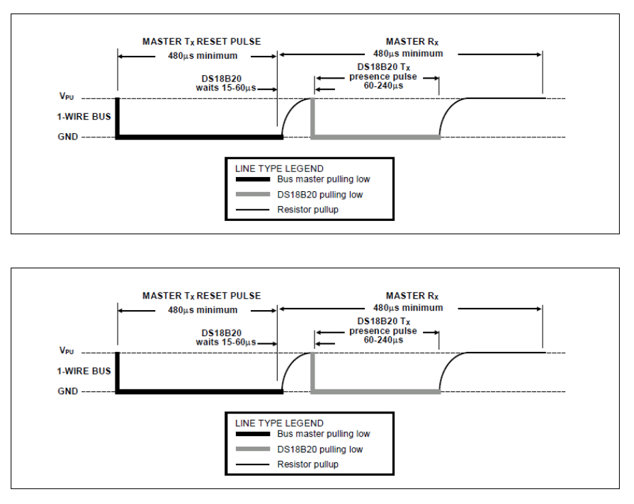
: All communication with the DS18B20 begins with an initialization sequence consisting of a reset pulse from the master device and a presence pulse in response from the DS18B20, as shown in Figure 13. When the DS18B20 responds to the presence pulse of the reset signal, it indicates to the master that it is on the bus and ready to operate.
During the initialization sequence, the master on the bus sends a (TX) reset pulse by pulling the 1-Wire bus low for more than 480µs. The master then releases the bus and enters receive mode (RX). After the bus is released, a pull-up resistor of approximately 5kΩ pulls the 1-Wire bus high. When the DS18B20 detects this rising edge signal, it waits 15µs to 60µs and then sends a presence pulse by pulling the 1-Wire bus low for 60µs to 240µs. During
read/write periods,
the master device writes data to the DS18B20 during write periods and reads data from the DS18B20 during read periods. Only one bit of data can be transmitted per read/write period on the 1-Wire bus. There are two types of
write
periods: "Write 1" and "Write 0". The master device writes a logic 1 to the DS18B20 during the "Write 1" period and a logic 0 during the "Write 0" period. Each write period must have a minimum duration of 60µs, and there must be at least a 1µs recovery time between independent write periods. Both write periods are initialized by the master device by pulling the 1-Wire bus low (see Figure 14).
To form a "Write 1" period, the master device must release the bus within 15µs after pulling the 1-Wire bus low. After the bus is released, a 5kΩ pull-up resistor pulls the bus high. To form a "Write 0" period, the master device must keep the bus low for the entire period (at least 60µs) after pulling the 1-Wire bus low.
After the master device initializes the write period, the DS18B20 samples the bus within a time window of 15µs to 60µs. If the bus is high during the sampling window, logic 1 is written to the DS18B20; if the bus is low, logic 0 is written to the DS18B20. The DS18B20 can only transmit data to the master device during the read
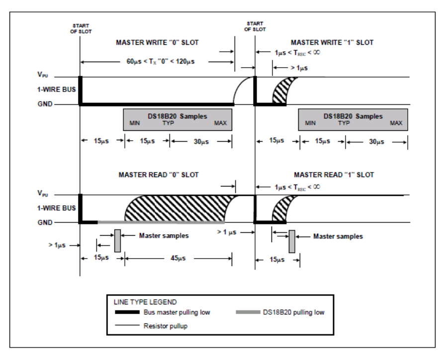
period
. Therefore, the master device must generate a read period promptly after executing the read temporary register [BEh] or read power mode [B4h] command so that the DS18B20 can provide the required data. Additionally, the master device can generate a read period after executing the temperature conversion [44h] or copy EEPROM [B8h] command to obtain the operational information mentioned in the "DS18B20 Function Commands" section. Each read
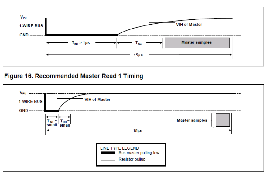
period must have a minimum duration of 60µs, and there must be at least a 1µs recovery time between independent write periods. The read period is initialized by the master device pulling the bus low for more than 1µs and then releasing it (see Figure 14). After the master device completes the read period initialization, the DS18B20 will send either a 0 or a 1 to the bus. The DS18B20 sends a logic 1 by pulling the bus high and a logic 0 by pulling the bus low. After sending a 0, the DS18B20 will release the bus, and the bus will return to a high-level idle state through the pull-up resistor. The data output from the DS18B20 has only a 15µs validity period after the initial read timing. Therefore, the master device must release the bus and sample the bus within 15µs after starting the read period.
2. The power supply
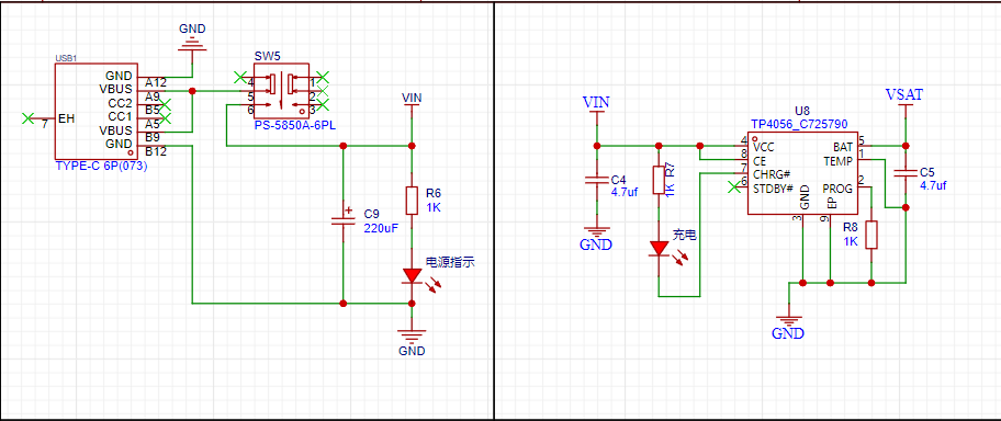
circuit adopts USB-C power supply and supports lithium battery power supply (the lithium battery voltage should not be lower than 3.5V, otherwise it will cause the voltage to be too low and the chip will not work properly).

The circuit switching adopts a P-channel MOSFET, which can realize seamless automatic switching between external power supply and battery power supply.
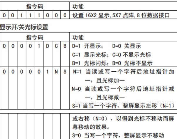
3. LCD1602

wiring diagram,

initialization
read timing diagram,
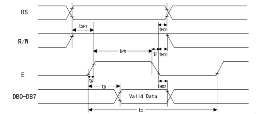
and write timing diagram.

4. Human-machine interaction:
After the alarm is triggered, the corresponding high temperature and low temperature interfaces will output a CMOS high level, which can be used to control the high load circuit through an external relay.

This solution has been verified by physical testing and can be directly soldered onto a PCB. Most components are surface-mount devices.
IV. Physical Demonstration
: Side View -
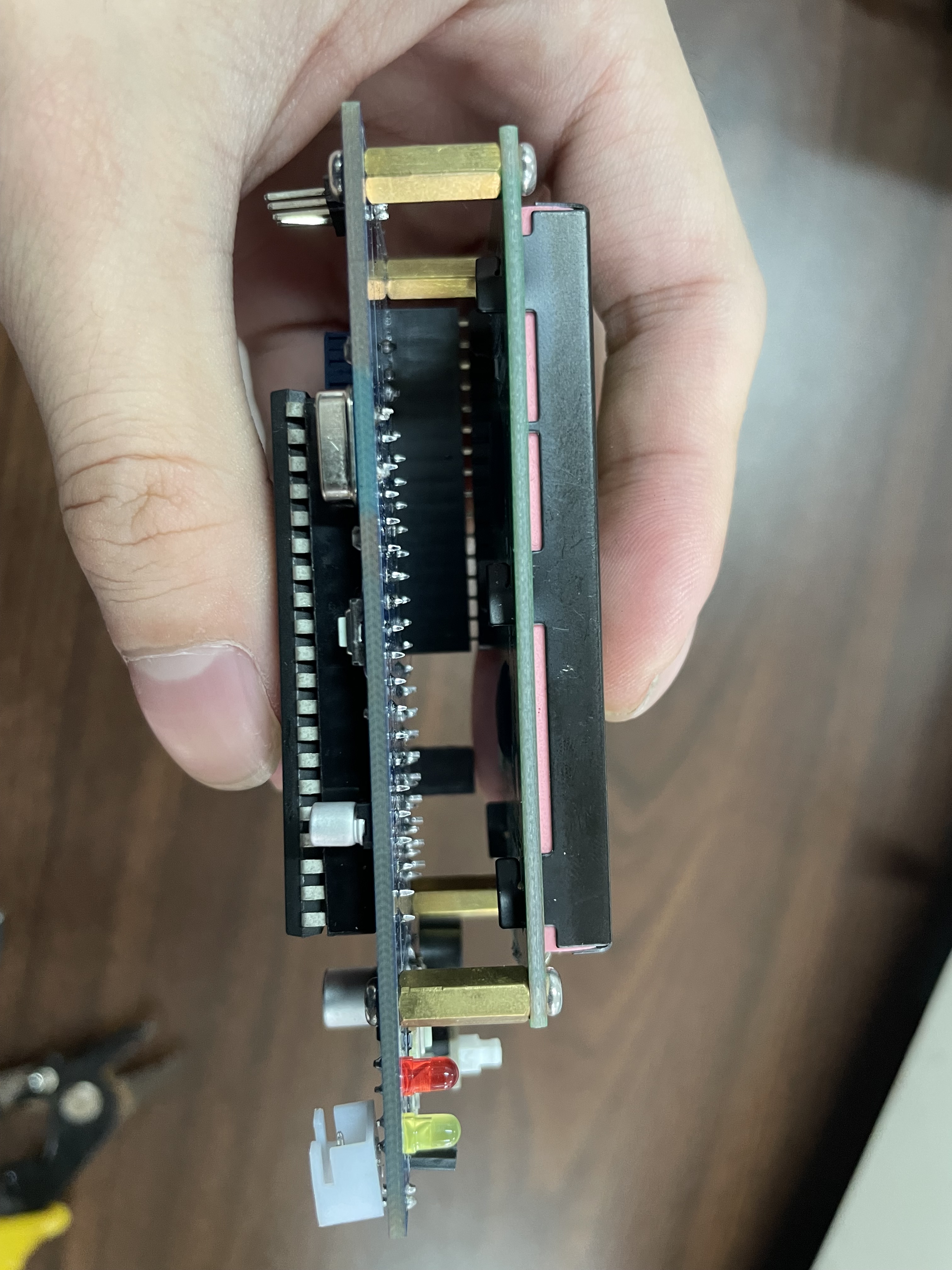
Low Temperature Alarm Indicator
main.hex
Simulation image.png
IMG_9482 - (16x9)_1~1.mp4
PDF_DS18B20 Temperature Detector.zip
Altium_DS18B20 Temperature Detector.zip
PADS_DS18B20 Temperature Detection.zip
BOM_DS18B20 Temperature Detection.xlsx
97208
CH32V307 core board
1. The pinout and PCB layout of the CH32V307VCT6 are fully compatible with the STM32F103VCT6. 2. The MCU has a main frequency of 144MHz; 256KB Flash memory; and 64KB RAM. 3.
1. The pinout and PCB layout of the CH32V307VCT6 are fully compatible with the STM32F103VCT6. 2. The MCU clock speed is 144MHz; Flash memory is 256KB; RAM is 64KB. 3. The basic program download method for the CH32 is exactly the same as that for STM32; serial port download uses PA9 and PA10; SWD download uses PA13 and PA14 (the CH32 uses a WCH-Link programmer). 4. The CH32's two USB ports also support downloading (PA11, PA12; PB6, PB7). 5. The CH32V307VCT6 integrates an Ethernet PHY, which can be directly connected to an external network adapter (e.g., HR911105A), providing complete API functions for TCP, UDP, DHCP, DNS, etc.
PDF_CH32V307 core board.zip
Altium_CH32V307 core board.zip
PADS_CH32V307 core board.zip
BOM_CH32V307 Core Board.xlsx
97209
Two-wheel drive tracking small car board
The main control board of the car uses infrared detectors for line tracking.
The car control motherboard, which uses infrared detectors for tracking,

can start normally after being connected to an OLED, an STM32 chip, and an LM2596. However, the MPU6050 has not yet arrived, so it cannot be verified at this time, but it is basically certain that it can be used normally.
WeChat image_20231107160805.jpg
WeChat image_20231107160820.jpg
PDF_Two-Wheel Drive Tracking Car Board.zip
Altium 2WD Tracking Mini Car Board.zip
PADS_2WD Tracking Car Board.zip
97210
Renesas-based clock/ebook
Building upon the previous project, this project adds a TF card module, SPI FLASH, EEPROM, and a power detection module, enabling functions such as forecast acquisition, network time synchronization, and computer communication. Suitable for beginners and those seeking advanced practice, this project is entirely open source. The source code (e2) can be obtained upon request.
1. Project Function Introduction:
This project is an upgrade of the summer training camp project (Project: #8th LCSC Electronics Design Contest# Desktop Clock Design Based on Renesas - LCSC EDA Open Source Hardware Platform (oshwhub.com)). Building upon the previous project, it adds a TF card module, SPI FLASH, EEPROM, and a power detection module, enabling functions such as time forecast acquisition, network time synchronization, and computer communication. Suitable for beginners to advanced learners, this project is entirely open source; contact us to obtain the source code (e2) if needed.
1. Display and set basic information such as time, year, month, and day (time can be manually adjusted or synchronized over the network, already implemented);
2. Support memory card detection and read/write (SPI mode);
3. Support WIFI connection, support image and text transmission with a computer over the network, and update the font library using a computer via WIFI;
4. Support EEPROM, use EEPROM to store device information;
5. Support SPI FLASH, store font library, images, and other information;
6. Support weather acquisition, including current day information and forecasts for the next three days;
7. Obtain indoor temperature and humidity via DHT11;
8. Transmit images and update the font library via a host computer.
4. The hardware section
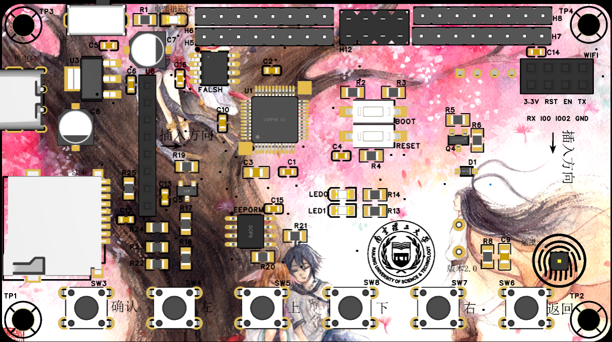
uses the Renesas F7RA2E1A72DFL chip, involving power supply circuits, a power detection module, a download circuit, a step-down circuit, a lithium battery charging circuit, a DHT11 temperature and humidity sensor for indoor temperature and humidity acquisition, an ST7735S 1.77-inch TFT LCD for display, and an ESP-01S wireless module for communication (using AT communication, capable of communicating with a computer to update fonts and images). Other components include six independent buttons, a buzzer module, an EEPROM module, and an SPI FLASH module. Furthermore, the board exposes all GPIO pins, allowing it to be used as a desktop clock or as a core board/development board. The following are the schematics and descriptions of each module (only newly added modules are described).
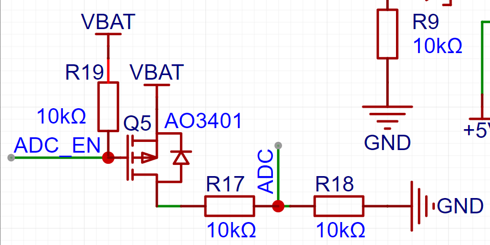
When ADC_EN is pulled low, VBAT is connected to the ADC, allowing power acquisition through the ADC pin. When not pulled low, ADC_EN is pulled high, saving battery power.
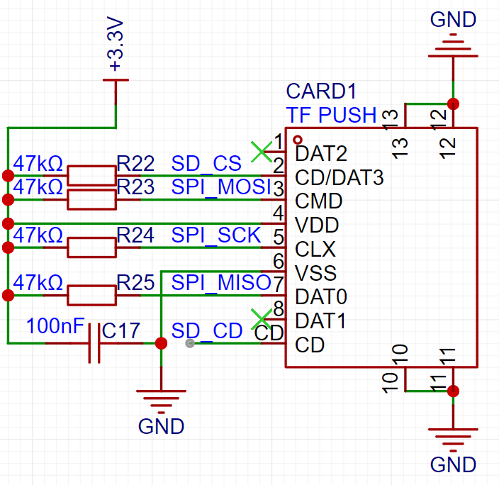
The SD card module's SD_CD pin is optional. When a memory card is inserted, the SD_CD pin connects to the casing and is at a low level, but it's not pulled high, making it unstable. Furthermore, you can check for responses by reading and writing to the SD card, so the SD_CD pin is unnecessary.
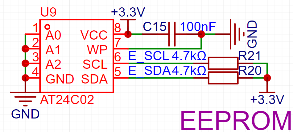
The AT24C02 is chosen; it can store 256 bytes and can be used to store clock device status, Wi-Fi passwords, etc., preventing data loss after power-off.
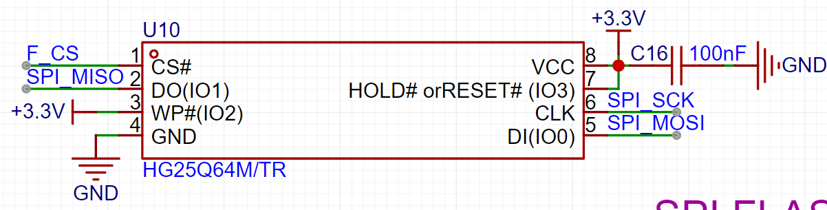
The 25Q64 is chosen; its package is SOP-8, but most packages seem to be SOP-8-225. Both pins are the same, but the sizes differ. If using this package, please pay attention to the size; otherwise, you may need to use jumper wires.
The following is the complete schematic:
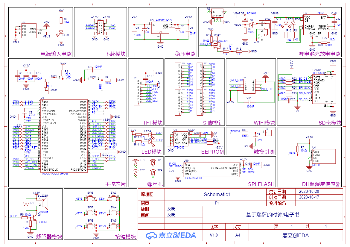
The touch pin in the schematic is unusable. If you need to use the touch pin, you need to add power to pin 112. This was omitted in the design; you can modify it if needed.
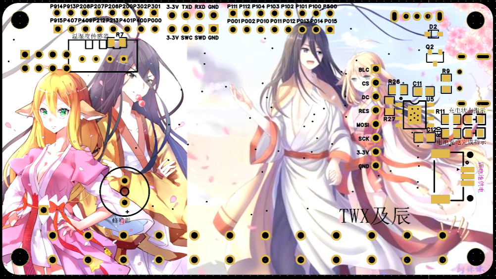
PCB Appearance:
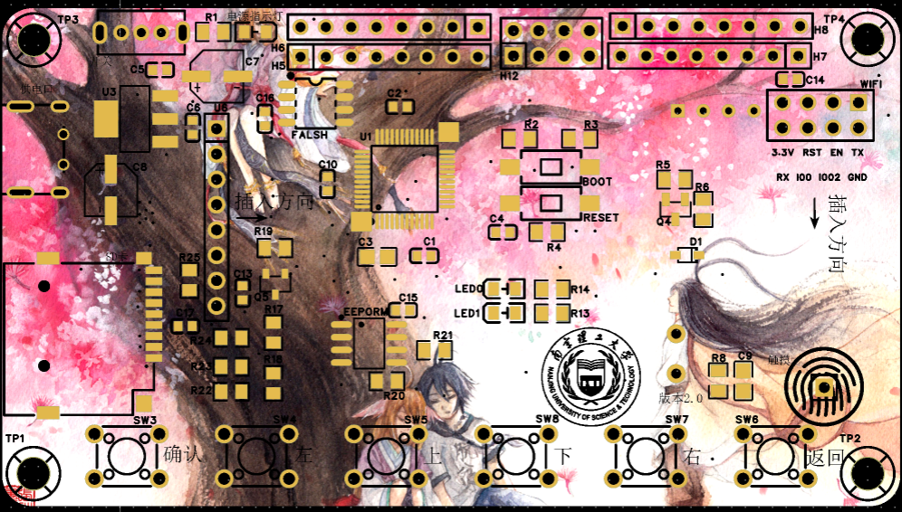
Note that the Type-C connector used here is from Hanrong. When purchasing, I found that Hanrong's Type-C connectors have reversed positive and negative terminals compared to most domestic manufacturers. If using this connector, please purchase Hanrong's Type-C connector or modify the schematic (reverse the positive and negative terminals; testing before soldering is recommended to prevent component burnout).
3D Front

View:
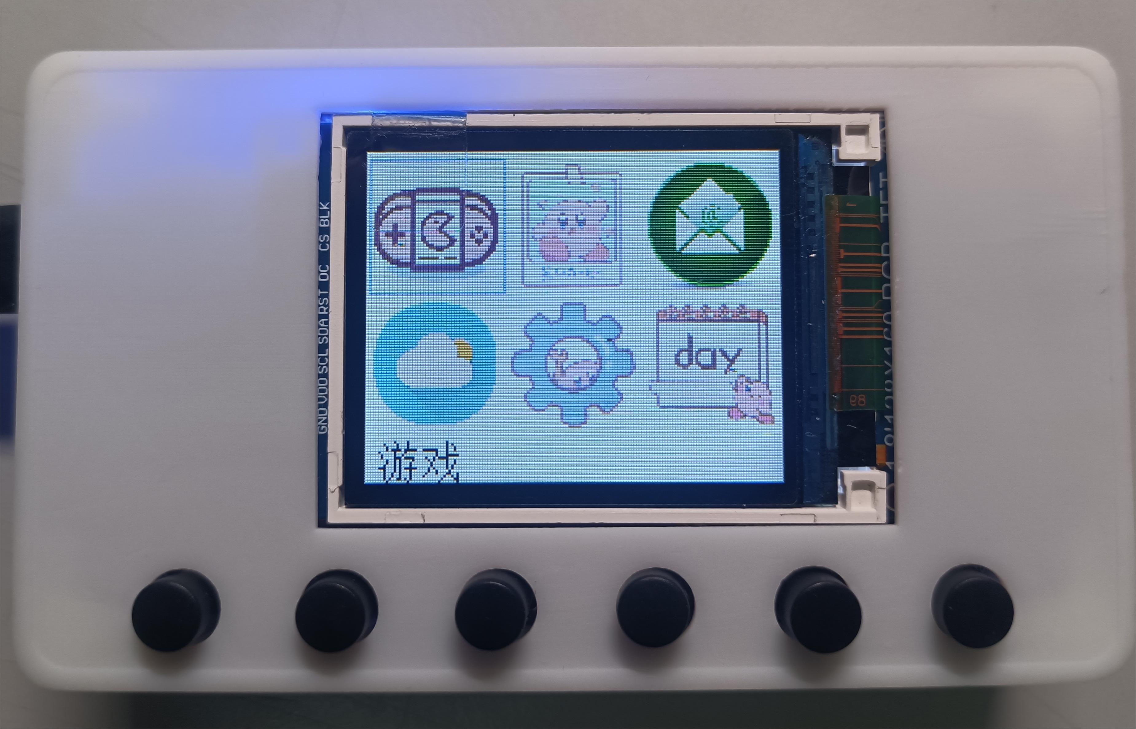
An additional panel can be added to cover more of the screen.
5. Software


Video Introduction:
[Rensas Clock/E-book Production] https://www.bilibili.com/video/BV1gu4y1b7Pc?vd_source=8fbcb5e945ef64ba122b163c354a4880
C++ code is also available upon request. Currently, the host computer is a console program; MFC is under development.
PDF_Rensas-based Clocks - eBook.zip
Altium_Rensas-based Clock_eBook.zip
PADS_Rensas-based Clocks_eBook.zip
BOM_Rensas-based Clocks_eBook.xlsx
97211
Simple Digital Oscilloscope [Training Camp 2023.10]
[Beginner Learning Period] This is an oscilloscope + signal source analog front-end expansion board designed for use with the H750 core board.
It mainly includes an analog input section with 2MSPS/100KHz (sampling rate/bandwidth) and an analog output section with 1Hz - 20KHz.
Physical demonstration link on Bilibili: https://www.bilibili.com/video/BV1B94y1n7G7
Foreword: 1. For detailed technical documentation, please refer to the official documentation of "Hardwood Classroom" - Simple Oscilloscope (yuque.com); 2. Capacitors C27, C28, C29, and C30 may cause inaccurate peak-to-peak value measurements, and it is recommended not to solder them;
I. Project Description
This is an oscilloscope + signal source analog front-end expansion board used with the H750 core board. Its main functions and characteristics:
1. Analog input section
: Number of channels: Synchronous dual-channel
Sampling rate/bandwidth: 2MSPS/100KHz
Input range: ±10mV - ±15V
Input impedance: 1MΩ
2. Analog output section
: Number of channels: 1
Output signal waveform types: Sine wave, square wave, triangle wave
Output sine wave frequency: 1Hz - 20KHz
Output range: ±10mV - ±10V
Output impedance: 50 ohms
Output current capability: ±10mA
II. Power supply section
1. Type C interface
Type C interface basics: USB Type C interface pin details - Zhihu (zhihu.com)
16P Type C power supply wiring (6P Type C is recommended for power supply only)
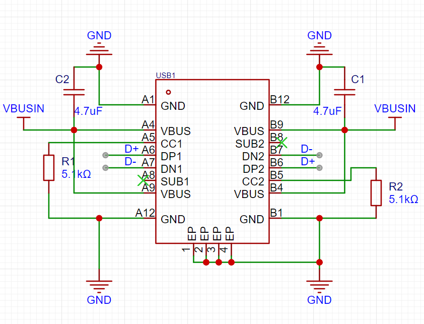

Figure 2.1 Type C power supply wiring diagram
Figure 2.2 Encoder wiring diagram
Note: 1. VBUS must be grounded through a capacitor (filtering); 2. When CC1/2 is not used, it must be grounded through a 5.1kΩ resistor;
2. Power supply module

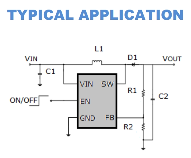
Figure 2-3 Power supply module schematic diagram
Figure 2-4 MT3608 Typical Application Circuit
Notes: MT3608 detailed technical documentation: MT3608.pdf (szlcsc.com) //or MT3608L (can be used as a substitute in this example): MT3608L.pdf (szlcsc.com)
3. The encoder
is shown in Figure 2.2. Hardwood Classroom Encoder Debugging Tutorial: Chapter 4 Changing the Vertical and Horizontal Axes (yuque.com)
III. Important Display Section

(White Screen Display): My personal project progress was delayed for a long time due to the screen section. The main problem was that the screen displayed a white screen. The Hardwood Classroom official documentation also has detailed test steps in this section. Please refer to the LCD test section in Chapter 2, Fast Refresh (yuque.com). It is recommended to directly measure the waveform of the pins of the screen socket to prevent problems caused by poor soldering or contact. Under normal circumstances, the output of the core board will not have problems.
Figure 3.1 Schematic diagram of the 2.8-inch display screen welding circuit.
IV. Input/Output Section.
The official engineering documentation for this section is very detailed. As a novice, I won't presume to explain further here. Please refer to the open-source platforms: [Hardwood Classroom] AFE03 Oscilloscope Signal Source Expansion Board - JLCPCB EDA Open Source Hardware Platform (oshwhub.com); Hardwood Classroom: Hardware Design (yuque.com).
PDF_Simple Digital Oscilloscope [Training Camp 2023.10].zip
Altium Simple Digital Oscilloscope [Training Camp 2023.10].zip
PADS_Simple Digital Oscilloscope [Training Camp 2023.10].zip
BOM_Simple Digital Oscilloscope [Training Camp 2023.10].xlsx
97212
STM32F407ZGT6 (ZET6) Color Silkscreen Development Board (Verified)
This development board, themed around the Arknights character Shining Owl/Rhine Labs, features a color silkscreened STM32F407ZGT6/ZET6 main controller. It includes onboard flash memory, EEPROM, serial-to-TTL converter, DC-DC step-down functionality
, and all I/O ports are exposed. All functions have been verified to be working correctly.
A system board designed based on the STM32F407ZGT6 (compatible with STM32F407ZET6) main control chip.
This system board integrates
a TPS5450 DC-DC step-down converter (maximum 35V input -5V/5A output) and a reserved Type-A port for powering the Raspberry Pi (5V/3A).
It also includes an AMS1117-3.3 LDO step-down converter (5V input -3.3V/1A output) to power the chip.
The FLASH chip is a W25Q128,
the EEPROM chip is an AT24C02
, the serial-to-TTL converter is a CH340N (Type-C)
, and it features four buttons and an LED (for function verification). An interface for a 2.4-inch SPI touchscreen module is also provided.
The design incorporates a white owl and Rheinmetall theme and uses JLCPCB color silkscreen printing (the design is quite ugly, please be gentle with your criticism).
All I/O ports are brought out (including pre-occupied pins), and the operating status of the FLASH and EEPROM chips can be adjusted via an 8-bit DIP switch.
All functions except for the 2.4-inch screen module have been verified and are operating normally.

The power supply layout is very dense; hand soldering with a soldering iron is extremely tedious (I'm fuming!). If possible, avoid hand soldering, or simply don't solder the TPS5450 section at all—it's too painful.
Avoid multi-channel power supply; if you're using Type-C power, don't supply power to other ports.
PDF_STM32F407ZGT6(ZET6) Color Silkscreen Development Board (Verified).zip
Altium_STM32F407ZGT6(ZET6) Color Silkscreen Development Board (Verified).zip
PADS_STM32F407ZGT6(ZET6) Color Silkscreen Development Board (Verified).zip
BOM_STM32F407ZGT6(ZET6) Color Silkscreen Development Board (Verified).xlsx
97214
Replica Multifunctional Test Pen
Perfect replica – Dot Crystal Multifunctional Test Pen.
Replicating He Diangong's Multifunctional Test Pen: Dianjing - CW32 Multifunctional Test Pen - JLCPCB EDA Open Source Hardware Platform (oshwhub.com)
As an electronic information engineering student, I absolutely cannot allow myself to simply copy schematics without understanding them and consider the board finished. I find it difficult to participate in a training camp like that. I hope to hone my skills and experience through the training camp. Therefore, in the first few days, I carefully studied the project principles by referring to the explanations of each module in He Diangong's open source documentation. This process took some time, so I started a little late, but my understanding of the entire project became deeper, laying a solid foundation for debugging board problems later.
Although this training camp did not provide step-by-step schematic drawing and explanations, He Diangong's open source documentation provided a very detailed introduction to each module, which benefited me greatly.
Since He Diangong's documentation already explains the principles in detail, I will not repeat them here, but only discuss some minor problems and details encountered during the replication process.
It basically perfectly replicated this project, but the original design by He Diangong was a two-layer board with tight wiring, so a wire had to be run from the analog ground to the tail plug. For someone like me with OCD, I couldn't accept this kind of wire. So, I changed the board to a four-layer board and added two internal power layers, namely AGND and GND. This way, the tail plug doesn't need a wire, and the two ground layers will make the circuit more stable.
PCB design considerations:
1. Schematic
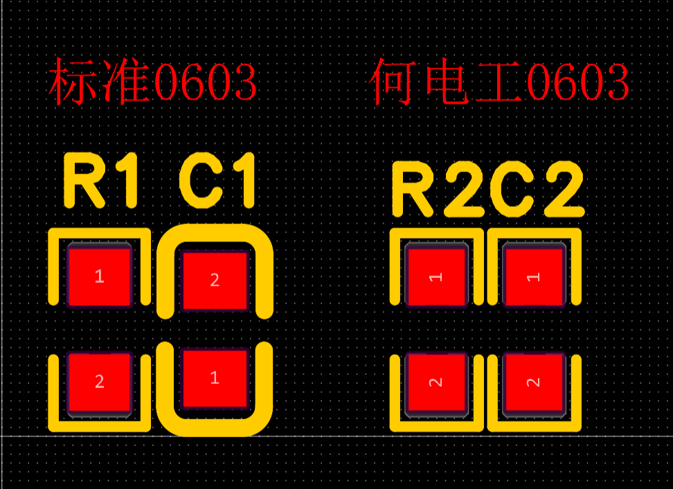
(1) The first problem I found in the PCB layout was that, due to the compact layout, He Diangong used a redrawing scheme for the 0603 resistor and capacitor package. The redrawn resistor and capacitor package by He Diangong was slightly smaller than the standard package, but the size of the resistor and capacitor package was the same. This made me, with OCD, extremely comfortable when laying out the layout later. My personal suggestion is to just copy the one drawn by He Diangong and use it directly.
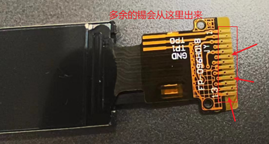
(2) Here is a small problem. My screen cable is a bit short, so I had to break several screens to fit the casing. I personally suggest that the screen cable package be moved up a bit. See the blue arrow in the figure below.

2. PCB
(1) Layout: Since it was someone else's project, although I spent time familiarizing myself with the schematic diagram beforehand, my familiarity with the definitions of each component and the MCU's I/O ports was definitely less than that of the designer. At first, I thought I could just lay out the four-layer board randomly. If it didn't work out, I could just add more vias. There were no high-speed signals, so it shouldn't have a big impact. But after I started routing, I found that the area on the board was too tight, so there was no place to put vias in some places. So I overturned the original plan and started over. I referred to the layout of He Electric's PCB. After the layout, there were far fewer network crosses than before, which made the subsequent routing much easier.
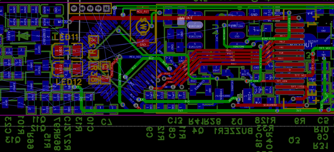

(2) Wiring: A good layout can make your wiring a simple connect-the-dots game, so it is recommended to spend more time on the layout, which will make the wiring much simpler. I use 15mil for power lines and 10mil for others. In places where it is really tight, I use 8mil.
(3) Others: I personally suggest that you need to re-solder the battery BAT and GND pads to be slightly larger and keep them a certain distance away from the TP4057. I only placed the BAT pad, and it was slightly smaller. In the end, I chose to connect the BAT directly to the pin of the TP4057. However, due to the frequent removal and placement during testing, the TP4057 was short-circuited and burned out multiple times. (After fixing other problems, I found that it could not charge. I spent a long time looking for the problem. It is really fragile. I cried.) The charging voltage of the TP4055 should be stable at around 4.25V. If you find that it is around 5V when you plug in the charger, it is short-circuited and burned out. Remember to make teardrops. I always forget.
3. Soldering and debugging:
(1) First of all, you must use the soldering auxiliary tools of LCSC. They are really convenient. I personally used a hot air gun and solder paste throughout the process. Although the soldering is slow, I suggest you solder carefully and slowly. It is much faster than soldering the wrong part or finding the short circuit bit by bit later.

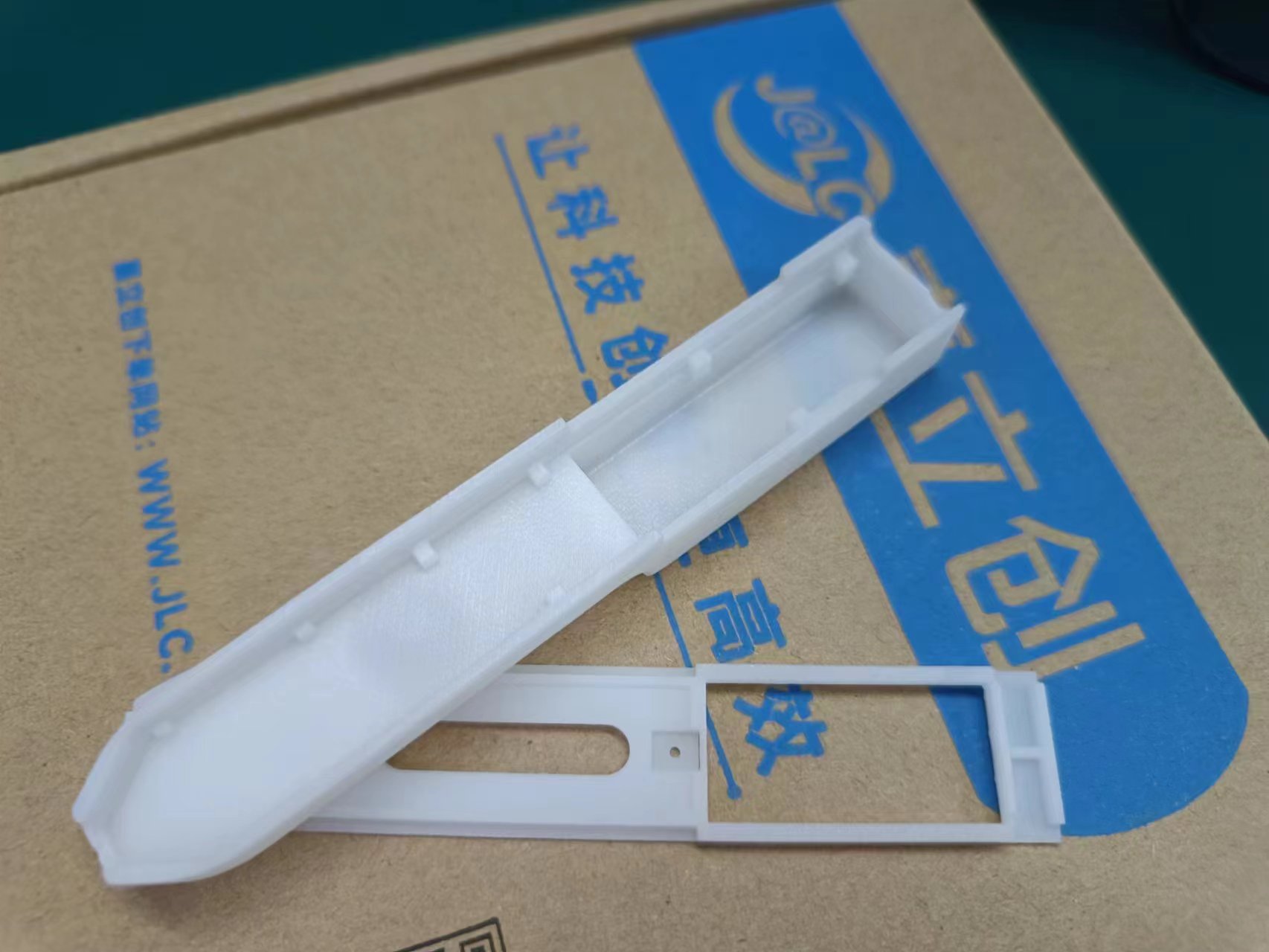
4. 3D shell: I am still a student and I don't have much money. Although I can use Blender to do 3D modeling, it is very likely that I will have to make multiple prototypes and modifications, which is costly. Therefore, I finally chose to use the open-source shell that He Electric has verified. With a little modification, it can be matched with my PCB.
Here are some details that I might make to the open-source shell of He Electric if I spend time modeling:
(1) Add holes for placing probes on the shell. This makes it easy to hide the probes in the shell when going out and take them out when needed.
(2) Design a clip that can be covered to protect the probe sleeves that cannot be removed. As it is now, it is very easy to bend. The shell is still fixed by water, which makes it difficult to replace. When redesigning, the shell thickness should be maintained and the snap-on closure should be optimized as much as possible.
5. Let me introduce the CW32 MCU. The CW32F0303C8 is an excellent domestic MCU. I previously received a small blue board from the CW32 ecosystem community and used it briefly, so debugging and programming with Keil this time went much more smoothly.
1. Later, I encountered a problem with a poor-quality screen that wouldn't light up the backlight. While troubleshooting, I repeatedly removed and resoldered it using a 380°C hot air gun, and the MCU performed normally throughout.
2. Once, when I soldered the MCU_VCC to a nearby pin, the screen lit up the CW logo before going black, even with a short circuit. (Seriously, I was devastated!)
3. Even right after soldering, before the temperature had fully cooled down, it could light up the logo normally, and after an automatic restart, it would still work normally even when the board was noticeably hot to the touch.
This isn't just empty praise.

Finally, a wishful thought:
could a simple oscilloscope function be added? I also can't use a larger screen, otherwise, I'd lose its compact and convenient advantages. My proposed solution is to use Wi-Fi or Bluetooth to output the waveform to a mobile phone. This way, even when out and about, I can measure simple waveforms without sacrificing portability.
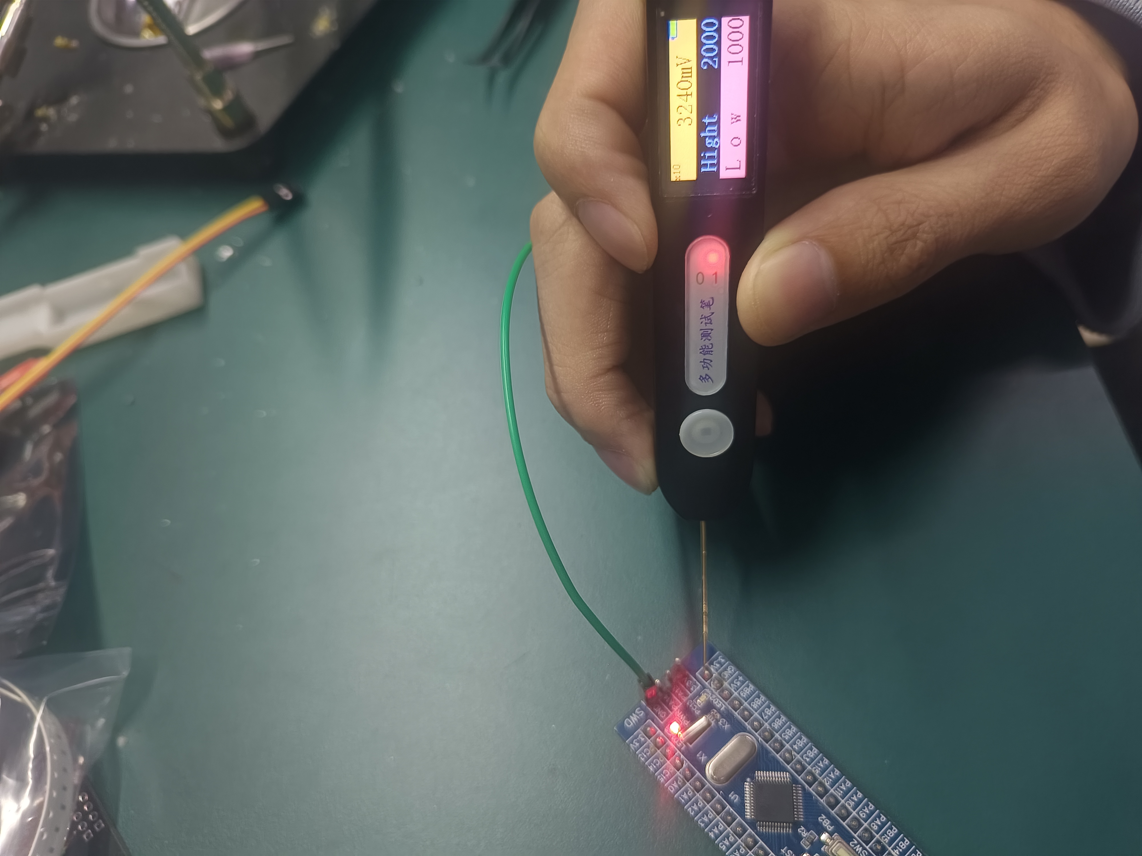
Here are some finished product images:
I see many people in the group haven't finished soldering and debugging their boards. I'm not an expert, but I'll still write down some soldering and debugging precautions here, hoping to help everyone.
First, when soldering, the resistors and capacitors of various types must not be soldered incorrectly. Refer to the soldering assistant mentioned above in detail. Note that after soldering, the first thing to check is to see if there is any solder bridging that could cause a short circuit.
Secondly, the testing approach is to test each board one by one according to its different functions. In many cases, a certain part is not working properly, so I've written down the precautions for testing each module below. For testing a single board, the general approach is to first check if there are any problems with the schematic design. If not, use a multimeter to test step by step.
1. TP4057 charging module:
First, the TP4057 module can be tested without soldering the battery. If this part of the circuit works normally, the green LED will light up when the TYPE-C power supply is plugged in (note that you should use a mobile phone charger and try not to use a computer USB to prevent the circuit from burning out the computer USB port). This generally means that this part of the circuit can work normally. If it is not normal:
(1) First check whether there is solder bridging or short circuit on the TYPE-C pin. Since the pin is small, you can use a strong light to observe it carefully.
(2) If there is no solder bridging or short circuit on the TYPE-C pin, and you have confirmed that the resistors and capacitors in the relevant circuit are of the correct type, you can directly measure whether there is 5V voltage on the VCC of the TP4057 when the TYPE-C power supply is plugged in. If not, measure whether there is 5V voltage on the VCC pin on the TYPE-C. There is usually 5V here if there is no cold solder joint.
(3) If the measurement shows that the VCC of TP4057 has a voltage of 5V, then measure whether the VBAT pin voltage of TP4057 is normal. The normal voltage is around 4.2V. If the measurement is around 5V, then the chip has been short-circuited and broken down. After carefully checking that there is no short circuit, replace it with another TP4057.

2. MCU soldering and programming.
(1) First is soldering. You must carefully check the soldering of the pins to prevent the pin misalignment shown in the figure below. Generally speaking, 350°C-400°C for a long time will not burn out the CW32 MCU, so you don't need to worry too much about the hot air gun burning out the MCU.

(2) Next is programming. You can follow the steps of He Electrician for programming, but I actually encountered some problems. The problem is that after I checked the Stop after Reset option, I always got the error shown in the figure below. My solution is not to check it and manually RESET after programming. The figure below shows the manual reset method.

After the program is successfully burned, the green LED indicated by the blue arrow will light up briefly for a few seconds and then turn off, indicating that the program has been successfully burned. Remember to remove the battery before soldering the subsequent circuits to prevent short circuits during the subsequent soldering process and damage to a large area of the circuit.
3. Screen soldering and debugging:
(1) Because it is difficult to observe the poor soldering of the ribbon cable, you can add a little more solder paste when soldering. Use a soldering iron to solder. There are small holes on the screen ribbon cable, and the excess solder can come out from here and be dragged away with a soldering iron.
(2) There are two types of screens that do not light up after the program is burned. If it does not light up at all, it is most likely due to a poor soldering or short circuit in the ribbon cable. Remember to remove the battery before soldering the ribbon cable with a soldering iron. After the soldering is completed, you can solder the battery and measure whether the VCC and backlight VCC voltages on the screen ribbon cable are normal. If they are not normal, follow the step-by-step testing approach to find the specific location of the problem.
(3) The second type is that the screen backlight is not lit. If you shine the LED of your mobile phone on the screen, you will find that the screen is lit, but the backlight is not lit. Here, you can directly use a multimeter to measure whether the backlight VCC has a voltage of about 3V. If it does, assume that there is a problem with the screen or the screen cable is broken, and try replacing it (the first two backlights I bought on Taobao were broken, and I was so angry when I tested them). If the backlight VCC does not have a voltage of about 3V, and you are sure that there is no cold solder joint, it is recommended to check whether there is a problem with the schematic design, and then find the specific location of the problem by following the step-by-step testing approach.
4. At this point, all back-end tests are completed. The analog front-end involves different functions, such as diode continuity detection and TTL, which both use the on-chip ADC. Generally, if there is a problem with this part, the display of these two functions will be wrong. Then, you should first check whether there is a problem with the schematic design, and then find the specific location of the problem by following the step-by-step testing approach.
This part mainly focuses on ensuring that the resistors and capacitors are not misplaced and that there are no short circuits. Generally, there shouldn't be any problems. For example, when I first discovered that the TTL detection always had a voltage of about 1.4V, I first measured position 1 and found that there was no 1.4V voltage. Then I measured positions 1-2 and found that they were conducting. Then I directly measured the chip pin at position 2 and found that there was a 1.4V voltage. After careful observation, I found that the chip pin was short-circuited due to solder bridging. After removing the battery and removing the residual solder, the problem was solved. Assuming that there is a 1.4V voltage at both positions 1 and 2, then we should check the front-end circuit at position 1 according to the above approach to determine the specific location of the problem.

Since I did not encounter any problems at other positions, even if there are problems, we can determine them and solve them through the approach we have discussed. If necessary, we can refer to the relevant information in the chip manual. The following will be released on the locations that should be checked when different functions have problems:
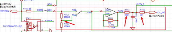
(1) DC power output:

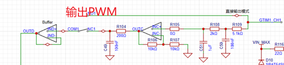
(2) PWM output:
The above are the problems and solutions that I can think of that may occur during soldering and debugging. I hope they can help everyone. If you have any problems that cannot be solved by the above approach, you can also leave a comment and we can solve them together.
Since my writing skills are limited, errors and omissions are inevitable. If you have any questions, please feel free to discuss them in the comments section so we can all improve together.
PDF_Replica Multifunctional Test Pen.zip
Altium_Replica Multifunctional Test Pen.zip
PADS_Replica Multifunctional Test Pen.zip
BOM_Replica Multifunctional Test Pen.xlsx
97215
electronic


 To improve the torque during compression, we used a lead screw + stepper motor to drive the trash compression device.
  :
:  To ensure stable chip power supply voltage, we selected the LM1117 LDO voltage regulator chip for the 5V to 3.3V step-down solution, resulting in lower ripple.
 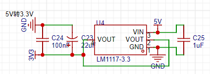 For chip programming, we chose the CH549G chip as the embedded DAP-Link, allowing direct programming via a Type-C data cable; while retaining the traditional SWD four-wire interface for use with a wireless programmer. The overall
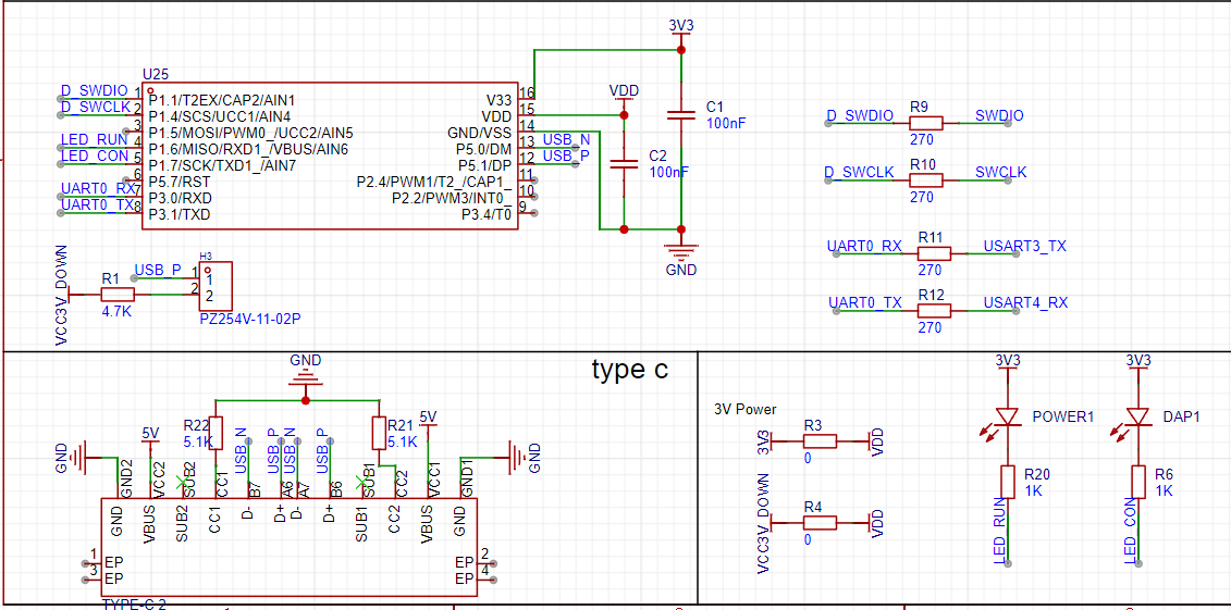


 京公网安备 11010802033920号

 2SC3839KP


