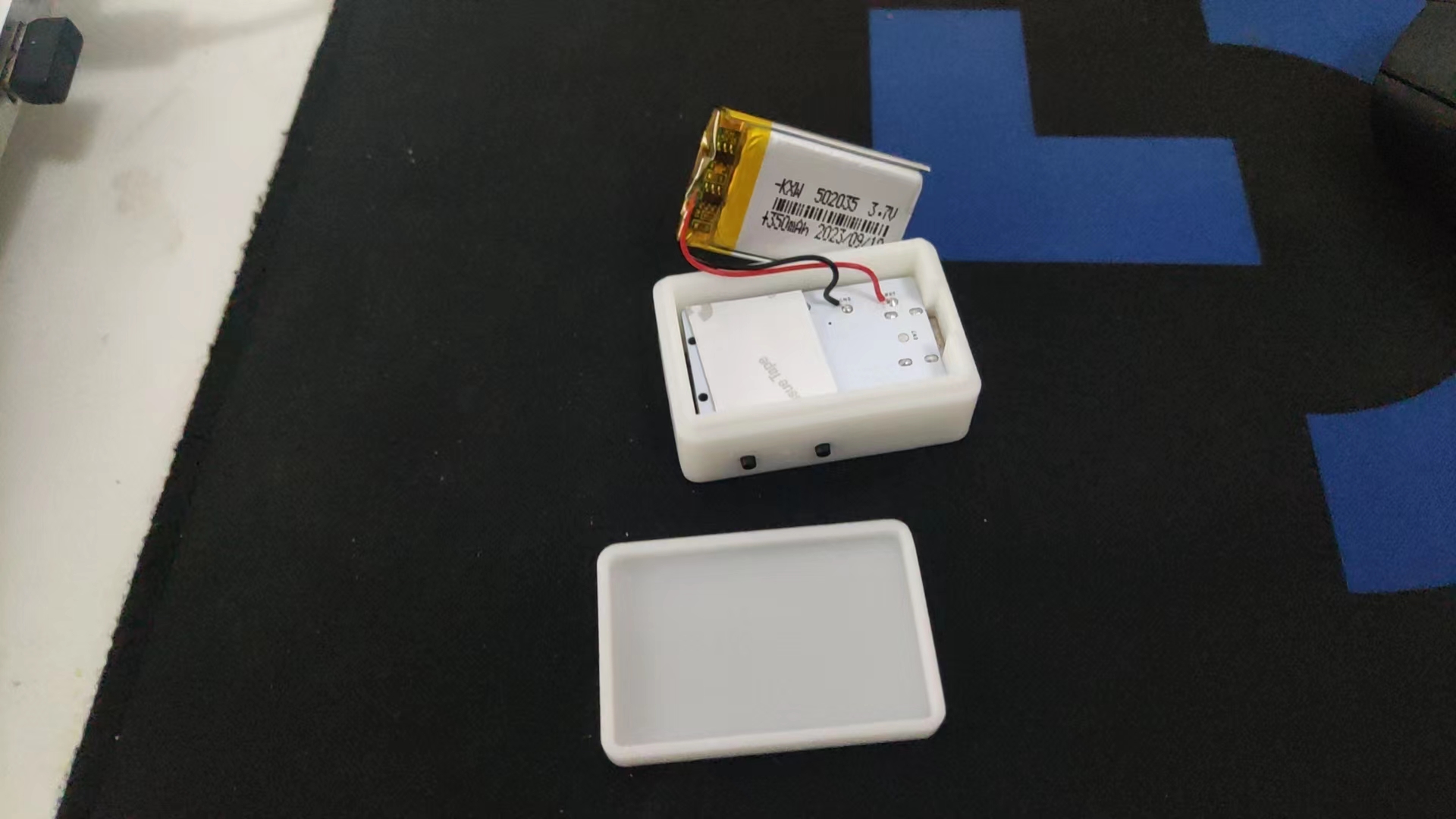
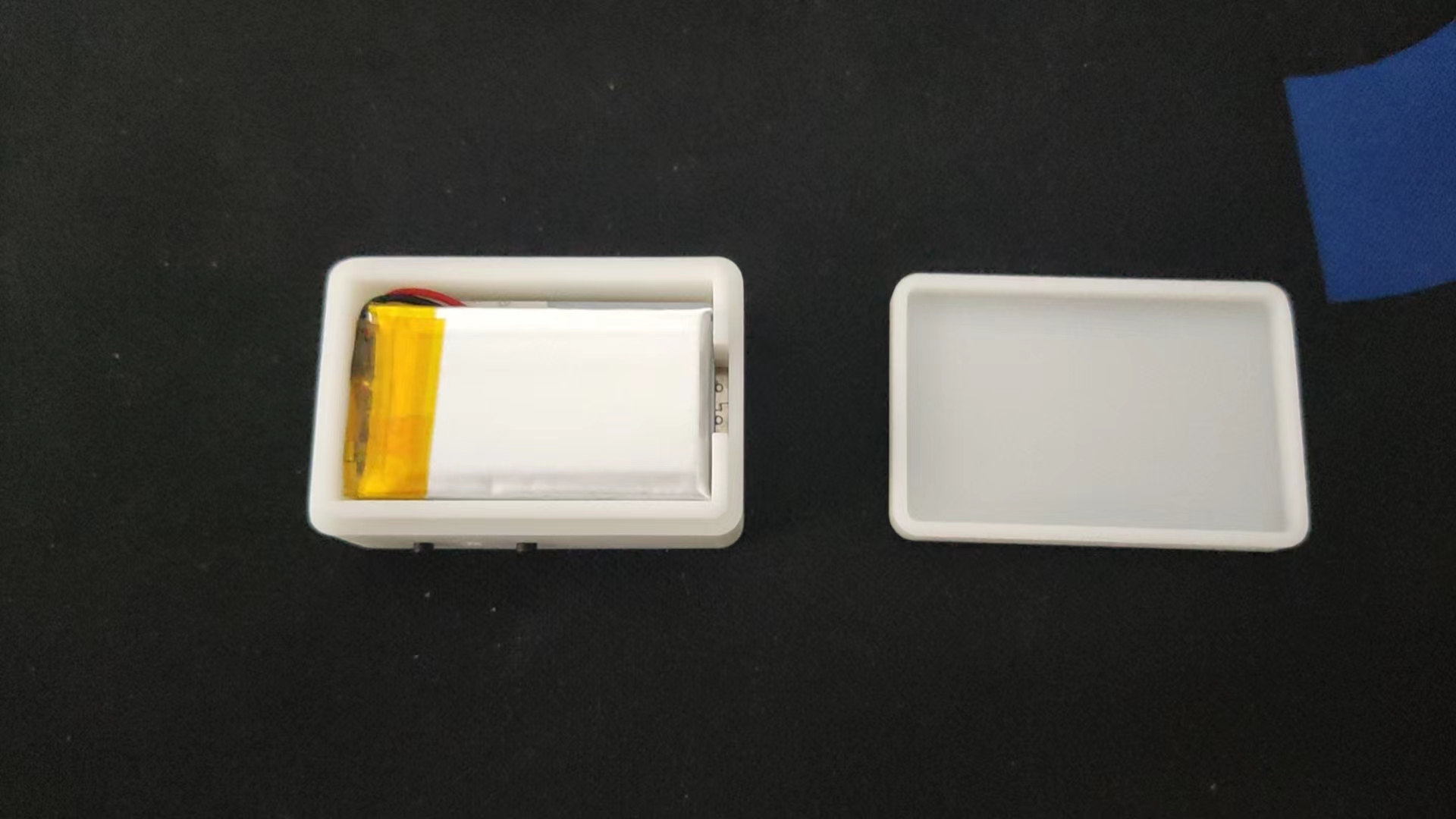
The radio uses a TP4059 to charge the lithium battery and an XC6206P332MR for step-down power. It features a headphone jack with a switch for automatic power-on when headphones are plugged in. The 320mAh lithium battery provides over 10 hours of battery life.
3D casing instructions: It fits a 502035 polymer lithium battery perfectly. Buttons must be soldered during casing assembly; otherwise, they won't fit.
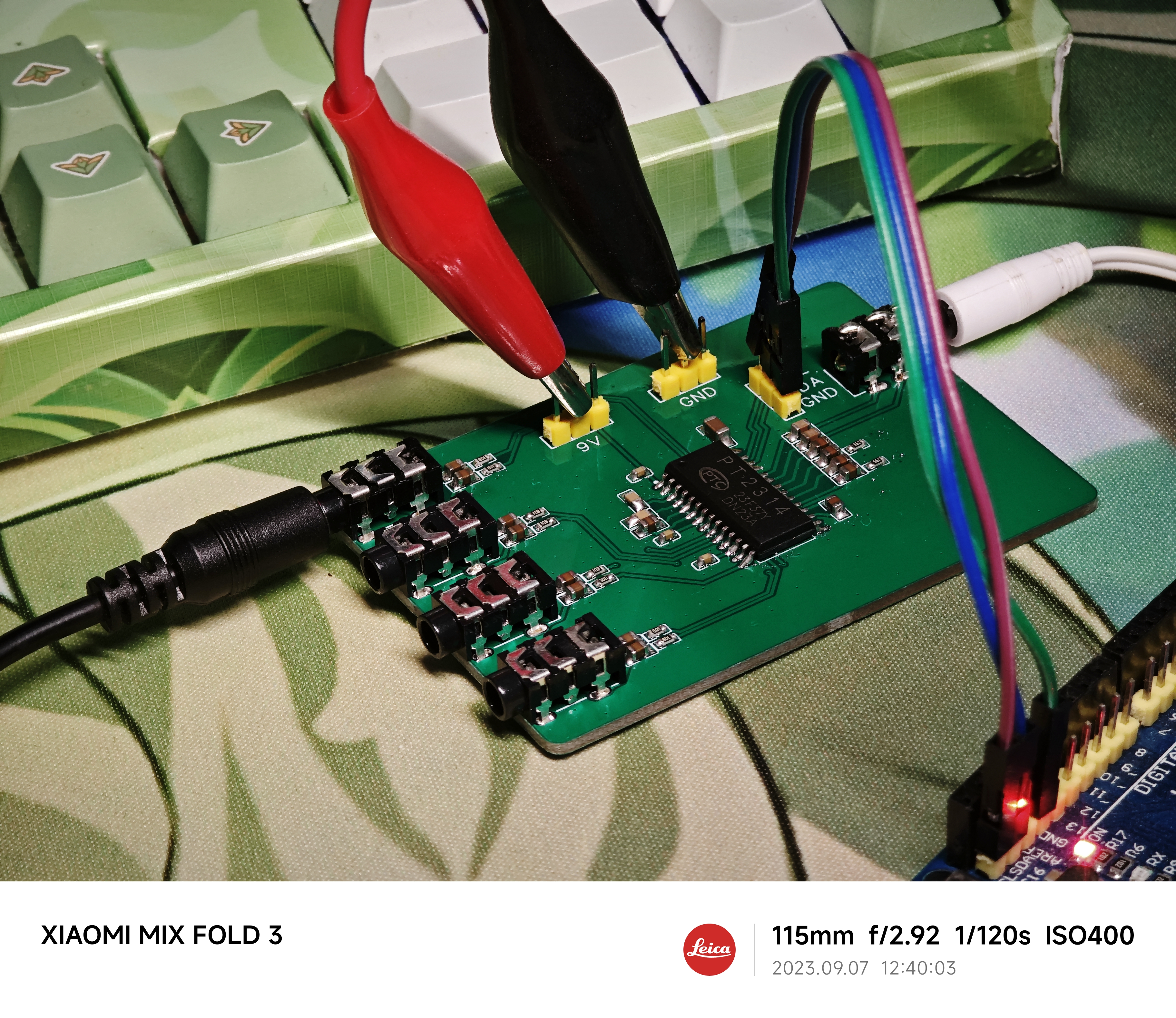
PT2314 4-Channel Audio Electronic Switcher -
1. Introduction:
The PT2314 is an IIC-controlled 4-channel analog audio electronic switcher with volume control.
It has a 9V power supply, which is somewhat inconvenient; a 5V boost circuit and microcontroller control can be added
. 2. Code:
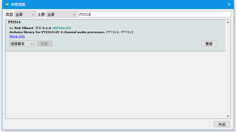
An existing library is available on the Arduino platform and can be used directly.
`pt.setChannel()` sets the switching channel;
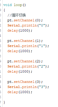
here, the volume is set.

PT2314 pdf, PT2314 Description, PT2314 ...pdf
PT2314_demo.zip
PDF_Audio 1-to-4 Electronic Switcher - PT2314.zip
Altium Audio 1-to-4 Electronic Switcher - PT2314.zip
PADS Audio 1-to-4 Electronic Switcher - PT2314.zip
BOM_Audio 1-to-4 Electronic Switcher - PT2314.xlsx
97337
310 heated bed, 220V aluminum substrate heating, 3D printing /tt/gugubot
Suitable for modifying 310 heated beds (240mm hole spacing) with 220V aluminum substrate heated beds, such as those used in DIY 3D printers like Gugubot, Dayu TT, and Dayu CC.
This is suitable for modifying 310 heated beds (240mm hole spacing), such as DIY 3D printers like those from Gugubot, Dayu TT, and Dayu CC. These printers, in order to control costs, all use 24V DC heated beds, resulting in very slow temperature rise, which can be quite frustrating for impatient users. 220V silicone heating pads truly offer superior heating performance; this open-source aluminum substrate heating pad completely outperforms silicone heating pads.
Each aluminum substrate has a trace length of 9.2m and a thickness of 0.035mm (1 ounce). Nine aluminum substrates are connected in series to a 220V power supply. Theoretical and measured power: [
Table showing trace width , resistance
per substrate,
theoretical power (9 substrates in
series), measured power (9 substrates in series)]
0.5mm
10 ohms
584
541
0.6mm
7.7 ohms
701
649
0.65mm
6.7 ohms
759
703
0.7mm
6.3 ohms
818
757

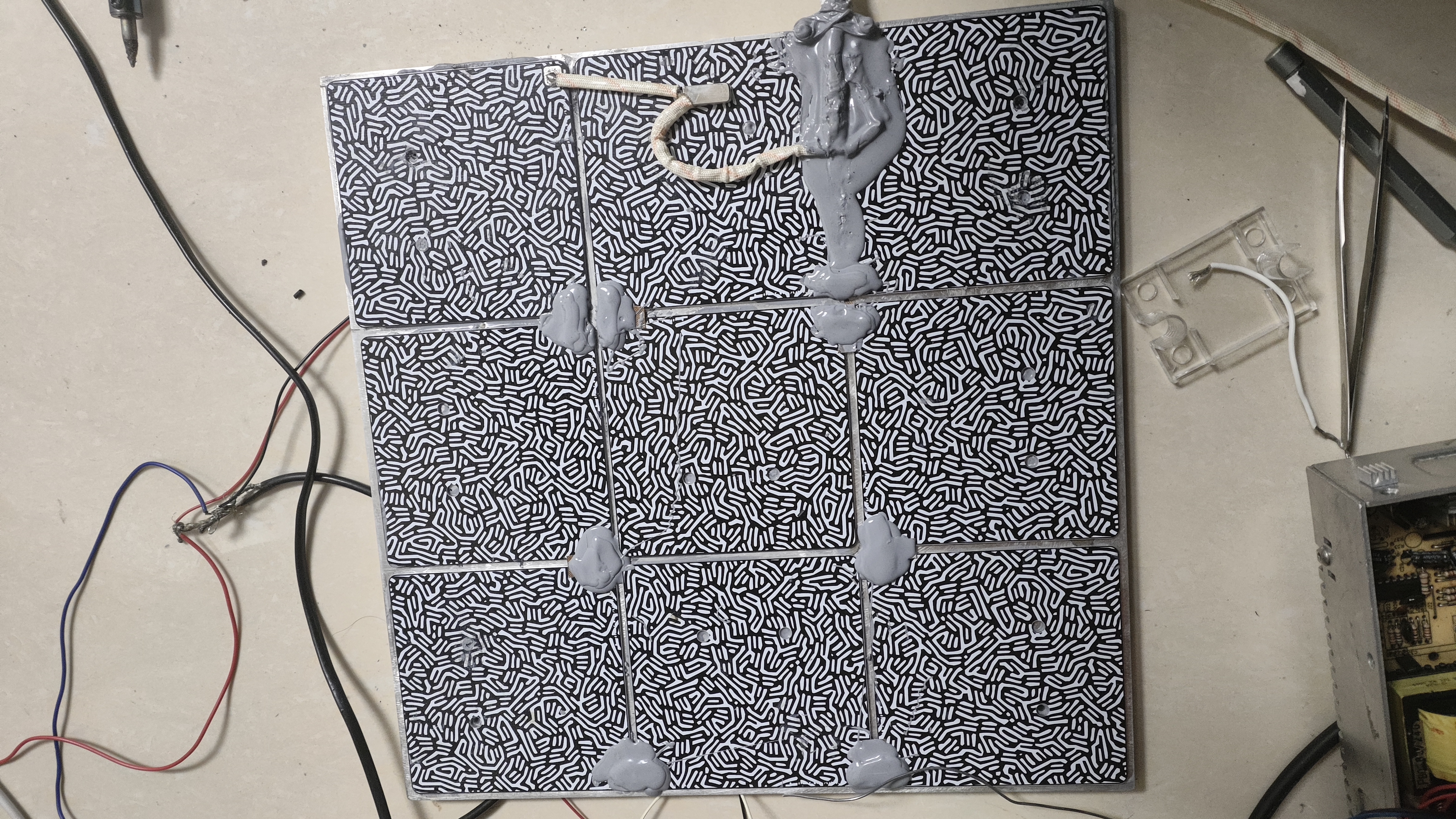
All nine substrates must be connected in series and properly insulated before connecting to the 220V power supply.
The connection method is shown in the diagram below. Ensure proper insulation and cover exposed solder joints with thermally conductive silicone (two tubes are sufficient).
Similarly, use thermally conductive silicone to attach the aluminum substrates and heated bed to the positions shown in the diagram below. (The heated bed can be a previous 24V heated bed, or you can buy a 310*310*8 aluminum plate and drill 240*240mm holes yourself; the cost is around 70).

The PCB includes pads for a 100k thermistor, allowing direct soldering of a 0603 thermistor
for 220V connection. This can be connected in series with a normally closed 120°C temperature switch to prevent overheating and potential fires.

Tested and proven stable and reliable with impressive temperature rise. 0.6mm trace width is recommended (this is the default PCB and PCB design file). Two types of PCBs are available; you can get 5 of each for free (the ones with screw holes are convenient for mounting on a heated bed).
**Important:** Ensure proper insulation and implement leakage protection measures!
ProProject_310 heated bed 220V aluminum substrate heating, 3D printing_tt_gugubot_2023-11-05.epro
Gerber_No Pre-drilled Holes_2023-11-05 0.6mm Line Width.zip
Gerber_Pre-drilled Screw Hole Positions_2023-11-05 0.6mm Line Width.zip
Hilbert curve (without chamfer).dwg
PDF_310 heated bed, 220V aluminum substrate heating, 3D printing - tt-gugubot.zip
Altium 310 heated bed, 220V aluminum substrate heating, 3D printing_tt_gugubot.zip
PADS_310 heated bed 220V aluminum substrate heating, 3D printing_tt_gugubot.zip
97338
esp32s3_clock
ESP32S3 Watch Screen Development Board V1
It's very thick, very thick, very thick!!
This is a test version; it's not recommended to install it.
PDF_esp32s3_clock.zip
Altium_esp32s3_clock.zip
PADS_esp32s3_clock.zip
BOM_esp32s3_clock.xlsx
97339
CH334R_UBS2.0
Based on the Chinheng CH334R USB 2.0 four-port USB hub control chip, plus the SY6280 programmable current limiting chip, the computer power supply is protected from overcurrent and short circuits.
Problem Description:
Most commercially available hubs are essentially pre-installed with a USB-A or Type-C cable, which significantly hinders their functionality, limiting their placement to very close to computer ports. My goal is to create a hub that can be placed anywhere I want, provided there's a long enough cable.
The desired functionality includes:
Type-C input ,
one Type-C female connector to four USB-A female connectors
, overcurrent and short-circuit protection (programmable current limiting settings),
power indicator
, and a beautifully designed, color-screened shell .
The shell design
uses a three-layer structure with a 3D-printed outer casing to maximize the beauty of the color screen printing. The top and bottom panels are transparent, with a color-screened PCB sandwiched in between, and finally covered by the 3D-printed shell. The main structural components, input and output structures, were exported from EDA professional software (the shell wasn't fully exported during verification due to the small computer). The main drawings are of the top and bottom panels and the shell. You can directly use "shell.STL" and "assembly.SLDASM" for their assembly. You can see the final effect; download the compressed file if you want to modify it. You can add patterns and various colors to the panel yourself. Remember to adjust the transparency so that the colored silkscreen printing inside isn't completely covered, losing its bright and shiny appearance and being buried in the casing and panel.

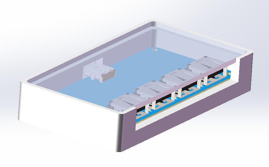
The photos of the colored silkscreen printing can be changed to your liking. As the saying goes, USB 2.0 generally works as long as it's connected, but I've opted for a ground plane enclosure because it's colored silkscreen printing. Since it's inside the casing, both sides need to be exposed so you can see both sides. To accommodate four USB-A ports and a small, non-compressed colored silkscreen printing sheet, the board is designed to be quite spacious. All resistors and capacitors use 0805 packages for easy soldering (Type-C and chips are slightly more difficult to solder). I forgot to add indicator lights during the PCB fabrication process, so there are no indicator lights in the physical demonstration (indicator lights are added in the actual project).
CH334DS1.PDF
3D-USB2.0.zip
Shell.STL
PDF_CH334R_UBS2.0.zip
Altium_CH334R_UBS2.0.zip
PADS_CH334R_UBS2.0.zip
BOM_CH334R_UBS2.0.xlsx
97340
electronic


 京公网安备 11010802033920号

 HLMP-1521-LW000


