The prototype was taken from a USB hub in the square. I rewired it myself to learn from LCSC EDA, and added a PCB cover to the board.
This control board is designed specifically for the Voron 0.2 3D printer. It mainly controls the AB and Z axes, so only 3 stepper motors are needed. The control board will have more interfaces reserved, which can be expanded to include functions such as filament detection, servo control, and lighting control.
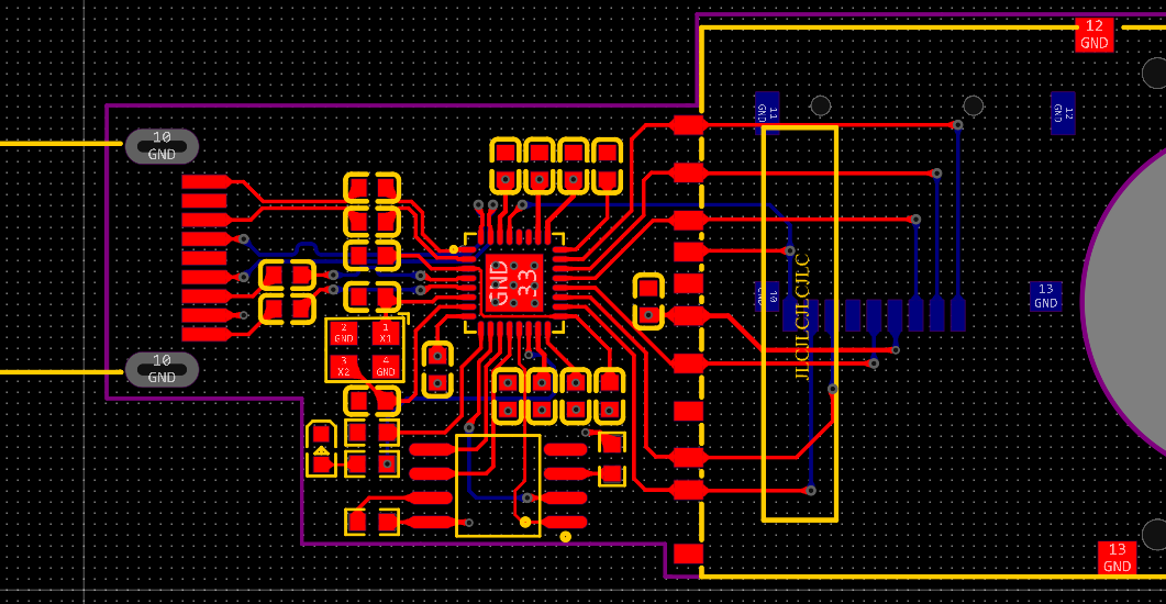
This is a USB 3.0 card reader design based on the GL3224-OIY04 (LCSC part number: C157357) chip. Both TF and SD cards are supported, but only one card can be inserted at a time. Resistors and capacitors are all in 0603 packages for easy soldering.
1. GL3224 Chip Introduction:
The GL3224 is a USB 3.0 card reader controller with a maximum capacity of up to 2TB.
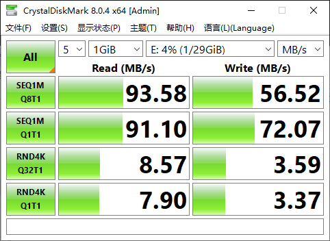
The theoretical read/write speed of the GL3224 is 100MB/s. Actual read/write speeds depend on the quality of the memory card and whether the computer has a USB 3.0 port (blue); USB 2.0 ports are black.
2. Schematic Design Considerations
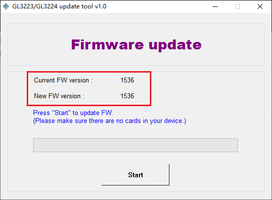
: External Flash: Required because the GL3224 chip's firmware is generally "1532" and needs to be upgraded to the latest version "1536". However, testing showed no significant change in read/write speed after the upgrade, so it can still be used normally without adding external flash.
Flash Model: The commonly used model is W25Q80, with a flash size of 8MB (this is sufficient, but when upgrading firmware, you need to add the flash model to the config.ini file; see the following introduction for details).
External Crystal Oscillator: An external crystal oscillator is recommended for stability. Specifically, it allows for faster and more stable USB drive recognition when plugged into a card reader on the computer.
It's best to connect a 0.1uF capacitor in series between the TX and RX pins (as close to the TX pin as possible) to isolate DC signals and filter out DC components. A TX pin typically generates an AC signal, but the RX pin may not be able to handle or require a DC signal, so the series capacitor filters it out.
GL3224 Pin 16 (RTERM): According to the datasheet, this pin controls the USB signal level. It is recommended to place a 680-ohm, 1% resistor between RTERM and GND.
GL3224 Pin 28 (SD_WP): SD card write protection, connected to GND to enable write. Write protection is not used in this project.
GL3224 Pin 29 (SD_CDZ): SD card detection pin, needs to be connected to the CD pin of the SD card slot and TF card slot.
3. PCB Routing Precautions:
Place filter capacitors close to the power supply.
Differential traces: D+ and D-, TX and RX.

4. Firmware Upgrade Method:
Upgrading the GL3224 firmware to version 1536 requires an external flash chip.
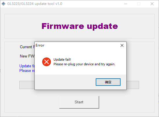
The W25Q80 is not listed in config.ini; you need to add the flash model to this file yourself. The attached file has already been added and can be used directly without modification. If using other flash models, you can refer to the following modifications.

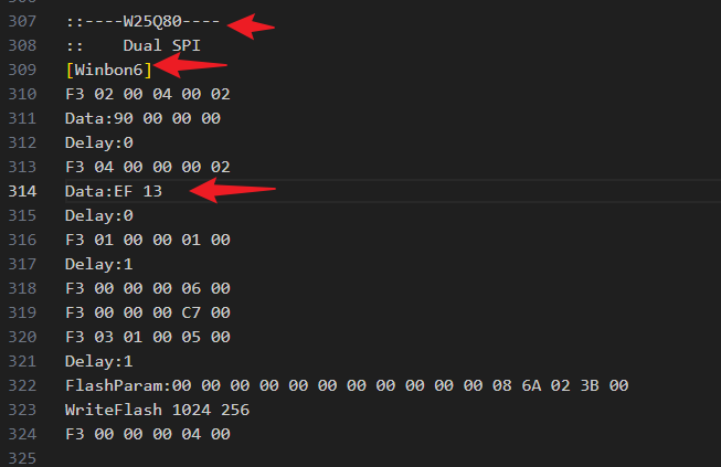
The third line indicates the 6th chip supported by Winbond; the number can be changed, but cannot be repeated. The eighth line is crucial; it describes the address ID of the W25Q16 device, which is a target address for access. If it's incorrect, the other party will not respond. This address is mentioned in section 10.2.1 of its chip manual. For example, it's EF 13 for W25Q80, EF 15 for W25Q32, and EF 14 for W25Q16. The rest can be written according to the other Winbond chips. The GD25Q16 follows a similar principle; first, determine its target address, which is C8 14 according to the chip manual, while C8 12 for GD25Q40.
If the flash model is not added correctly, the following error will occur during the upgrade:
The message after a correct upgrade:
5. Physical testing

uses CrystalDiskMark for read/write speed tests:
File reading test from USB flash drive:

CrystalDiskMark8.0.4c.rar
GL3224 update tool v1.0.zip
GL3224 Datasheet.pdf
PDF_GL3224 USB3.0 Card Reader.zip
Altium_GL3224 USB3.0 Card Reader.zip
PADS_GL3224 USB3.0 Card Reader.zip
97365
3D printer hot end hub board Big Fish TT Big Fish CC
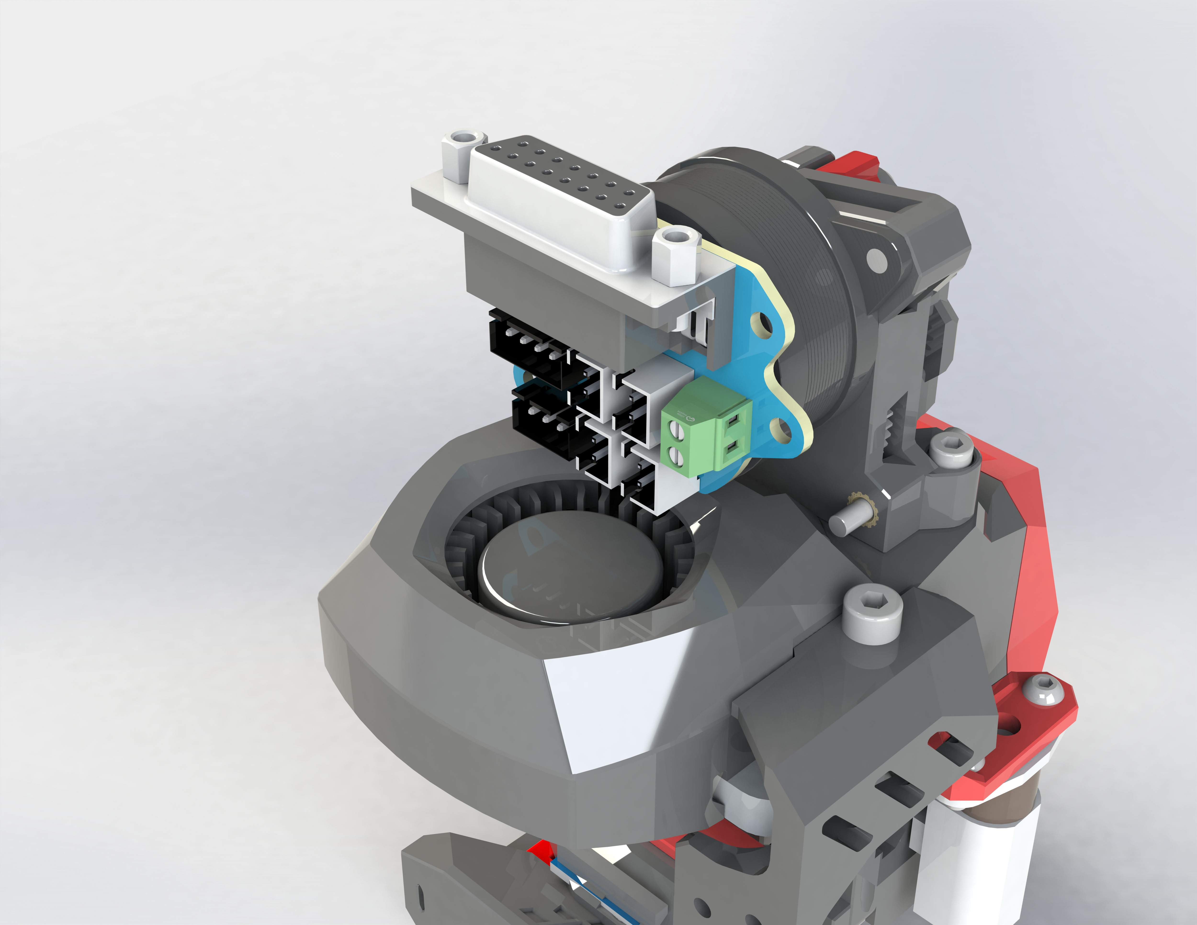
This hot-end hub is suitable for 3D printers such as the BigFish TT and BigFish CC, and can be fixed behind 36-motor or 42-step motors for easy wiring. It uses a screw-mounted D-Sub interface for improved connection reliability.
This hot-end hub board is suitable for 3D printers such as the Dayu TT and Dayu CC, and can be fixed behind 36 or 42 stepper motors for easy wiring. It uses a D-Sub interface with bolt-on mounting for improved connection reliability.
(20231101: Updated FFC cable version
, referencing the Dayu CC 3D Printing Hub Board - JLCPCB EDA Open Source Hardware Platform (oshwhub.com) design, using a D-Sub interface with built-in bolt mounting. Wiring has been optimized to reduce size, and it can be used with 36 stepper motors.
Includes interfaces:
heating rod,
two fans,
one thermistor,
X limiter,
Z limiter , and
stepper motor
. The heating rod and fans share a common anode, while the X and Z limits share a common ground; pay attention to the silkscreen markings during use.
The Z limiter uses a 3-pin interface for proximity switches or Klicky switches; the thermistor uses two separate pins for easy use with PT100.
The heating rod uses KF128-3.5mm terminals for high current handling; the others use XH2.54 terminals.)
For use, you can directly purchase 1-2m long D-Sub 15P (also called DB15) male-to-male cables; connect the two soldered boards together for use, no additional crimping is required.
The mounting holes include both horizontal and angled options, facilitating the use of M3 copper pillars to fix horizontal 36 motors (such as HGX extruders, Big Fish TT, etc.) and angled 36 motors (such as the rear of Sherpa extruders, FZai extruders). Ensure the D-Sub connector faces upwards, as shown in the image.
[FZai extruder image] [

Big Fish TT image]

[PCB diagram]
PDF_3D Printer Hot End Hub Board Big Fish TT Big Fish CC.zip
Altium 3D Printer Hot End Hub Board (Big Fish TT Big Fish CC.zip)
PADS 3D Printer Hot End Hub Board (Big Fish TT Big Fish CC.zip)
BOM_3D Printer Hot End Hub Board BigFishTT BigFishCC.xlsx
97366
USB-HUB (with dial)
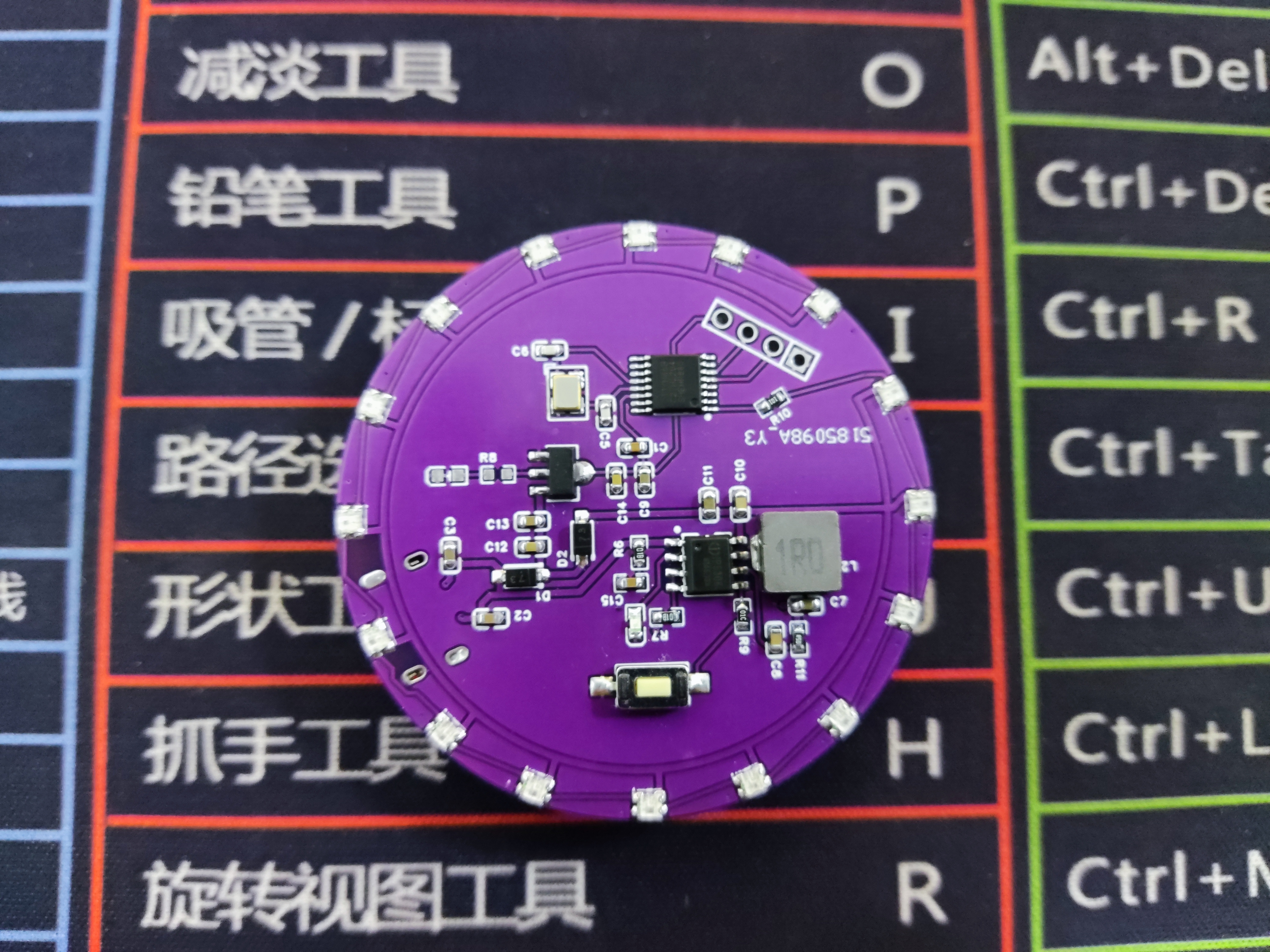
This is a hub splitter with dial functionality. The dial part comes from the basic dial project open-sourced by the developers Shengcai and morempty (with added card reader and TTL versions).
My initial motivation for creating
this was that my computer only had one Thunderbolt 4 port. Although I bought a Xiaomi 5-in-1 docking station (as shown in the picture)

, I still didn't have enough ports because I needed to connect too many USB devices. So, I had the idea of making my own hub splitter. Since I didn't have high speed requirements, I chose the SL2.1A hub chip, which supports USB 2.0. However, I felt that simply making a hub splitter and placing it on my desk would be too monotonous. Rather than investing in the production cost, I thought it would be better to just buy one. So, I wondered if I could expand the functionality of the hub. By chance, while browsing the LCSC open-source hardware platform, I saw the basic Dial project open-sourced by the developer morempty, which immediately attracted me. Since the SL2.1A supports one-to-four, I could use one of the ports to make a dial. I spent some time studying the basic dial, redesigning the board, and verifying it. Thus, this project came about. After obtaining permission from morempty, I open-sourced it. This is my first open-source project.
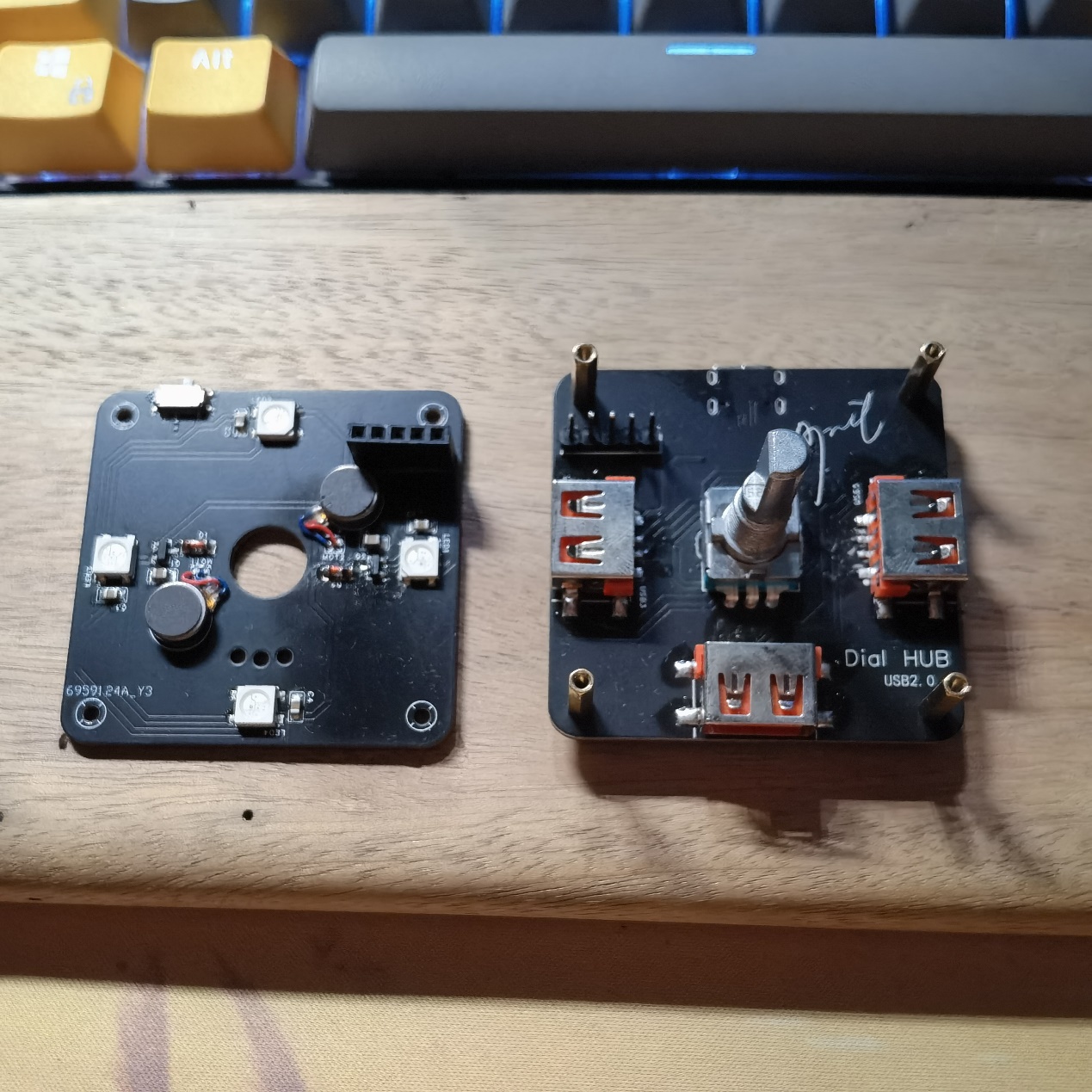
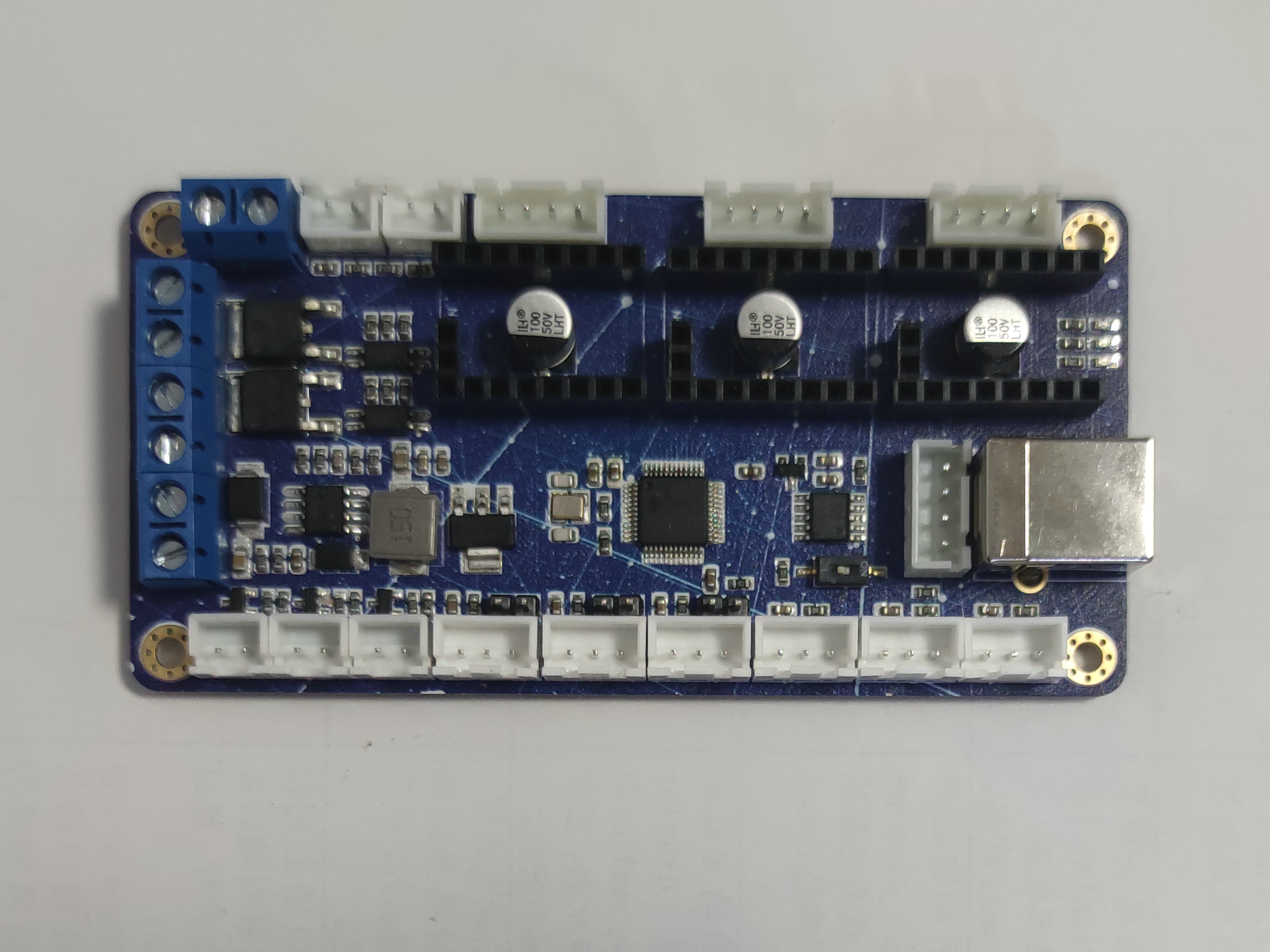
For the motherboard demonstration
, I first created a basic version without being sure if it would be successful, removing the RGB and vibration circuitry from the basic dial (as shown in the image).

Originally, this project would have ended after successful verification, but I encountered a problem—the part highlighted in red in the image. Initially, I planned to design a 3D-printed casing, so I extended the USB-A port slightly. This caused a problem: when soldering the SMD USB-A connector with a soldering iron, it was difficult to position correctly and easily soldered crookedly. Also, without RGB, the 3D-printed casing might not look good. Furthermore, the price of 3D printing is too high for an amateur electronics enthusiast like myself. Therefore, I created a second version, addressing all the aforementioned issues
. The current "Lighting and Vibration Extension" (now renamed "Pro") has optimized the wiring and component placement. Considering that some people may not like lighting and vibration, I have separated the lighting and vibration functions and placed them on the cover plate. They are connected to the motherboard via pin headers and sockets for easy installation and removal (as shown in the picture).
The four corners are fixed with M2*11+3 studs because the pin headers and sockets I purchased fit together exactly 11mm. If you do not plan to use lighting and vibration or use DuPont wires for connection, you can use M2*7~8 studs for fixing. Note that if you use M2*11 studs, it is recommended to purchase an EC11 encoder with a shank length of 20mm. If you use M2*7~8 studs, it is recommended to purchase an EC11 encoder with a shank length of 15mm.
Some points to note during assembly (soldering tools: heating table + soldering iron):
First, the header pins. Most header pins are too long for a 1.6mm PCB, so for flatness, trim them appropriately with pliers or nail clippers before soldering. Second, it's best to solder the header pins onto the cover plate, as the header pins are much harder to trim than the header pins.
Next, the soldering order is recommended: main components of the motherboard (excluding encoder, header pins, and USB-A interface) → components of the cover plate (including header pins) → USB-A interface on the motherboard → header pins and encoder (the header pins need the cover plate's header pins for positioning during soldering). Note that M2*11+3 studs are needed for fixing and positioning during the soldering of the header pins and encoder!
Do not solder 0Ω resistors with the symbol R4 at this time!
Knob Function Description (Default Firmware Version V1.32):
Morempty has described the knob functions in his project, with a fairly detailed description of the dial function. I won't go into too much detail here, but I will provide a link to the "Bare Dial" project later, where you can learn about the functions, flashing methods, and download the firmware. There is also a multimedia mode in the firmware that isn't described in detail, but here's a brief description:
In dial mode, a six-click rotation of the knob enters multimedia mode (you'll see the lights rotating counter-clockwise). Similarly, a six-click rotation in multimedia mode returns to dial mode (the lights rotate clockwise).
In multimedia mode, rotating the knob adjusts the volume, a single click pauses or plays a song, a double click skips to the next track, and a triple click skips to the previous track.
A five-click rotation in multimedia mode adjusts the brightness of the RGB lights or turns them off.
Some EC11 encoders may be reversed in dial mode; in this case, you can enter multimedia mode. In multimedia mode, an eight-click rotation changes the EC11's operating direction, and a six-click rotation returns to dial mode.
Special thanks
to morempty for the open-source hardware materials and 生菜 for the firmware resources.
Regarding third-party sellers (to paraphrase 生菜)
, I have a suggestion: the author hopes buyers will post reviews with pictures in this comment section.
If sellers become profitable enough, could they consider tipping the author to help with future development and improvements?
Of course, selling 5 sets or less is fine; from what I understand, most sellers are students, and I support them recouping some costs.
Perhaps for sales exceeding that, a 2 RMB tip for each set sold could be given to the author? (I would pass this on to 生菜 and morempty, I won't use it myself.) More than that is unnecessary; otherwise, the cost will be passed on to the buyer, reducing competitiveness.
Related Links
: Original Dial Project Link: [Spark Project] Dial - JLCPCB EDA Open Source Hardware Platform (oshwhub.com)
Regarding the BOM,
I feel that some components in the BOM exported by JLCPCB EDA are not accurate. Basically, buying according to the schematic I provided and my description above should not be a problem. There are only a few special ones, which I have listed below. Purchase according to your needs:
M2*4 screws
, M2*4 studs or M2*5 studs,
M2*11+3 studs,
straight-edge USB 2.0 connector, AF female (SMD four-pin full surface mount)
, 1A 8V surface mount, SMD self-resetting fuse,
all surface mount components are packaged in 0805,
vibration motor model is 0827,
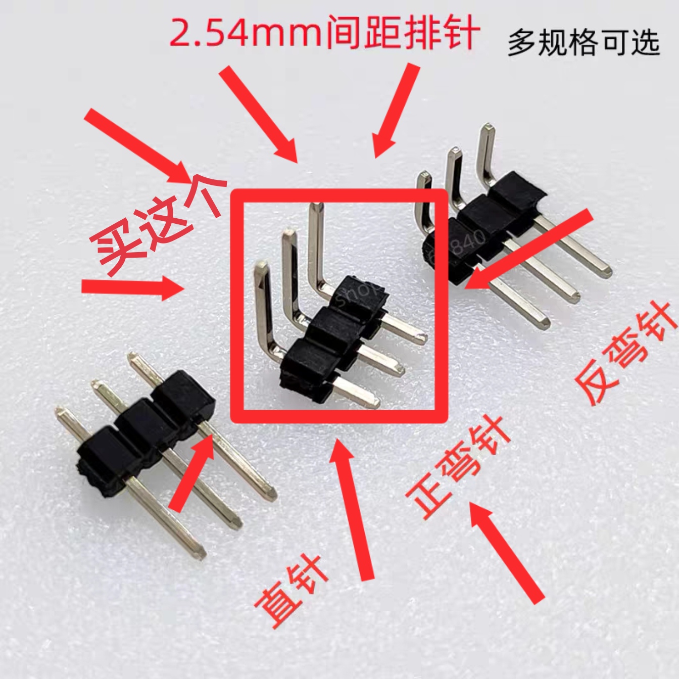
TTL version uses 7-pin positive bend single row header, as shown in the picture.
If you are still unclear, you can send me a private message to ask. If there are many people replicating and there is demand, I will rewrite the BOM.
Version Update
2023.10.20 Update:
Optimized some wiring details;
modified some project names;
added TF card reader version. (Unverified; feedback is welcome if anyone has verified it, and further optimization will be implemented in future versions.)
There were also plans to optimize the cover plate, but considering the difficulty and high cost of sourcing the necessary components, which would unnecessarily increase costs, this plan has been temporarily abandoned.
Update 2023.11.01:
Added a TTL serial port version, based on the CH340C design; (Unverified, feedback is welcome).
Uploaded the 3D model file (.step format) of the universal base, which can be ordered on JLCPCB's 3D Monkey platform. The model is shown in the image.

Uploaded the serial port version driver file; the default is the Windows version. For other versions, please download them from the official website. Driver link: Driver Program - Nanjing Qinheng Microelectronics Co., Ltd. (wch.cn)
V1.1 Version Finished Product Demonstration

and Operation Video.
0a861874cf206218e66692f8701a57a2.mp4
dial base v6.step
CH341SER.EXE
PDF_USB-HUB(with dial).zip
Altium_USB-HUB(with dial).zip
PADS_USB-HUB(with dial).zip
BOM_USB-HUB(with dial).xlsx
97367
C8T6 core board
The STM32F103C8T6 core board features a blue board layout and supports Heze Air32F103CBT6 and STM32F103C8T6/CBT6. It can be flashed with DAP-Link and ST-Link.
An unremarkable core board that uses a TYPE-C interface.
PDF_C8T6 core board.zip
Altium_C8T6 core board.zip
PADS_C8T6 core board.zip
BOM_C8T6 core board.xlsx
97369
TDA1521 Dual-Channel HiFi Amplifier Board
The TDA1521 is a chip with a simple circuit but outstanding sound quality. This project uses the high-current routing design of HiFi amplifiers, single-point grounding, and a large number of high-quality components based on the official circuit. Compared with the previous circuit, its sound quality is a step above! Audiophiles may want to give it a try!
This circuit uses fast recovery diode rectification, Rubycon large-pond filter, ELNA Brown God 2 decoupling capacitors, and Vishay MKP signal coupling capacitors for the signal input, with capacitance approximately double that of the official circuit, resulting in more elastic low frequencies. The output anti-vibration network and 0.1uf power supply filter decoupling film capacitors are all German MKP film capacitors, and the output capacitors are Nichicon FW series... During this routing, the power supply section featured extensive copper plating to reduce ground impedance. The signal section used a floating ground, with separate and independent routing from the audio output ground and anti-vibration network ground, ultimately converging to a single power ground point. Various sizes of mounting holes were designed for each capacitor, allowing easy installation of different package sizes from various brands. I've designed and installed several TDA1521 circuits before, but with this careful design and layout, and by using high-end components, it produced sound immediately after installation. The circuit had no problems, and there was almost no background noise when connected to speakers. Listening with an audio source, it felt like I had a completely new sound system! Not only was the bass more elastic, but it was also very pleasant to listen to for extended periods. Especially when you listen to it late at night when it's quiet, the singer's lip and sibilance sounds and breathing sounds are clearly visible. In short, the details are greatly improved compared to the previous version! My evaluation of this thing is: I don't want to turn it off!
PDF_TDA1521_Dual-channel HiFi audiophile amplifier board.zip
Altium_TDA1521 Dual-Channel HiFi Audiophile Amplifier Board.zip
PADS_TDA1521 Dual-Channel HiFi Audiophile Amplifier Board.zip
BOM_TDA1521_Dual-Channel HiFi Audiophile Amplifier Board.xlsx
97370
electronic
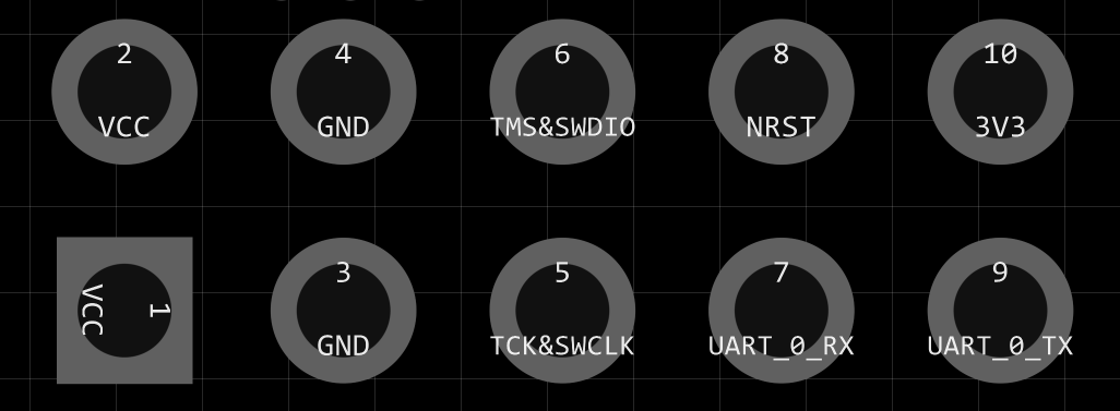 2.2 Pin Descriptions
 Note: Please refer to the schematic diagram for interface pinouts
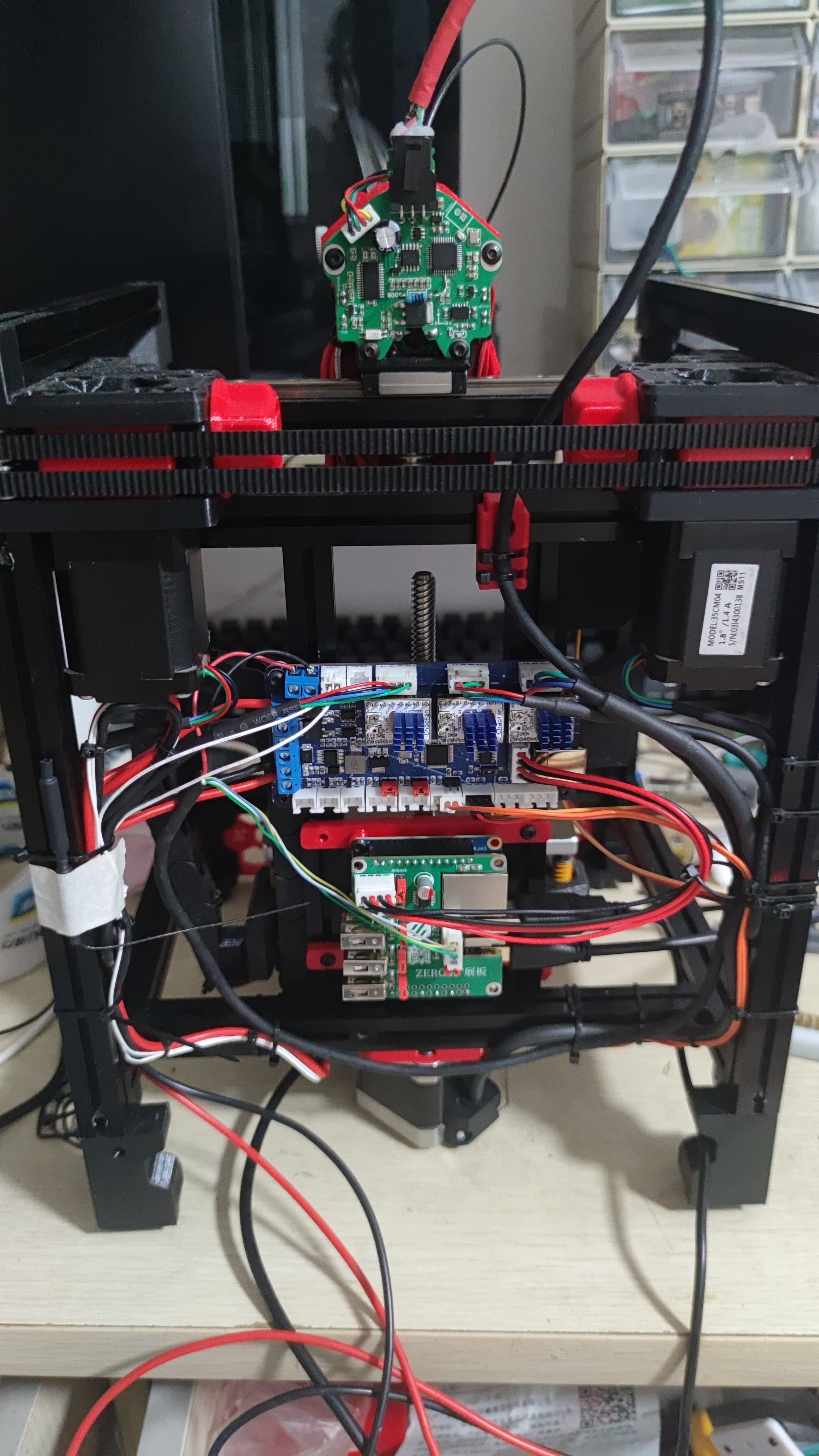


 京公网安备 11010802033920号

 XC2173CD61MR


