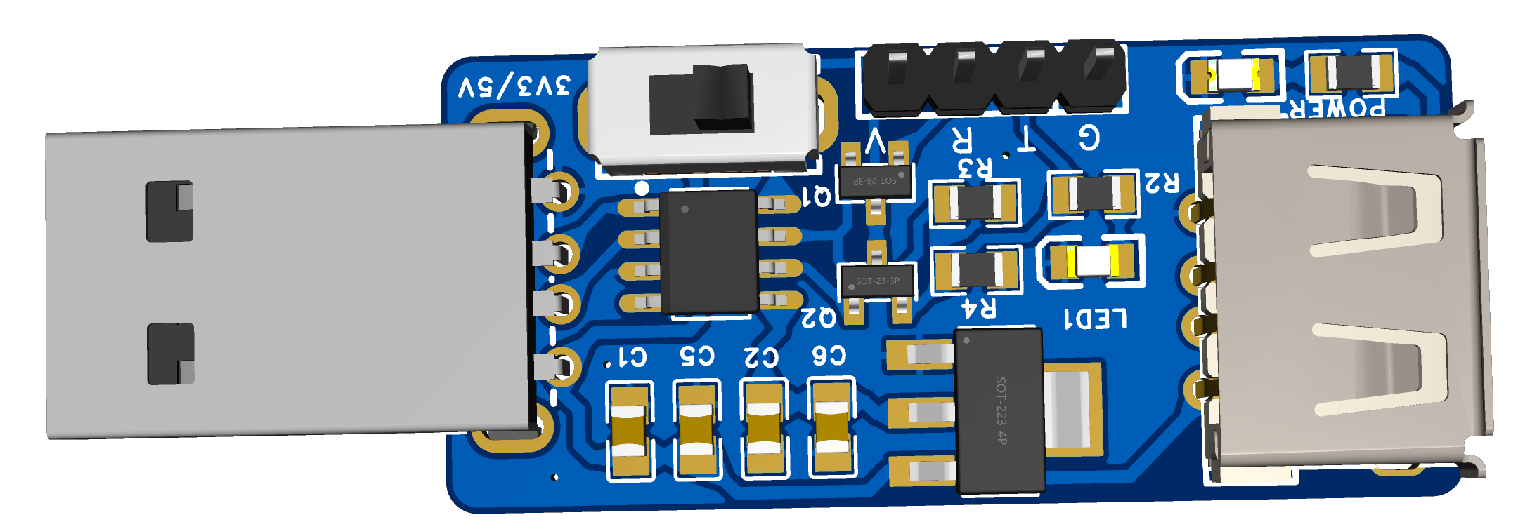
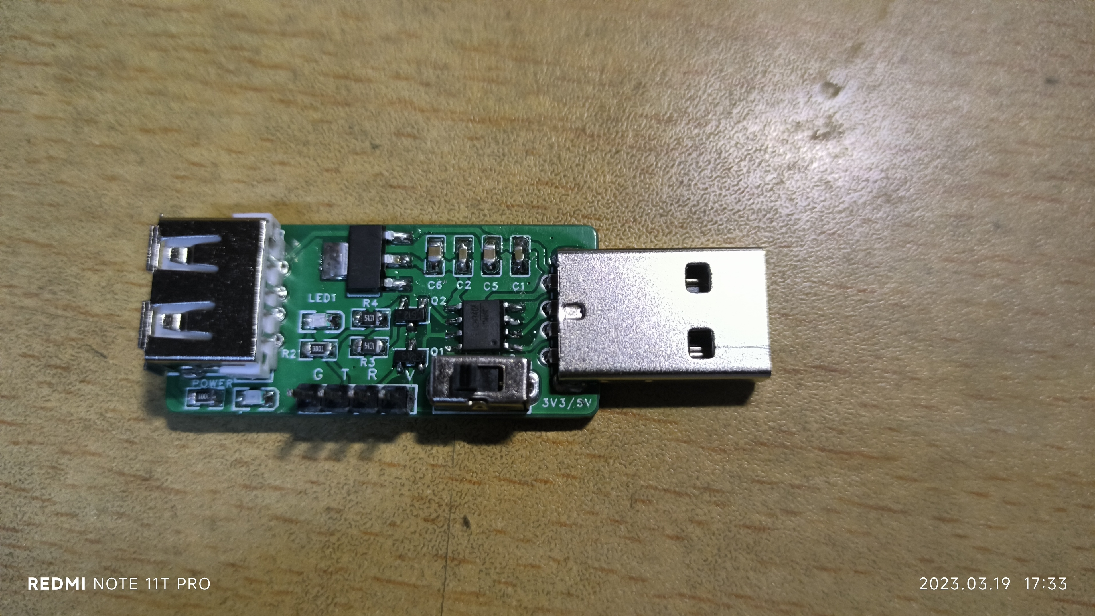
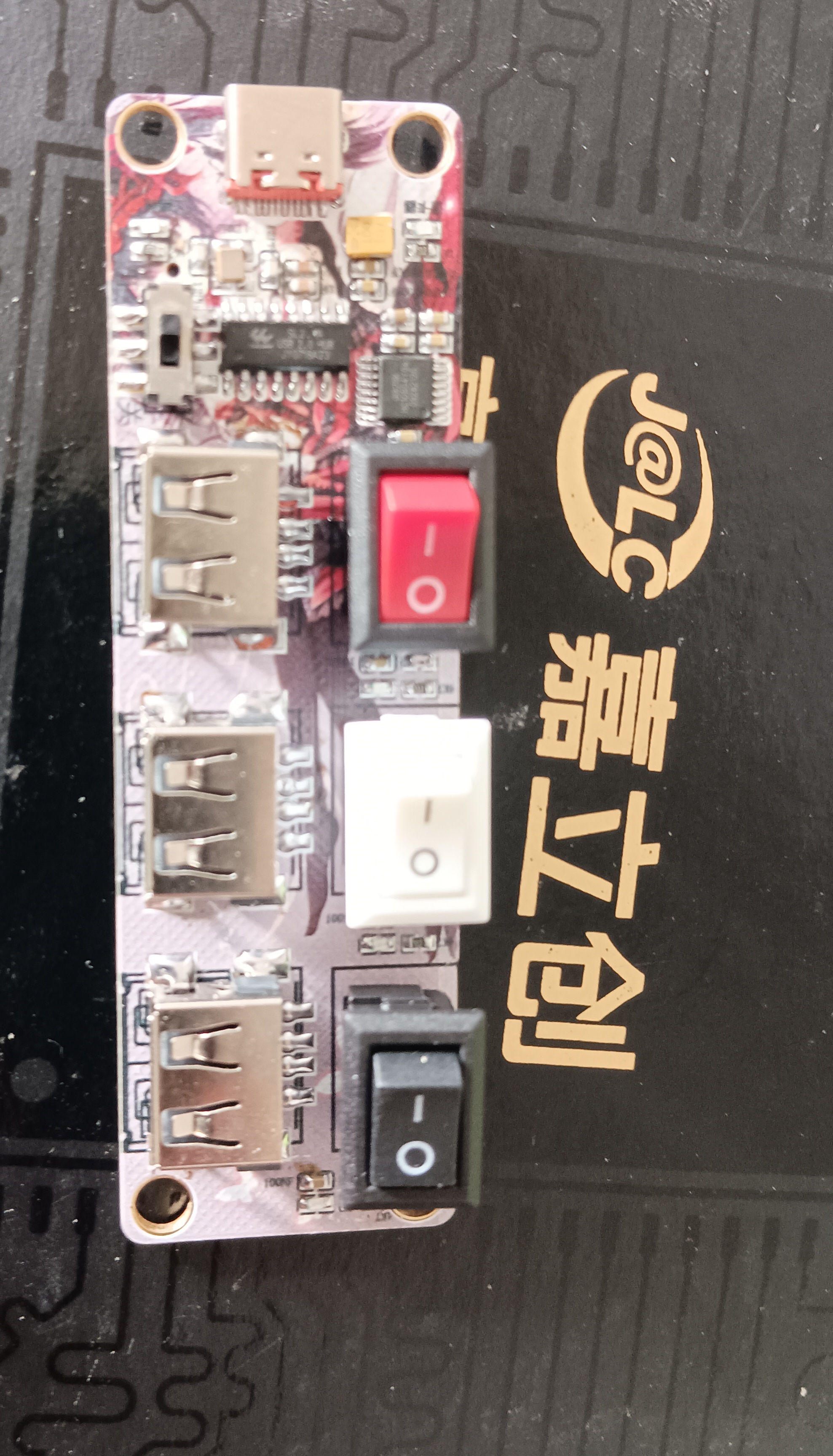
A hub solution based on SL2.1, with color silkscreen printing and an outer casing.
This is an HDMI ambient light controller for TVs and computers, used for controlling HDMI-enabled light strip displays. The product features one HDMI input and one HDMI output interface, and can detect the color at the edges of the video, making the light an extension of the TV screen.
I. Product Introduction
This is an HDMI TV ambient light controller for controlling HDMI-enabled LED strip displays between TVs and computers.
The product features one HDMI input and one HDMI output interface, capable of detecting the color at the edges of the video feed and driving the LED strip around the TV, making the light an extension of the TV screen.
Currently available solutions on the market can be compared as follows:
PC software versions are inexpensive but complex to operate, requiring constant screen recording, raising privacy concerns. There are also compatibility issues with Macs and some Windows computers.
Camera versions, while compatible with smart TVs and inexpensive, still have initial installation difficulties, requiring calibration of the four edges of the screen in the app, resulting in high latency, inaccurate colors, and susceptibility to external light interference.
The HDMI solution is unaffected by external light, has a simple initial installation, low customer training costs, and requires no app or PC software debugging. However, it must use the TV's HDMI input port; smart TVs do not support it.
II. Application Scenarios
When you are immersed in the world of high-definition (HD) video, HDMI video ambient lighting can bring you a completely new visual experience. Whether watching movies, playing games, or enjoying music, HDMI video ambient lighting creates a soothing environment through the interplay of color and light. By connecting your HDMI devices (such as TVs, projectors, or game consoles) and specially designed ambient lighting, you can create an immersive audiovisual atmosphere while watching movies or playing games. HDMI video ambient lighting intelligently adjusts the color, brightness, and dynamic effects of the light according to the image content and colors on the screen, complementing the image and creating a more immersive experience. Imagine watching a thrilling movie, and the HDMI video ambient lighting adjusts the color and brightness of the light according to the plot changes, drawing you into the movie's atmosphere. Or, while playing games, the light changes according to the game scene, enhancing your gaming experience. Furthermore, HDMI video ambient lighting can synchronize with music, responding to the rhythm and melody with vibrant lighting effects, making your musical journey more dynamic and enjoyable. HDMI video ambient lighting provides a completely new immersive audiovisual experience, taking you into a wonderful world of images and music. Whether you're a movie buff, gamer, or music enthusiast, HDMI video ambient lighting offers a unique sensory experience. Let light, images, and music blend seamlessly to create an unforgettable audiovisual feast. Enjoy the endless fun of HDMI video ambient lighting!
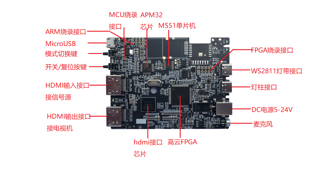
III. Product Overview
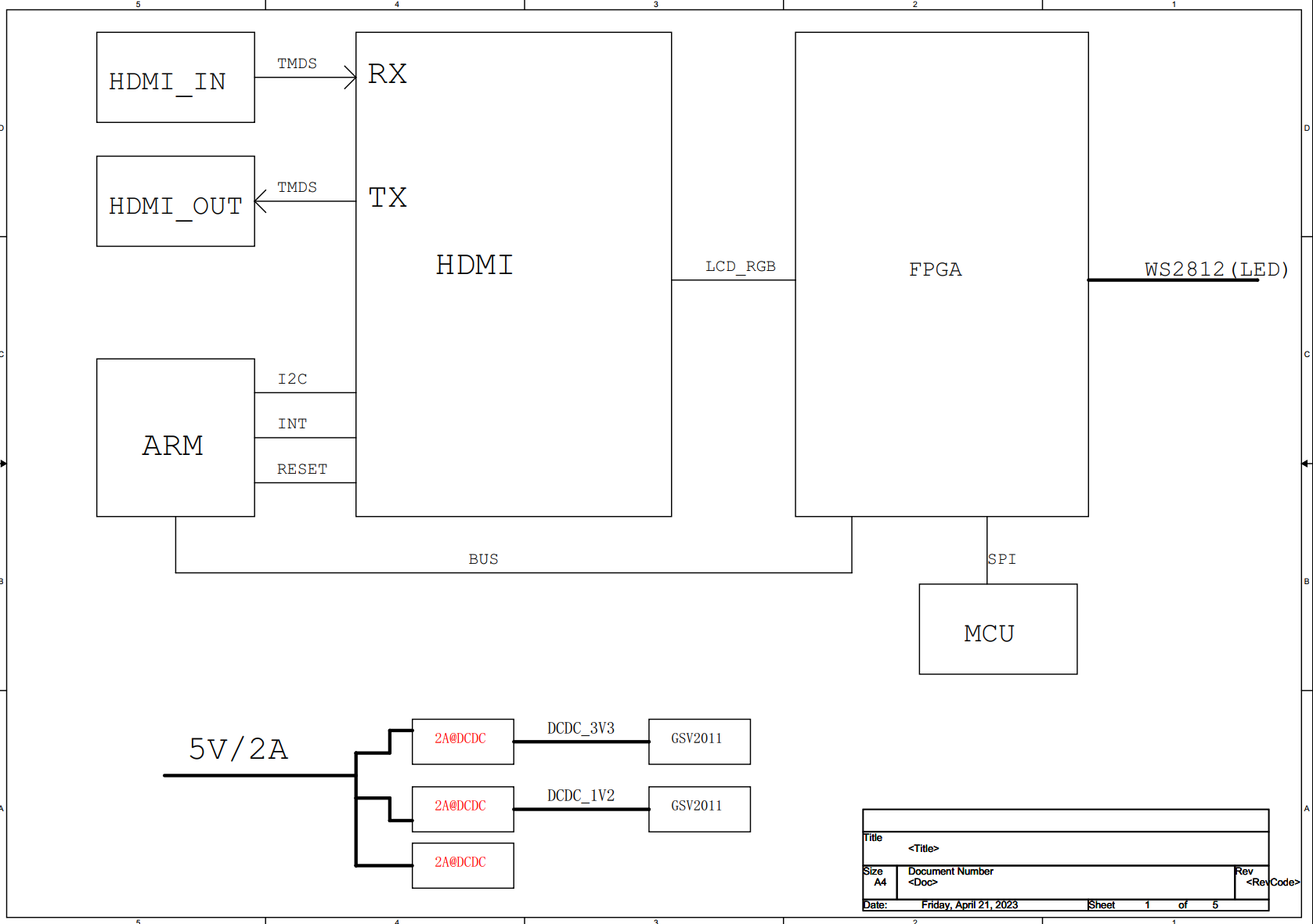
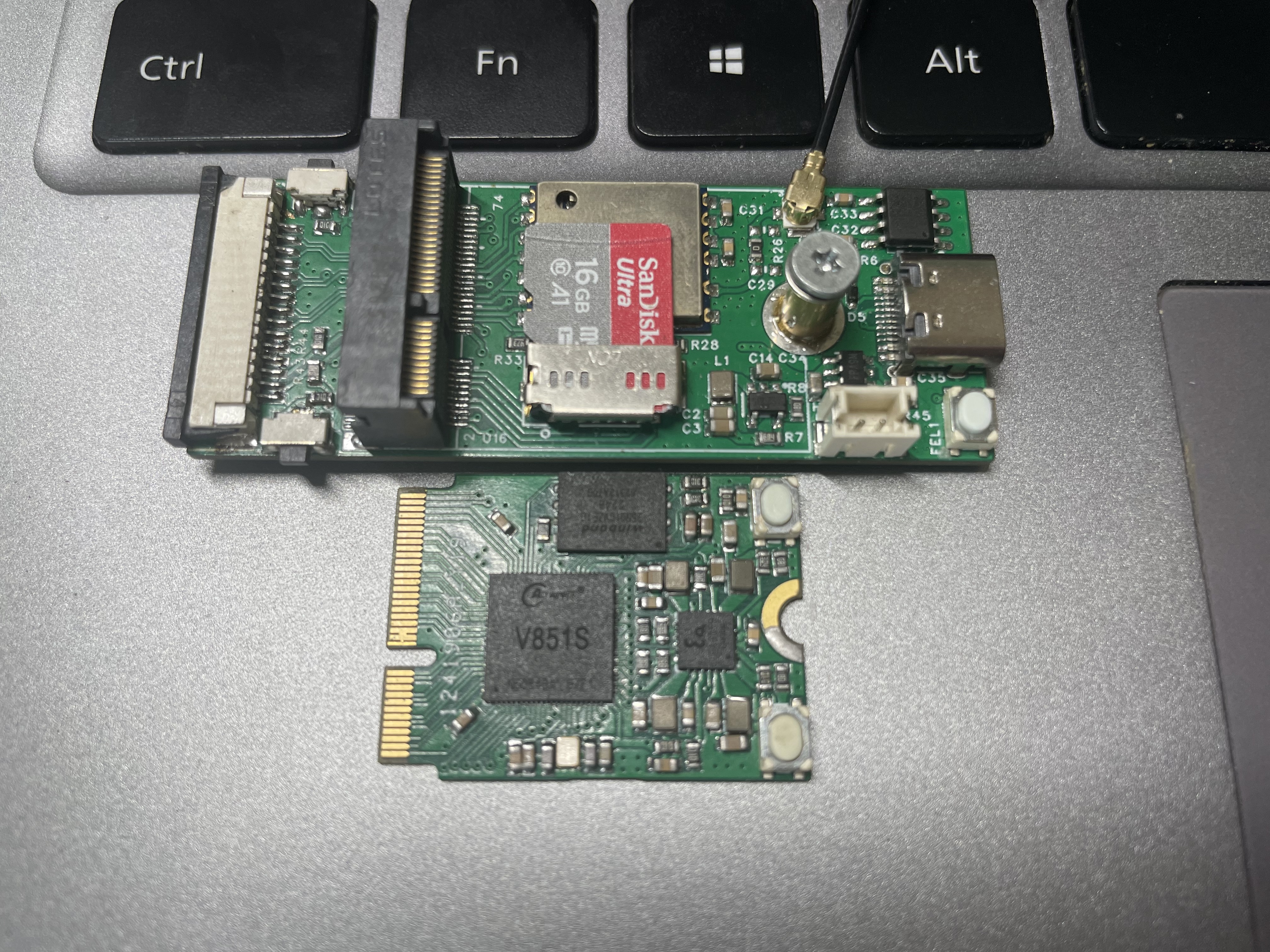
This solution uses all domestically produced chips, with the GSV2011 HDMI transceiver and the Gowin GW1N-UV2LQ100XC6/I5 FPGA as the core processing unit. It has a small resource footprint, using only 2K of logic resources for digital image processing. The specific signal processing flow is as follows:
After the HDMI signal from the computer or set-top box is input through the GSV2011 chip, one signal is looped out through the HDMI to the monitor or TV, while the other signal is decoded by the GSV2011 into a TTL signal format, 24-bit RGB888, which directly enters the FPGA for image processing. This makes the system extremely simple. The STM32 MCU is used to configure the IIC channel of the GSV2011 chip. The RGB signal received by the FPGA is partitioned according to the number of LED strip ICs, and the average RGB brightness of each area is calculated. Finally, the RGB LED strip is driven by the WS2811 controller. The MS51 microcontroller is used to configure and communicate with the FPGA. It has reserved interfaces for Wi-Fi/2.4G modules for external communication, for future upgrades.
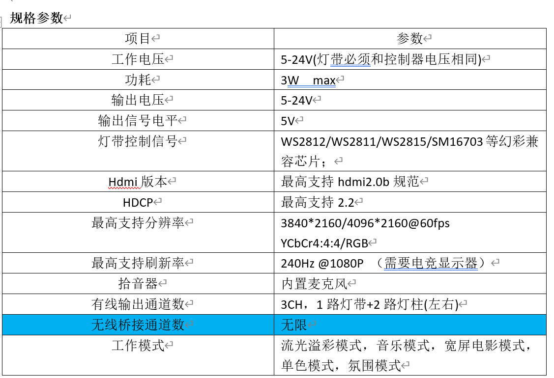
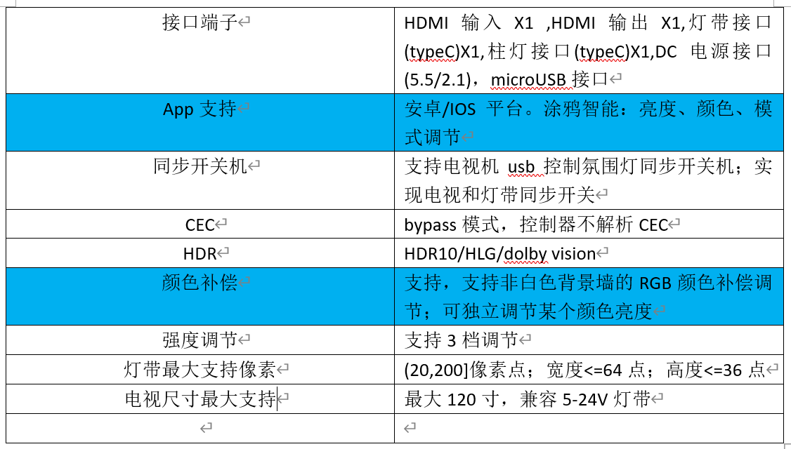
IV. Product Parameters
Product Features (Features not shown on this circuit board are marked in red)
l High cost-performance ratio
l Utilizes FPGA real-time video processing, with extremely low light latency and accurate color capture. More suitable for low-latency applications such as e-sports.
l Supports simultaneous control of standard 5-24V LED strips and light columns;
l Supports wireless bridging of other light fixtures for synchronized control of the entire room's lighting;
l Supports synchronized automatic power on/off for TVs
; l Supports HDR and Dolby Vision
; l Supports HDMI 2.0b protocol, up to 18G_4K 60fps, YCbCr 4:4:4
; l Supports control via the Tuya app
; l Simple installation, no debugging required, works immediately upon power-on
; l Supports Google Alexa voice control;
l Can be installed on computer monitors and 120-inch TVs;
l Immersive experience: video mode, music mode, color wheel mode, multiple built-in scene modes, test mode
. V. Instructions for Use
1. Install the LED strip 1 on the back of the TV, starting from the lower left corner of the back of the TV!!
2. Connect the LED strip cable 2 to the "LED Strip" port on the synchronization box.
3. Connect the synchronization box and the TV's HDMI interface using HDMI cable 3.
4. Connect the synchronization box and the set-top box or game console using HDMI cable 4.
5. Connect the power adapter 5 to power on all devices. The system works normally upon power-on with default settings.
LED strip wiring diagram definition: 1 WS2811 signal.

Light bar wiring diagram definition: 2 WS2811 signals .

Note: This firmware is for a 3-sided LED strip; do not attach the bottom LED strip. It must be attached counter-clockwise from the bottom right corner (when viewing the TV from the front).
Since the control box requires an HDMI signal input, TVs with internet TV cannot synchronize with their internal programs; an external HDMI signal source is required.

VI.
Notes on PCB manufacturing:
1. The PCB is a 4-layer board; please note this.
2. Due to the presence of a BGA chip, it is recommended to use immersion gold plating to avoid unevenness in the soldered board.
3. Impedance control is required for the PCB; please refer to the Gerber file for instructions.
4. This controller can be used with TVs (12V LED strip), computers (5V LED strip), and projectors (24V LED strip). 5. LED Strip Wiring: LED strips must use a color-changing IC, not RGBCW LED strips.
LED Strip Wiring: LED strips require a Type-C adapter cable; the signal line is the CC pin. LED posts require a Type-C adapter cable; the signal line is the D+ and D- pins, two independent channels. Please refer to the schematic diagram.
6. Power Supply: The controller does not have a voltage conversion function. You must use a power adapter with the same voltage as the LED strip and LED posts you use.
7. HDMI cable must be 2.0 specification.
8. MicroUSB is for later synchronization with TV power on/off function; it is not used this time.
9. The attachments include a manual, component reference diagram, some component purchase links, and firmware + burning instructions (use AMO's offline programmer; load the hex file to burn).
Cost breakdown:
GSV2011/1011 chip: approximately 30/25; HDMI 2.0/HDMI 1.4 can be surface-mounted according to requirements.
Gowin FPGA chip: around 13 RMB;
APM32F030C8T6: around 3 RMB;
MS51FC0AE: around 2.5
RMB; PCB: 5 RMB (bulk purchase)
. -------------------------------------------
Total cost of the complete set: approximately 60 RMB (including PCB and SMT). HDMI 1.4 version
LED strip, HDMI cable, power supply (2A). Other items are calculated separately. If using a bare 2812 LED strip for monitors, the total cost should not exceed 100 RMB before tax.
SMT mounting is recommended; the remaining components (DC connector, buttons, microphone) should be hand-soldered.
VII. Test video
reference.
VIII. Latest update:
To be updated .


 ...
...


 京公网安备 11010802033920号

 CHP2010L1422DGT


