This development board was designed for the C8T6 microcontroller and tested using the STM32F103C8T6. It represents
the first self-designed board created by a vocational school student preparing for the college entrance examination.
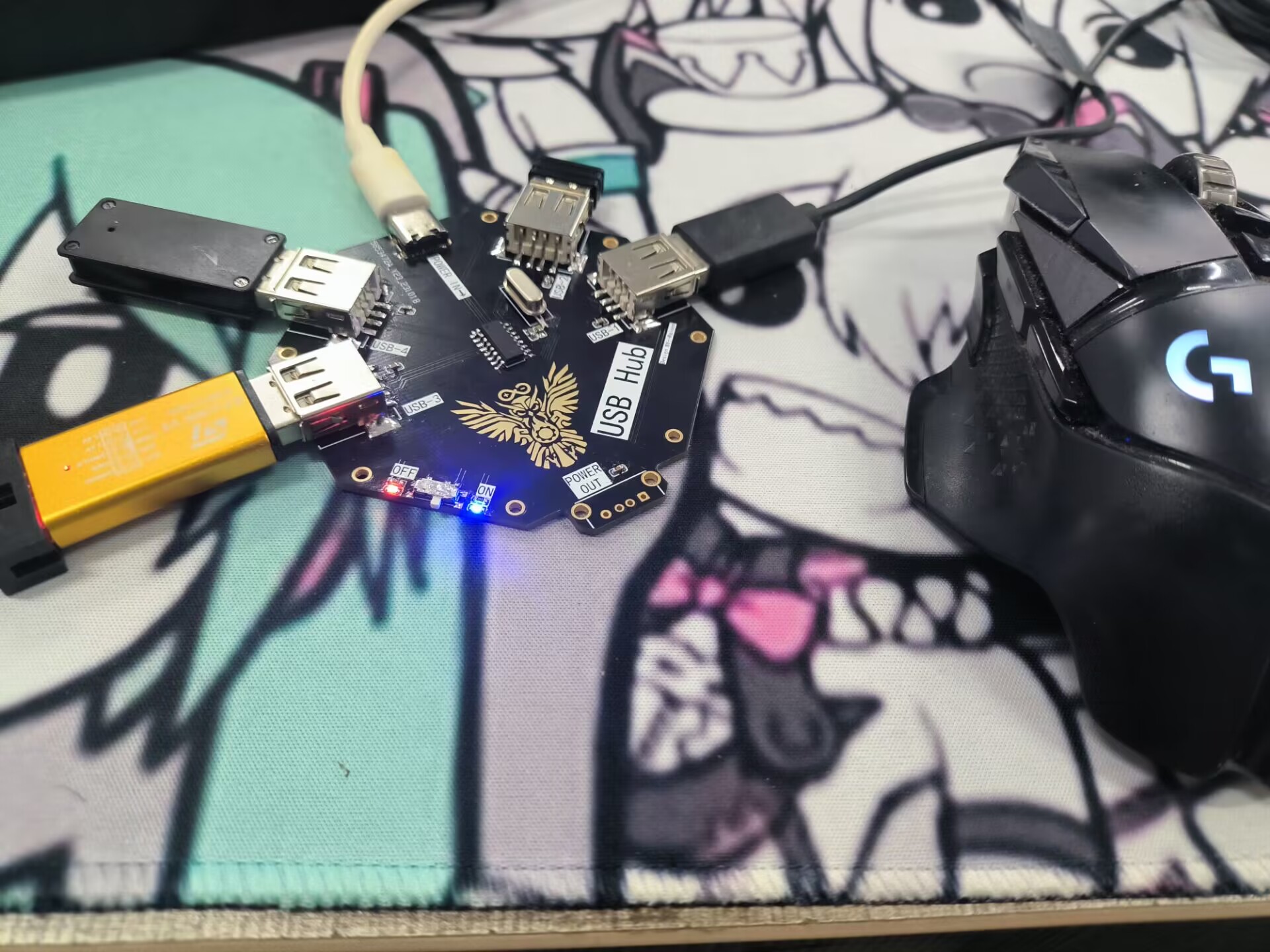
This low-cost USB docking station, based on the SL2.1A design, supports USB 2.0 and is simple to design and solder, making it easy to DIY without the need for programming.
This low-cost USB docking station, based on the SL2.1A design, supports USB 2.0. The circuit design and soldering are simple, making it easy to DIY and requiring no programming.
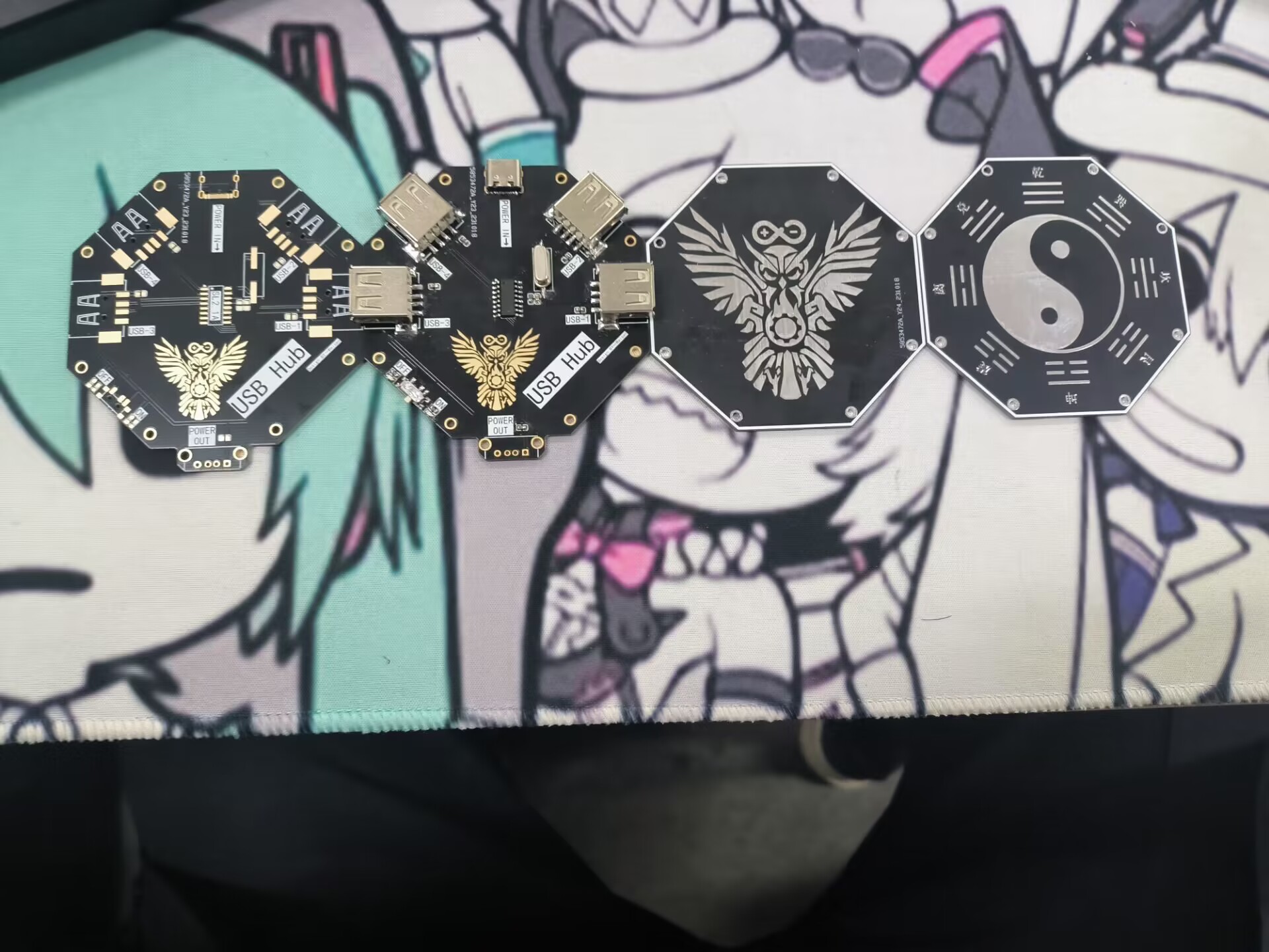
Its shape resembles a yin-yang symbol. It connects to a computer via a Type-C port and supports five Type-A ports, one of which can only be used for power.
The top plate is optional and purely decorative. The top and bottom plates are connected using M2 screws and M2 washers/nuts.
Due to budget constraints, it wasn't printed with color silkscreen (please approve!).
The top and bottom plates (back side) have a large blank area. The back of the bottom plate has no components or traces, and most components are surface-mount with only a few vias. There's ample space for custom images. With a larger budget, a more elaborate design with color silkscreen printing would enhance the effect.
Finished product demonstration.
PDF_SL2.1A Taiji USB Expansion Dock (Verified).zip
Altium_SL2.1A Taichi USB Expansion Dock (Verified).zip
PADS_SL2.1A Taiji USB Expansion Dock (Verified).zip
BOM_SL2.1A Taiji USB Expansion Dock (Verified).xlsx
97430
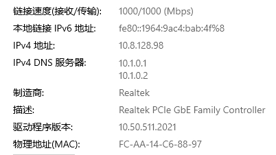
A five-port gigabit switch based on Yutaiwei YT9215S
This is a gigabit, user-friendly switch based on the YT9215S chip. The Ethernet switching chip is the YT9215S from Yutai Microelectronics, and it has 5 Ethernet ports and supports Type-C power delivery.
[Updated 9.12] Fixed incorrect resistor values for the network port.
[Updated 10.26] Updated physical photos
. 0. The schematic diagram and software of this project are for learning and communication purposes only and may not be used for any commercial purposes. Please abide by the relevant open source agreements!
1. I am a beginner, please feel free to give me your guidance.
2. Project Description
This is a gigabit simple switch based on YT9215S. The Ethernet switching chip uses YT9215S from Yutai Microelectronics (theoretically, Pin2Pin is compatible with Realtek RTL8367S, but it cannot boot in practice? Strangely, I couldn't find the problem after checking the datasheet). The interface has 5 Ethernet ports, supports TYPE-C power supply and has reserved DC 12V input


. 3. Tested and working without problems.
4. Configure the resistor
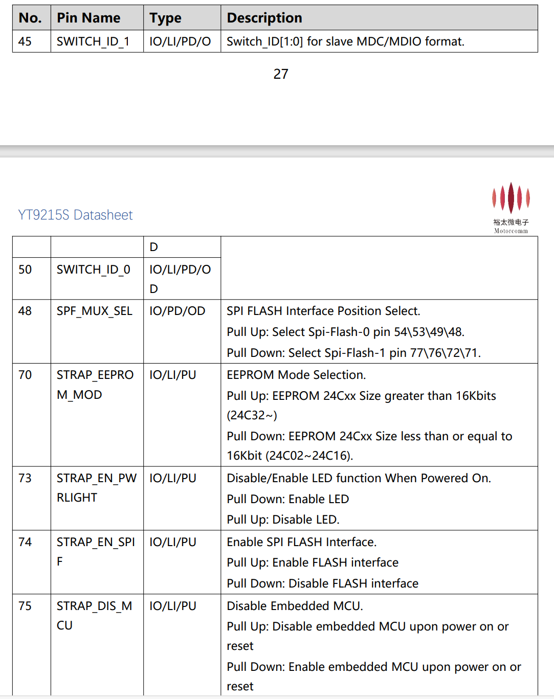

multiplexing pin to read the level when powered on.
5.
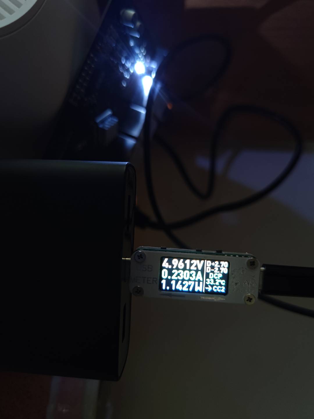

The above figure shows the power consumption and temperature of two ports (with heatsinks). The power consumption of three ports is about 1.6W

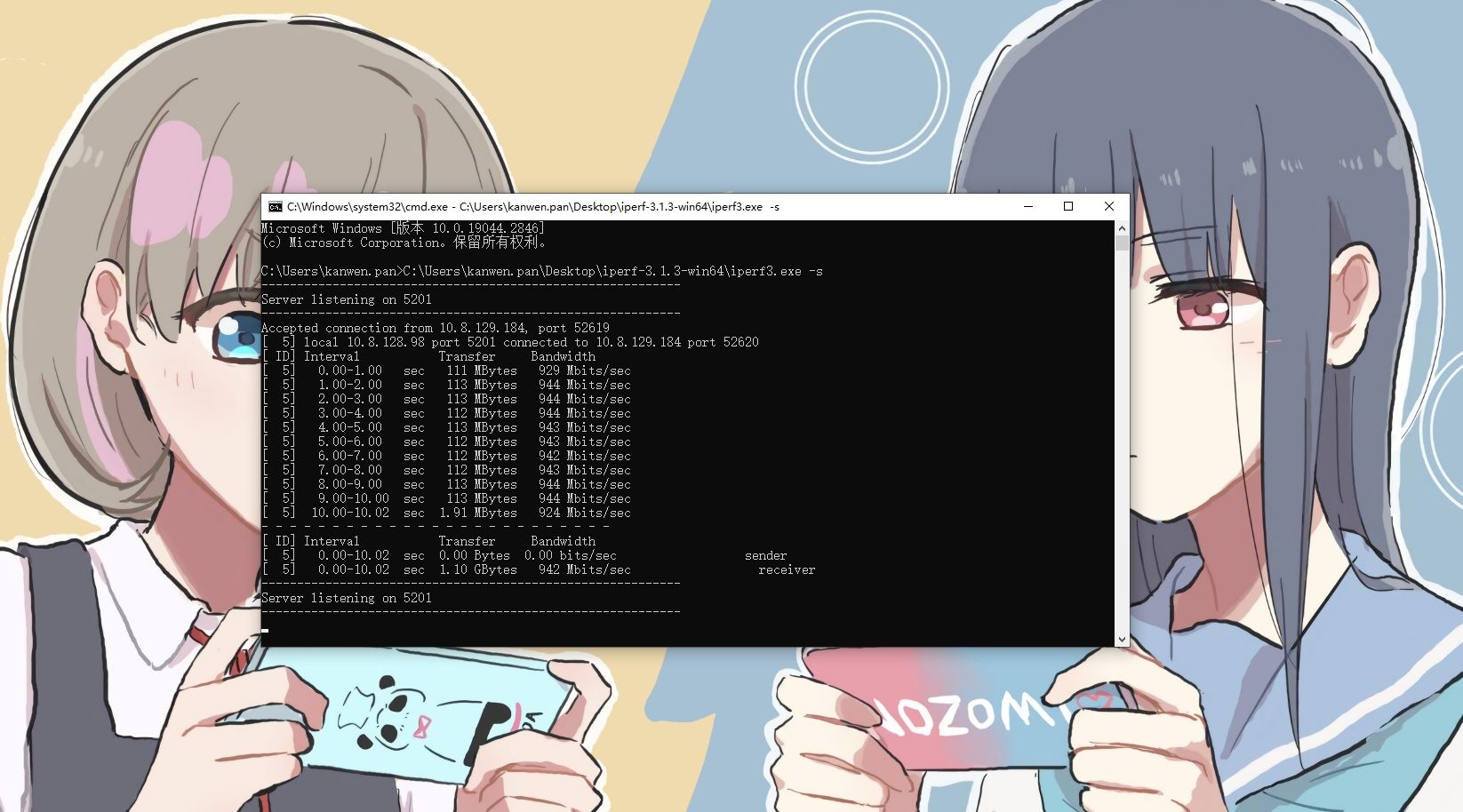
(it is best to add a heatsink, otherwise the chip will reach 75 degrees Celsius+ without a heatsink).
6. Price
Ethernet chip: 15 RMB on Taobao, network port: a little over 2 RMB each (Taobao knock-off version).
YT9215S_Datasheet_draft_V0.1.pdf
Yutai Microelectronics Product Selection 20230308.pdf
PDF_Five-Port Gigabit Switch Based on YT9215S by Yutai Microelectronics.zip
Altium 5-port gigabit switch based on Yutaiwei YT9215S.zip
PADS_5-Port Gigabit Switch Based on YT9215S from Yutai Microelectronics.zip
BOM_Five-Port Gigabit Switch Based on YT9215S by Yutai Microelectronics.xlsx
97431
Curtain control based on the [LCSC-Liangshanpai Development Board]
The curtains can be controlled by voice and infrared. Using the Liangshanpai development board, along with rain and light sensors to collect weather information, the curtains are controlled by a motor to open and close. The motor is controlled by voice using the HLK-V20 module.
I. Raindrop Detection Principle
The common working principle of raindrop sensors is to determine whether it is raining by detecting the conductivity of water droplets. It utilizes the change in conductivity between two electrodes to measure the presence of water droplets. There is an air gap between these two electrodes, which is normally an open circuit. When a water droplet comes into contact with the electrodes, the conductivity of the water droplet causes current to flow through it, forming a current loop, thereby changing the resistance between the electrodes. By measuring the change in resistance, the presence of water droplets can be determined. ![XVuY7qQLH9rRITbVLPnt6QlfSmZgNOrCZTcEaCff.png]

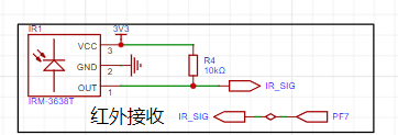
II. Infrared Remote Control Function
Infrared remote control is used for mode control using the NEC protocol. A complete NEC protocol transmission includes: a preamble, an 8-bit address code, an 8-bit address inverse code, an 8-bit command code, and an 8-bit command inverse code. Here we mainly explain how to receive the NEC protocol content sent by the infrared transmitter.
Preamble: Consists of a 9ms low level followed by a 4.5ms high level.
The 4-byte data consists of: address code + address inverse code + command code + command inverse code. The inverse code is used to verify whether the data transmission was correct and whether there was any packet loss.
Important: When transmitting data bits using the NEC protocol, the distinction between 0 and 1 is based on the duration of the received high and low levels. This is crucial for decoding.
Data transmission 0: 0.56ms low level + 0.56ms high level.
Data transmission 1: 0.56ms low level + 1.68ms high level.
Therefore, the complete time representation of receiving a data bit is as follows:
Data bit 0: 0.56ms low level + 0.56ms high level;
Data bit 1: 0.56ms low level + 1.68ms high level.
Important: When transmitting data bits using the NEC protocol, the distinction between 0 and 1 is based on the duration of the received high and low levels. This is crucial for decoding.
Data transmission code 0: 0.56ms low level + 0.56ms high level;
Data transmission code 1: 0.56ms low level + 1.68ms high level;
Therefore, the complete time representation of receiving a data bit is as follows:
Data bit 0 received: 0.56ms low level + 0.56ms high level;
Data bit 1 received: 0.56ms low level + 1.68ms high level;
There is also a repeat code, which consists of a 9ms low level and a 2.5ms high level. When an infrared signal is continuously transmitted, it can be transmitted quickly by sending repeat codes.
The tick here should be changed to a 1µs timer!
![Screenshot 2023-10-16 214212.png]
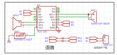
III. The
HLK-V20 voice control module is a high-performance, purely offline voice recognition module launched by Hailink Electronics for numerous purely offline control scenarios and products. It can be widely and quickly applied to smart homes, various smart small appliances, 86-type set-top boxes, toys, lighting fixtures, industrial applications, medical devices, IoT devices, automobiles, security and lighting, and other products requiring voice control. The HLK-V20 supports offline recognition of 150 local commands, and allows for free customization of wake-up words, command words, and response broadcast words. It also has rich peripheral interfaces. Offline voice recognition refers to the ability to recognize only fixed command words and does not require a network connection.
This case study comes from the HLK-V20 voice recognition module in section 4.13 of the module porting manual. Following the configuration process of the reference case, the voice module pin settings in this case also select B2P3 as the serial port!![Screenshot 2023-10-16 214154.png]
IV. Program Description
1. ADC Acquisition
The raindrop sensor and photosensitive sensor here use an ADC to acquire changes in sensor voltage to determine the sensor status.
![1698285787255.png]
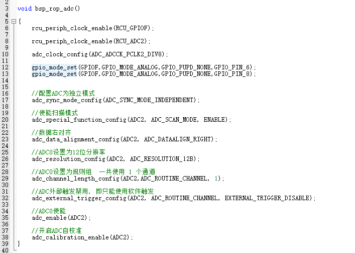
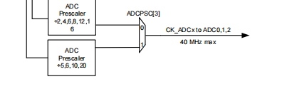
The configuration of any peripheral should first configure the clock, then the working mode, etc. The clock of GD32F470 can be configured to 200M, and the maximum clock of ADC is 40M. Care needs to be taken when dividing the frequency.
![1698286129129.png]
2. Serial Port The serial
port configuration is for two reasons: to interact with the voice module and to facilitate debugging. This serial port uses DMA mode. Of course, interrupts can also be used without them. When using interrupts, care should be taken not to print data in the timer in the motor driver, as two interrupts will have an impact, causing the motor to run slowly and not stop.
![1698286302793.png]

3.
Infrared transmission time is very short, so the tick is configured to 1µs, and the high and low level times of the infrared signal are obtained to determine whether the infrared transmission is normal.
![1698286804891.png]

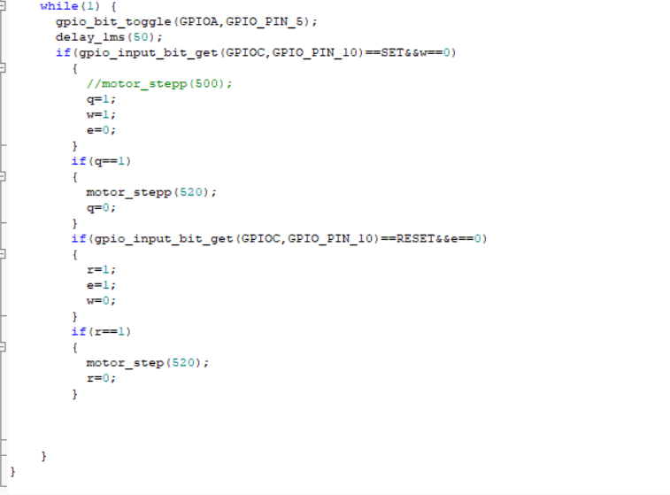
4. Motor drive:
The rotation of the motor is controlled by the high and low levels at different positions. Here, an array and a for loop are used to control the number of loops to make the motor rotate. A timer is used here to make the motor rotate at a regular high speed.
![1698287126209.png]

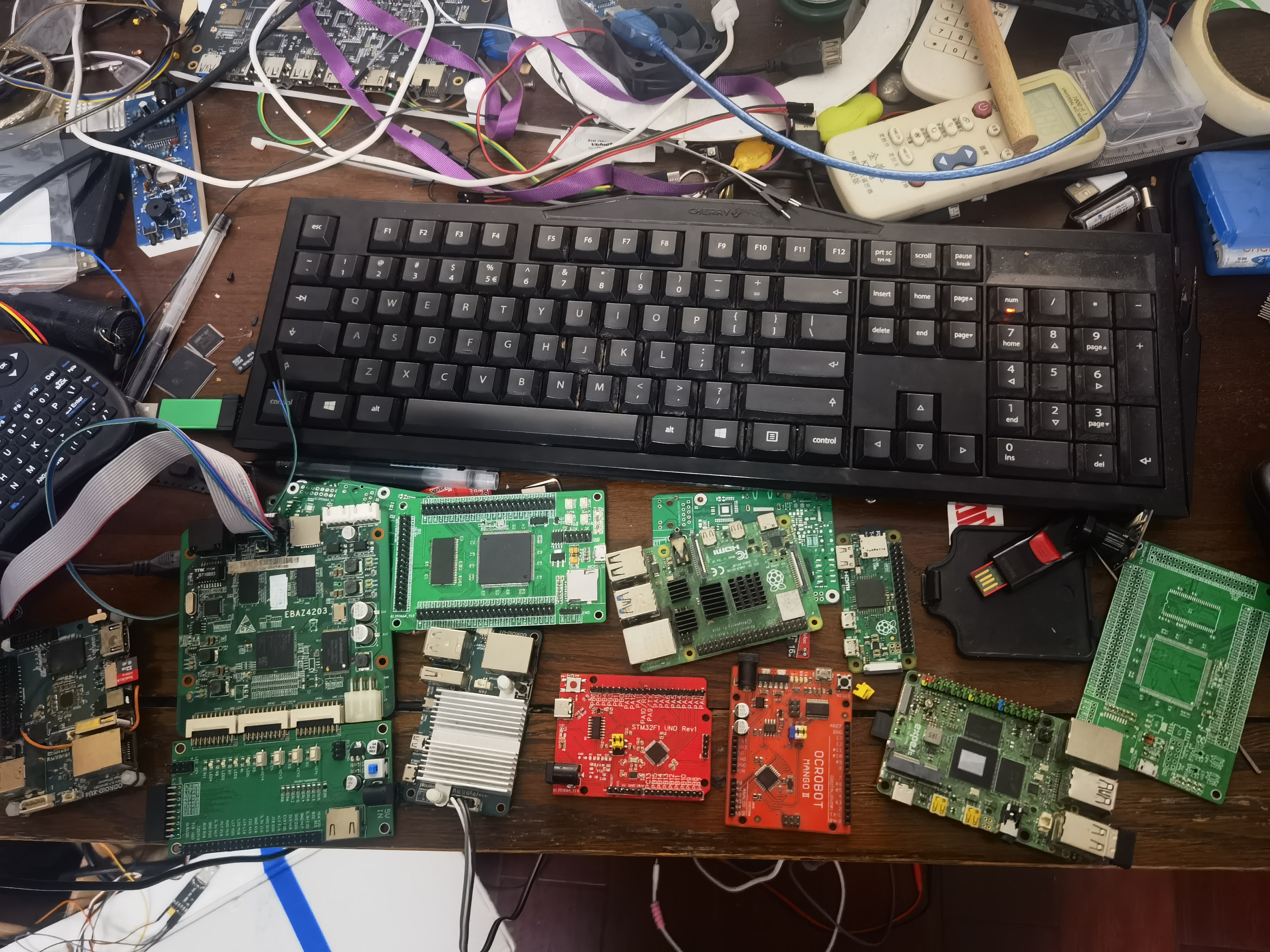
V. Physical demonstration
![a2a6fd735995d03f14fa00e4cbdf847.jpg]

Video: ![Uploading_daf7b76e-78d4-46da-b28c-be83f741b5a7]()
video.mp4
GD32F470 template.zip
PDF_Based on [LCSC-Liangshanpai Development Board] Curtain Control.zip
Altium-based curtain control software (based on the LCSC-Liangshanpai development board).zip
PADS_Curtain Control Based on [LCSC-Liangshanpai Development Board].zip
BOM_Based on [LCSC-Liangshanpai Development Board] Curtain Control.xlsx
97432
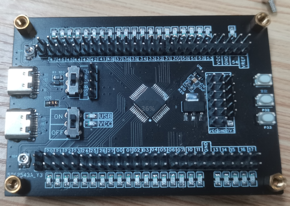
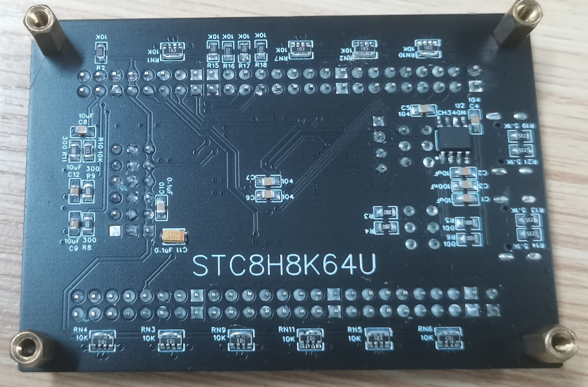
STC8H8K64U core board
Verification of STC8H8K64U Function Board
This document describes
the design of a minimum system board for the STC8H8K64U. Each I/O pin has an LED for easier pin status monitoring. It utilizes dual Type-C ports for serial or USB download functionality.
Features of the chip
include: ● Wide operating voltage range: 1.9~5.5V
● 60 I/O pins
● Common functions such as IIC, SPI, and UART
● Even the most expensive model (LQFP64) costs only 2.5 RMB.
The following is the internal block diagram

and schematic of the STC8H8K. The design is
based on the STC8H datasheet, with all pins brought out for easy external function verification.

A physical demonstration is also provided.
STC8H-20231018.pdf
Demo video.mp4
PDF_STC8H8K64U core board.zip
Altium_STC8H8K64U core board.zip
PADS_STC8H8K64U core board.zip
BOM_STC8H8K64U Core Board.xlsx
97434
NFC Card 2
This is a color-screened NFC card.
This is a beautiful NFC card design.

PDF_nfc card2.zip
Altium_nfc card2.zip
PADS_nfc card 2.zip
BOM_nfc card 2.xlsx
97435
The Mini Radio based on the RDA5807 is compact and has a long battery life.
This mini radio, designed based on the RDA5807 integrated chip, measures only 36*36*15mm. A full charge provides up to 20 hours of continuous use. It uses an earphone cable as an antenna and can also be connected to an external M3 threaded telescopic antenna. It is inexpensive and easy to solder.
1. Project Introduction:
Project Name: Mini Radio;
Station Search Method: Automatic;
Supported Frequency: 50-108 MHz;
Demodulation Method: FM;
Dimensions: 36*36*15mm;
Battery Life: Approximately 20 hours of continuous listening using 220mAh*2 batteries; Finished
Product Weight: Approximately 18g.
Employs RDA5807 integrated chip for simple circuitry; built-in headphone driver for high reliability.
The step-down LDO section uses RT9013-30GB for high conversion efficiency and stability.
The charging section uses TC4056 for affordability and fast charging.
2. Update Directory:
2023.08.05: Created this project
2023.08.07: Completed project design
2023.08.15: Project feasibility verified
2023.08.19: Tested battery life of 20 hours
2023.08.30: Added four more units and started aging tests
2023.09.30 : Tested continuously for 30 days, with very stable results.
2023.10.25 : Established an open-source project and uploaded and produced subsequent files.
3: Documentation:
The BOM is in the attachment; the first column contains detailed tips for selecting less common materials.
BOM_RDA5807_V3.0.1_Single Board_RDA5807_V3.0.1_Single Board_2023-10-25.xlsx
PDF_Mini Radio Based on RDA5807: Compact Size and Long Battery Life.zip
Altium Mini Radio based on RDA5807: Compact Size, Long Battery Life.zip
PADS_Mini Radio Based on RDA5807: Compact Size, Long Battery Life.zip
BOM_Mini Radio Based on RDA5807: Compact Size and Long Battery Life.xlsx
97436
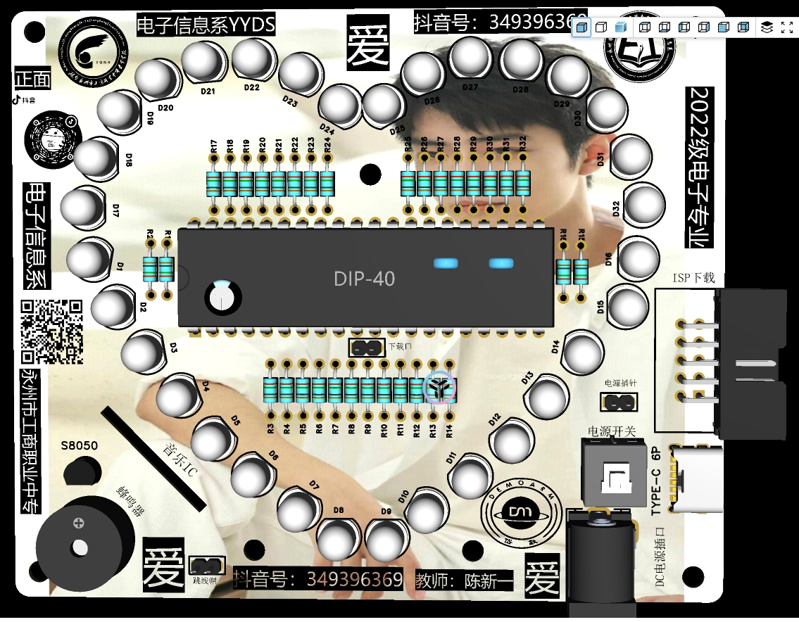
Microcontroller Heart Circuit
This microcontroller-based heart-shaped circuit features excellent heart-shaped positioning and integrates music playback and ISP download functions. It supports AT microcontrollers and is an excellent project for beginners or students to practice with!
This project is a circuit based on a 51 microcontroller that controls 32 LED heart shapes. The hearts are aesthetically pleasing, offer a variety of effects, and integrate music playback and ISP download functions to support AT microcontrollers. It is an excellent project for beginners or students to practice!
66.mp4
PDF_Microcontroller Heart Circuit.zip
Altium_Microcontroller Heart Circuit.zip
PADS_Microcontroller Heart Circuit.zip
BOM_Microcontroller Heart Circuit.xlsx
97437
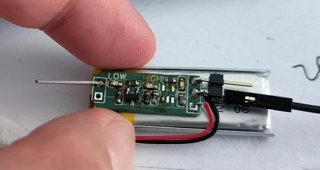
Logic level test pen
This invention addresses the difficulty of using a multimeter to test high and low voltage levels, and provides a visual representation of these levels.
When debugging the serial port, a multimeter simply couldn't detect voltage changes of more than a few bytes, so a level tester was made.
This solves the problem of multimeters not easily measuring high and low levels, providing a visual display of these levels. The image below is of the older version; the newer version hasn't been prototyped yet.
Advantages of this solution:
1. No switch required, ready to use.
2. Simple circuit, suitable for DIY .
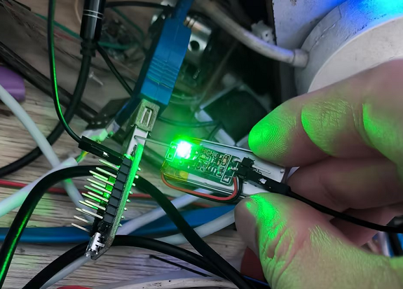
3. Convenient charging; simply plug it into the USB port of the charger (USB charging added in version 1.1).
Measures high and
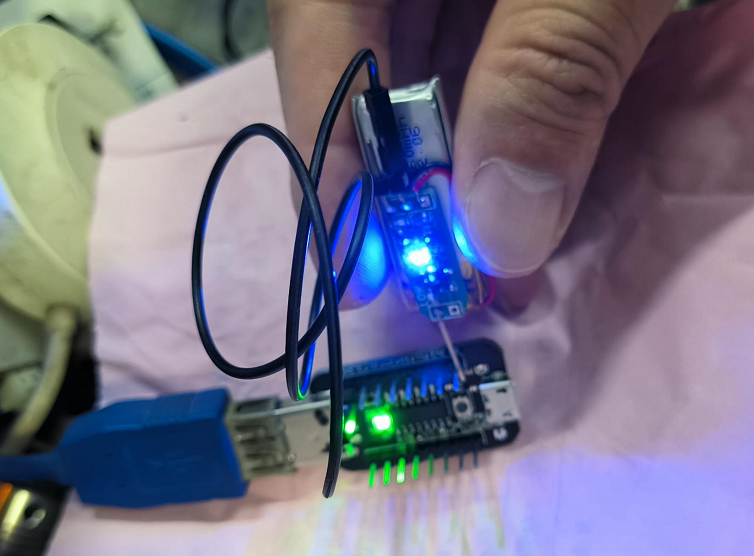
low levels.
BOM_Logic Level Tester.xlsx
97438
Smart curtain control
The intelligent curtain control system, based on the Liangshan School of painting, uses a voice module to drive a motor via commands to open and close the curtains.
"Little Wang—Open the curtains!" The motor rotates forward, and the curtains are opened.
"Little Wang—Close the curtains!" The motor rotates backward, and the curtains are closed.
This is the voice command for controlling the curtains, using the HLK-V20 voice recognition module. The main controller is Liangshanpai; other components can be purchased from LCSC. The motor is a 28BYJ-48 stepper motor I found (I couldn't afford the recommended motor; I only had a 50 RMB coupon, and LCSC didn't sell it yet—I'm a freeloader, lol). I redesigned the PCB to be the same size as Liangshanpai for a better look. Since the microphone, speaker, and motor will definitely require wiring, I only left one interface.
I only implemented voice control; other functions have hardware components, but I didn't write the program. First, I don't know how to program; second, voice control is already quite intelligent. ![Curtain.png]
bb45d04e54210064f4c4b764e81ca6d1.mp4
Curtains.zip
PDF_Smart Curtain Control.zip
Altium Smart Curtain Control.zip
PADS_Smart Curtain Control.zip
BOM_Smart Curtain Control.xlsx
97440
electronic


 京公网安备 11010802033920号

 IRL2203N


