Project Overview:
This is a sound input device (microphone) with a built-in power supply. It uses an operational amplifier to amplify the input of a dynamic sound sensor to generate the output. In terms of human voice reception, this microphone amplifier has significant advantages over traditional circuits (external power supply, transistor amplification). The battery voltage is very stable, with no ripple (converting to high accuracy), and no additional shielding or EMI is required during use.
Product Features:
1. Simple circuit
design. Single operational amplifier design on the PCB avoids noise introduction, resulting in low noise floor, high output SNR, and anti-feedback.
Ultra-compact size; the second-generation PCB can be directly inserted into the bottom of a condenser microphone sensor, facilitating the addition of other functions.
2. Wide input voltage
allows for easy modification to various lithium batteries, sodium-ion batteries, and dry cell batteries.
Supports direct drive of a single 18650/21700 cell, allowing for operation from full charge to full discharge without impact.
Supports USB power input, allowing modification into a USB sound card.
3. Easy to modify various outputs:
Default 3.5mm output supports most sound cards.
Can be directly modified to XLR output.
Microphone cables can be modified or adapted.
A USB microphone can be created by adding a CODEC.
Can be connected to a sampling DAC to collect vibration signals.
4. Superb compatibility:
The shape is compatible with most microphone molds, and simple modifications can save broken microphones.
Supports single-sided panel production, facilitating mass production and reducing costs.
Built-in 20~20kHz filter, compatible with most dynamic microphones/microphone cores on the market.
5. Superb temperature stability :
Normally operates from -40~80℃*, unaffected by extreme cold or heat.
Operating temperature: -40~+120℃, suitable for industrial applications (minor component modifications required), ideal for scientific research, and for instruments detecting small vibrations (paired with a vibration horn to collect vibrations).
*When the ambient temperature is >40℃, please use an external power supply. It is recommended to connect an appropriately sized capacitor in parallel at the power input. To better reproduce the input signal over a wide temperature range, it is recommended to use low-temperature drift resistors (below 100ppm) for R3 and R6. The

dynamic
microphone converts sound signals into voltage signals. Sensitivity is the indicator of this conversion performance. The converted voltage is usually very small, so an amplifier is needed. For most applications requiring amplification of small audio signals, a bandpass filter + operational amplifier circuit is sufficient to perform all functions well. The circuit shown below illustrates this basic amplification function: (Signal level amplification factor k = R11/R10 = 10, converted to audio decibels: Gain = 20 * lg(k) = 20dB).
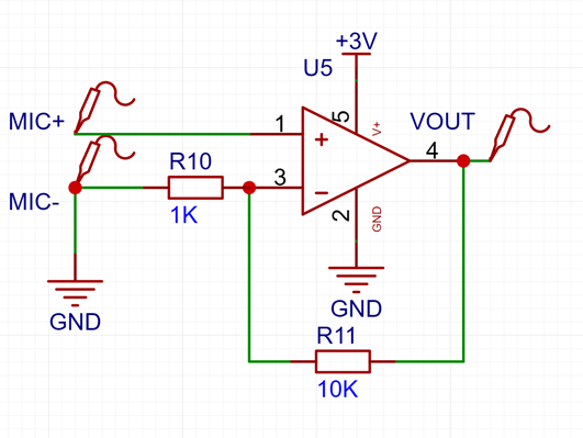
This circuit achieves accurate voltage amplification through negative feedback, but it has some drawbacks that need improvement:
1. This circuit lacks any filtering, which may amplify high-frequency noise and cause self-oscillation.
2. This circuit may experience a situation where the MIC+ potential is lower than the GND potential, at which point VOUT can only output 0V, resulting in waveform loss.
3. The MIC+ potential is not near the op-amp's optimal operating range - (1/2 * VCC), which introduces distortion due to common-mode voltage*.
*Here, common-mode voltage refers to (1/2 * VCC – “'MIC-' voltage”).
Based on the above problem, the following is required:
1. Add a bandpass filter
. 2. Introduce a 1/2 VCC point or negative voltage power supply.
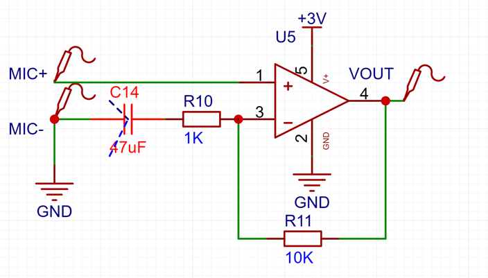
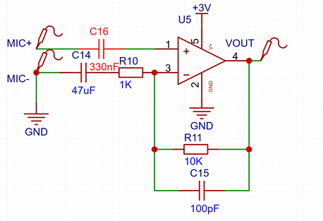
For requirement 1, high-pass and low-pass filters need to be added, retaining only the 20~20kHz signal.
First, add a high-pass filter capacitor, directly connected in series in the input circuit;
add a low-pass filter capacitor, connected in parallel with the feedback resistor.

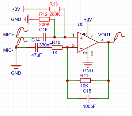
For requirement 2, first add a coupling capacitor between MIC+ and the op-amp input comparison positive terminal;
then add a voltage divider circuit composed of resistors of appropriate size to maintain the op-amp input voltage at around 1/2 * VCC, thus recording the full-wave signal.
If the output is not directly connected to the ADC, considering that most receiving devices need to isolate the DC component, an output capacitor is added to isolate DC. Note that the capacitor here should not be too small (it should be large enough to ensure the transmission of human voice; it can be customized according to requirements).

For component selection
, the relatively affordable TLV2471 is chosen, using a single-ended input/output method to amplify the signal. For those seeking the lowest possible cost, the LMV321 can be used directly instead of the TLV2471. Other components remain unchanged; the finished circuit performance is almost identical, except for a slight decrease in SNR. The
resistors used here are ordinary temperature drift (500ppm/℃) 1% precision resistors, suitable for most indoor applications. If a higher temperature range is required, please follow the product's specifications. The PCB layout and routing are compact, effectively reducing interference from external noise. Therefore, under normal circumstances, there is no need for additional shielding on the PCB. However, to ensure compatibility with single-sided PCB layouts, no additional vias are added to the top layer of the PCB as return paths. If using a double-layer PCB, It is recommended to remove the top-level GND copper pour. Add several grounding vias next to the GND pin of each component before connecting to the GND network to minimize the adverse effects of backflow. Output Design and Acquisition: 1. The 3.5mm output circuit is a single-ended balanced output. The simplest solution is to connect a 3.5mm headphone cable to the sound acquisition device. In this case, simply use a male-to-male 3.5mm headphone cable to connect the amplifier board and peripherals. 2. The XLR balanced output circuit can be configured for XLR balanced output. This requires soldering balanced cables. Before soldering, the corresponding wire definitions need to be found. To reduce noise, the following points should be noted: 1. When using XLR output, do not turn on the +48V phantom power of the recording device. 2. Connect the XLR cold (cold end, signal-) to the PCB "GND", and the hot (hot end, signal-+) to the PCB signal output terminal. If the microphone has a metal casing, it is recommended to connect the "shield" (casing) to the casing; otherwise, do not connect the shield. Failure to follow the above method will result in 50Hz interference. 3. When using XLR, 1. Ensure the receiving device casing has proper grounding, especially if the microphone has a metal casing, as leakage could have serious consequences. 2. For TS (two-pin recording plug) and RCA (lotus plug) (non-differential wiring) , only connect the shield to the PCB "GND", connect the signal to the PCB signal output, and do not make any connections to the microphone casing. 3. Fiber optic, radio, or other signal modulation integration requires corresponding modulators and demodulators. A USB ADC chip can be integrated into the microphone to create a USB microphone, or an SPDIF decoder and coaxial interface or audio fiber optic cable can be integrated to create a digital audio microphone. Note that these additional functions may significantly increase power consumption.


 京公网安备 11010802033920号

 5082-511G-L0000


