This project is prohibited from commercial use without authorization
. Authorized sales are available through Taobao-ABrobot Smart and Taobao-Tacker Innovation.
Two open-source wireless debuggers have been released, which you can choose based on cost and usage environment:
CH32 version: Cost approximately 100 RMB, under test conditions, 98KB/s wired download speed, 48KB/s wireless download speed, strong anti-WiFi interference capability, compatible with lower Keil versions :
https://oshwhub.com/ylj2000/dap_hs_wl_v0-4
ESP32 version: Cost approximately 30-40 RMB, under test conditions, 94KB/s wired download speed, 43KB/s wireless download speed, moderate anti-WiFi interference capability; poor WiFi environment may cause download speed reduction or even download failure, but it has little impact on normal personal use, only a greater impact in environments such as competition venues, Keil version higher than 5.29 is required.
https://oshwhub.com/ylj2000/dap_hs_esp_open
Update Log
#2023.09.13
Updated module version and corresponding shell
#2023.09.01
Initial Release
I. Introduction
Usage Environment: MDK>=5.29, IAR>=8.32. The main chip only requires two ESP32-S3FN8 or ESP32-S3FH4R2 chips, with a BOM cost of around 30 RMB. Ready-made modules can also be used. Wireless performance is approximately twice that of common wired FS+HID DAPs, and even close to wired STLink V2. The distance can reach over 30m (further distances have not been tested, but there is no significant speed attenuation).
A wireless debugger consists of a transmitter (Host) and a receiver (Slave). The hardware and software at both ends are completely identical. Pairing, mode switching, and wireless channel adjustment can be performed via buttons. Like regular DAPs, it supports debugging ARM microcontrollers (such as STM32, GD32, etc.), supports SWD and JTAG, hardware and software resets, and virtual serial ports. After pairing, it's plug-and-play, requiring no driver installation (WIN10 and above); it doesn't use WiFi, but rather a 2.4G-like wireless connection, so there's no need to wait for a wireless connection. Besides wireless mode, it can also be switched to wired mode (USB) for use in complex wireless environments, where performance is better. Different indicator light colors represent different modes: red for wired mode (USB), blue for wireless transmitter (Host), and green for wireless receiver (Slave).
II. Development Background
Currently, commonly used debuggers for ARM microcontrollers include ST-Link, J-Link, and DAPLink. Although their functions and speeds differ, almost all of them can only be used with a USB cable. This can easily damage the computer or even injure the user in some potentially dangerous debugging tasks, such as with robots or power supplies. Wireless debuggers can effectively avoid these situations and greatly optimize the debugging experience, eliminating the need to carry a computer and USB cable around with the target.
Most wireless debuggers on the market, like DAPLink, are based on the CMSIS-DAP protocol. However, their performance and price vary greatly. Many offer extremely low costs and poor performance at exorbitant prices, making them very difficult to use and causing many developers, including myself, to make mistakes. I've tried many wireless debuggers, and the only one that was relatively good was the one from Zhengdian Atom, but its price was too high (300+ RMB), making it unaffordable. Therefore, I decided to DIY a good and inexpensive wireless debugger. In my previous open-source project, I developed one based on CH32V307+SX1281, costing less than 100 RMB, but with performance comparable to Zhengdian Atom. However, the cost was still relatively high, so I planned to develop a cheaper wireless debugger that still met general usage requirements.
The performance of the previous version was approximately: MDK+STM32F4, program speed 98KB/s wired, 48KB/s wireless. The initial target speed for this version was: wired speeds close to the previous version, and wireless speeds around 30KB/s. To achieve this, HID mode DAP was not feasible, so a WinUSB-based Bulk mode was necessary. For cost reasons, choosing a microcontroller with built-in USB and wireless capabilities was essential. Initially, the ESP32-S2 and ESP32-S3 were considered, but in subsequent tests, the ESP32-S2's TinyUSB consumed too much CPU resources, resulting in wired speeds only reaching 40+ KB/s; while the ESP32-S3, being a dual-core design, achieved wired speeds exceeding 90KB/s after task allocation to both cores. Therefore, despite the higher price of the S3, the ESP32-S3 was chosen.
After hardware design and software optimization, the final performance even exceeded the initial design goals, reaching speeds very close to the previous version's 100-yuan configuration, while the cost of this version was only about 30 yuan. Program speeds were 95KB/s wired and a maximum of around 45KB/s wirelessly. Of course, since ESP uses a WiFi channel, the actual speed may decrease depending on the wireless environment, but it is generally around 40KB/s. This performance is very close to that of the Zhengdian Atom wireless debugger. At one-tenth the price, what more could you ask for?
III. Finished Product Showcase

III. Manufacturing Process
1. PCB Fabrication: Fabricate the PCB according to the open-source documentation, selecting a 1.0mm board thickness.
2. PCB Soldering: Most of the components used can be purchased from LCSC, or you can find cheaper options on Taobao. The attached BOM contains reference purchase links; it is recommended to choose according to your needs.
3. Firmware Download: After confirming the PCBA fabrication is correct, download the debugger firmware. Press and hold button A while connecting the debugger to the computer via USB cable. Open the flash_download_tool in the attachment and select the following configuration. After entering the interface, select firmware, set the starting address to 0, and select the corresponding serial port. It is recommended to first click ERASE to erase the Flash, and then click START to burn. After burning, power on again; the default mode is USB (indicator light is red).

4. Pairing: For the first module, press and hold button B to power on until the indicator light turns purple, then release. The second module is powered on by pressing and holding button B. After the indicator light turns purple, the two modules will instantly transform into master (blue) and slave (green) respectively. At this point, the communication parameters and modes at both ends are automatically set. These can be changed using the buttons if needed. The master and slave modules need to be powered on again after completion.
5. Button Function Setting Mode: Press and hold button A until the indicator light turns yellow. Short press button B to adjust to the desired mode based on the indicator light color. If you need to save the configuration to Flash, i.e., retain the current configuration upon next power-on, press and hold button A until the indicator light flashes yellow, then short press button A to exit. If it's only for temporary use and you don't need to save the configuration to Flash, simply short press button A to exit. Setting the Wireless Channel: Press and hold button B until the indicator light flashes. The flashing color and number of flashes indicate the current WiFi channel: green for channels 1-5, red for channels 6-10, and blue for channels 11-13. Short press button B to select the target channel, then press and hold button A until the indicator light flashes yellow, then short press button A to exit. The master and slave devices need to be configured to the same channel to communicate. After completion, both the master and slave devices need to be powered on again.
6. Testing: Test whether the download, virtual serial port, and other functions are normal.
IV. Daily Use
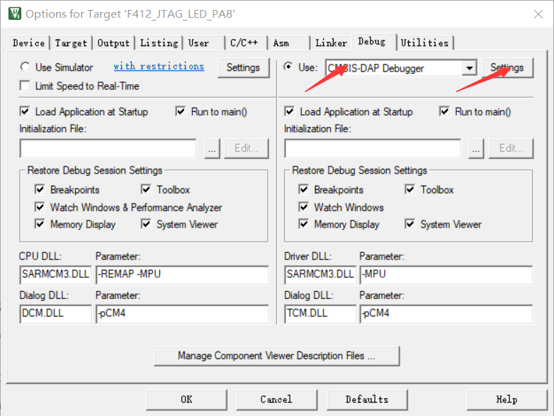
1. Keil Settings
If you encounter connection failures or unstable connections, you can try lowering the clock frequency and replacing the DuPont wires. In addition, some chip models may not be able to be debugged properly at high clock frequencies (the HK32F030MF4P6 I used is an example).

2. Interference:
If you encounter severe signal interference on the current wireless channel, try changing to a different communication channel. Excessive interference can lead to reduced speed and unstable downloads.
V. Performance Testing
Environment: Keil MDK 5.34
Target Chip: STM32F407VGT6
Firmware Size: Approximately 1024K
Testing Method: Timed with a stopwatch on a mobile phone, averaging three tests.
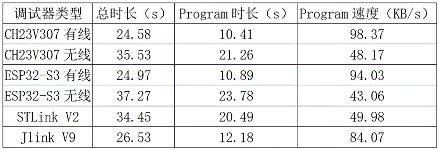
Since the Erase and Verify times are roughly the same for each downloader, the Program duration and speed, which reflect the downloader's download speed, are calculated.
In the table, CH32V307 is the previous version, and ESP32-S3 is this version. As you can see, this version of the debugger's performance is very close to the previous version. The wired mode speed slightly exceeds Jlink V9, while the wireless mode speed is slightly lower than STLink V2. I've also tested some wireless debuggers on Taobao, many of which have speeds of only a few tens of KB/s, which is normal, as the speed of a typical wired DAP is only 20+ KB/s.
For more information, please join QQ group: 770979540 for discussion.


 京公网安备 11010802033920号

 1812FS-224JSB


